Voltronic Power +Power 30U-90 User manual

Modular Online UPS
Uninterruptible Power Supply System
Version: 1.2
User Manual

Table Of Contents
1. Safety ...............................................................................................................................1
1.1 Important Safety Instructions.....................................................................................1
1.2 EMC..........................................................................................................................1
1.3 Installation information ..............................................................................................1
1.4 Maintenance .............................................................................................................2
1.5 Recycling the used battery .........................................................................................2
2 Operation & structure..........................................................................................................3
3. Installation ....................................................................................................................4
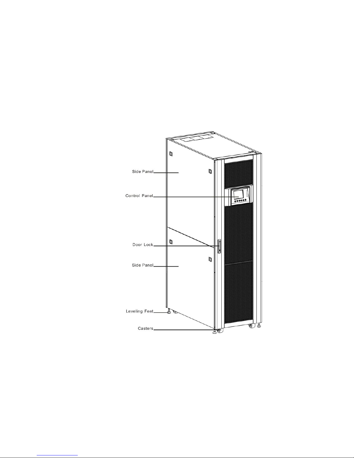
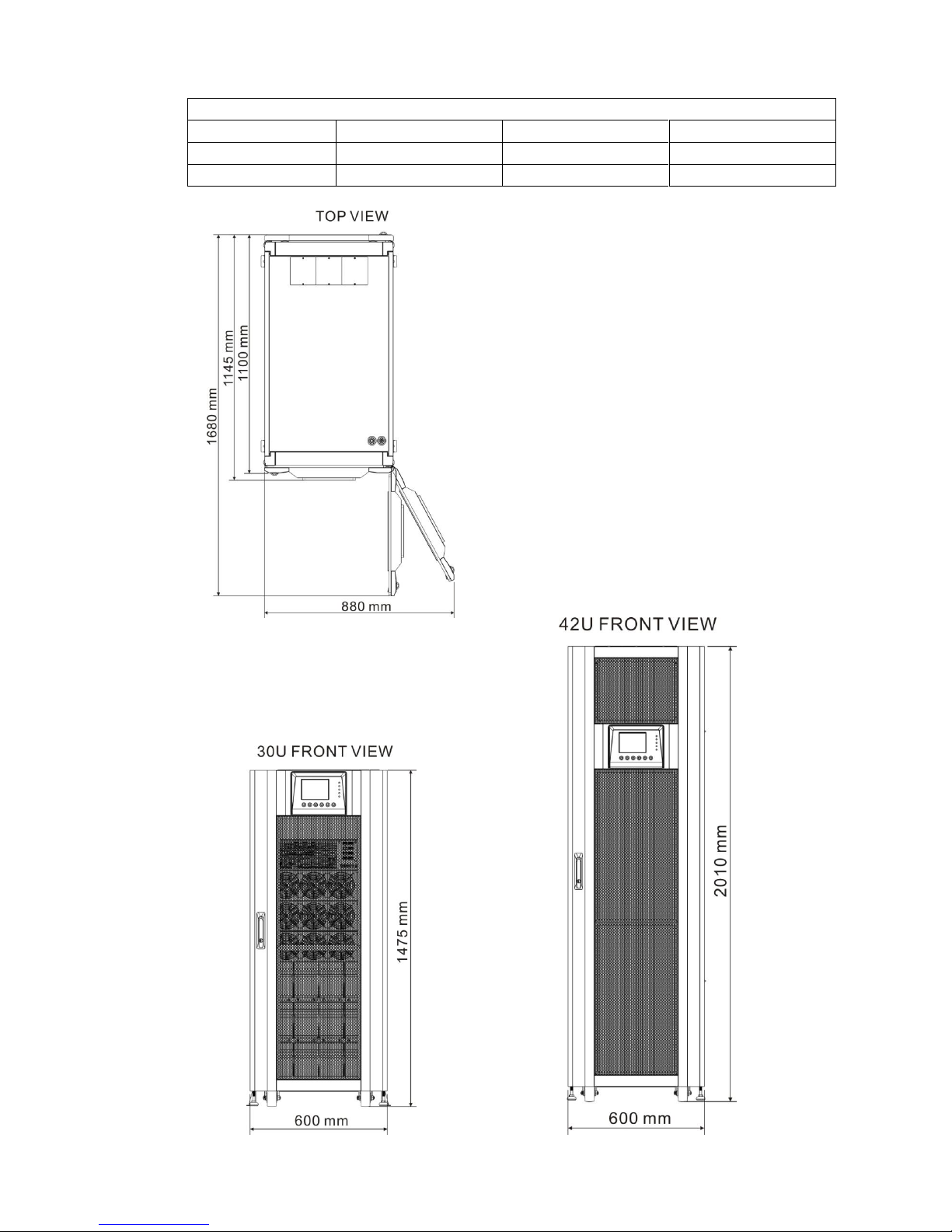
3.1 Mechanism and Exterior.........................................................................................4
3.1.1 Mechanical Data ............................................................................................5
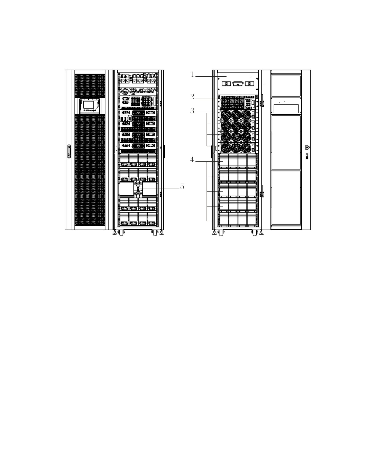
3.1.2 Other Views ..................................................................................................6
3.2 Internal Mechanisms............................................................................................8
3.2.1 Input and Output Breakers.............................................................................8
3.2.2 Wiring Terminal Block ....................................................................................9
3.2.3 Modules ...................................................................................................... 10
3.3 Control Panel & interface.................................................................................... 11
3.3.1 LED indications............................................................................................ 11
3.3.2 LCD Display................................................................................................. 11
3.3.3 Function Keys.............................................................................................. 12
3.4 Installation and Wiring......................................................................................... 12
3.4.1 Before Installation ....................................................................................... 12
3.4.2 Installation Environment .............................................................................. 12
3.4.3 Transportation ............................................................................................. 13
3.4.4 Unpacking ................................................................................................... 14
3.4.5 Positioning .................................................................................................. 15
3.5 Modules ............................................................................................................ 15
3.5.1 Power Module.............................................................................................. 15
3.5.2 Install a Power Module................................................................................. 16
3.5.3 Remove a Power Module .............................................................................. 17
3.5.4 STS Module ................................................................................................. 17
3.5.5 Remove the STS Module .............................................................................. 18
3.5.6 Install Battery.............................................................................................. 18
3.6 Power Cable ...................................................................................................... 19
3.6.1 AC input and output maximum current and power cable configuration............ 20
3.6.2 DC input maximum current and power cable configuration............................. 20
4. Control Panel and Display Description ............................................................................... 21
4.1 Introduction ............................................................................................................ 21
4.2 Screen Description................................................................................................... 23
4.2.1 Start Screen .................................................................................................. 23
4.2.2 Main Screen................................................................................................... 23
4.2.3 Menu Screen ................................................................................................. 24
4.2.4 Control Screen ............................................................................................... 24
4.2.5 Measurement Screen...................................................................................... 25
4.2.6 Setup Screen ................................................................................................. 27

4.2.7 Information Screen ........................................................................................ 37
4.2.8 Events Screen................................................................................................ 38
4.3 Alarm List ............................................................................................................... 41
5. Interface and Communication ........................................................................................... 44
5.1 Remote EPO Input Port............................................................................................ 44
5.2 BCB Port ................................................................................................................. 45
5.3 Maintenance Bypass Switch State Port ...................................................................... 45
5.4 Internal Output Switch State Port ............................................................................. 46
5.5 Battery Cabinet Temperature Detection Port.............................................................. 46
5.6 Bypass back feed Control Port .................................................................................. 47
5.7 Battery breaker Control Port..................................................................................... 47
5.8 Other Communication Interface................................................................................ 48
6. Service ......................................................................................................................... 49
6.1
Replacement Procedures Of Power Module, STS & Control Module And Battery Module 49
6.1.1 Notes ........................................................................................................ 49
6.1.2 Power Module Replacement Procedures....................................................... 49
6.1.3 STS & Control Module Service Procedures.................................................... 50
6.1.4 Battery Module replacement Procedures ...................................................... 50
6.2Replacement Procedures Of Air Filter......................................................................... 51
7. Specifications................................................................................................................ 52
7.1 Conformity And Standards ........................................................................................ 52
7.2 Environmental Characteristics ................................................................................... 52
7.3 Mechanical Characteristics ........................................................................................ 53
7.4 Electrical Characteristics (Input Rectifier) ................................................................ 53
7.5 Electrical Characteristics (Intermediate DC Circuit) ..................................................... 54
7.6 Electrical Characteristics (Inverter Output)................................................................. 54
7.7 Electrical Characteristics (Bypass Mains Input) ........................................................... 55

1
1. Safety
1.1 Important Safety Instructions
This UPS contains LETHAL VOLTAGES. All repairs and service must be performed by AUTHORIZED
SERVICE PERSONNEL ONLY. There are NO USER SERVICEABLE PARTS inside the UPS.
WARNING:
The UPS designed for commercial and industrial purpose, it is forbidden to apply for any life
sustainment and support.
The UPS system contains its own energy source. The output terminals may carry live voltage
even when UPS is disconnected from an AC source.
To reduce the risk of fire or electrical shock, UPS installation has to be in a temperature and
humidity controlled, indoor environment. Ambient temperature must not exceed 40°C. The
system is not intended for outdoor use.
Ensure all power is disconnected before performing installation or service.
Service and maintenance should be performed by qualified service personnel only.
1.2 EMC
WARNING:
This is a product for commercial and industrial application in the second environment - installation
restrictions or additional measures may be needed to prevent disturbances.
1.3 Installation information
WARNING:
Installation must be performed by qualified personnel only.
The cabinets must be installed on a level floor suitable for computer or electronic equipment.
The UPS cabinet is heavy. If unloading instructions are not closely followed, cabinet may
cause serious injury.
Do not tilt the cabinets more than 10∘.
Ground conductor is properly installed.
Installation and Wiring must be performed in accordance with the local electrical laws and
regulations.
The disconnection device should break line and neutral conductors- four poles for three
phases.
Before working on this circuit
-Isolate Uninterruptible Power System (UPS)
-Then check for Hazardous Voltage between all terminals including
the protective earth.
Risk of Voltage Backfeed
The isolation device must be able to carry the UPS input current.

2
1.4 Maintenance
UPS is designed to supply power even when disconnected from the utility power. After
disconnect the utility and DC power, authorized service personnel should attempt internal
access to the UPS.
Only qualified service personnel should perform the battery installation.
Do not disconnect the batteries while the UPS is in Battery mode.
Disconnect the charging source prior to connecting or disconnecting terminals.
Batteries can present a risk of electrical shock or burn from high short circuit current.
The following PRECAUTIONS should be observed
1. Remove watches, rings, or other metal objects.
2. Use tools with insulated handles.
3. Wear rubber gloves and boots.
4. Do not lay tools or metal parts on top of batteries or battery cabinets.
5. Disconnect the charging source prior to connecting or disconnecting terminal.
6. Determine if the battery is inadvertently grounded. If it is, remove the source of the
ground. Contact with any part of a grounded battery can result in electrical shock. The
likelihood of such shock is reduced if such grounds are removed during installation and
maintenance.
When replacing batteries, use the same number of sealed, lead-acid batteries.
Do not dispose of battery in a fire. The battery may explode.
Do not open or mutilate the battery. Release electrolyte is harmful to the skin and eyes, and
may be toxic.
1.5 Recycling the used battery
Do not dispose of the battery in a fire. Battery may explode. Proper disposal of battery is
required. Refer to your local codes for disposal requirements.
Do not open or mutilate the battery. Released electrolyte is harmful to the skin and eyes. It
may be toxic.
Do not discard the UPS or the UPS batteries in the trash. This product contains sealed,
lead-acid batteries and must be disposed of properly. For more information, contact your local
recycling/reuse or hazardous waste center.
Do not discard waste electrical or electronic equipment (WEEE) in the trash. For proper
disposal, contact your local recycling/reuse or hazardous waste center.

3
2 Operation & structure
Figure 2-1: Wiring diagram for dual inputs
Figure 2-2: Wiring diagram for single input

4
3. Installation
3.1 Mechanism and Exterior
In the front of the UPS, there are control interface (LCD Panel) and door lock. Inside the cabinet,
there are an STS Module, 1~8 Power Module slots and Battery modules.
All wiring terminal blocks are allocated in the back of system. The side panels are lockable. The
casters at the bottom of the UPS cabinet can be used to move over short distances. There are four
leveling feet to fix and stabilize the UPS cabinet on the ground.
Figure 3-1:UPS Exterior

5
3.1.1 Mechanical Data
Dimensions
UPS cabinet
Width
Depth
Height
30~90Kw(30U)
600mm
1100m
1475mm
30~210Kw(42U)
600mm
1100m
2010mm
Figure 3-2: Dimensions

6
3.1.2 Other Views
‧Front View : Unlock and open the front door to see STS Module, Switch unit, Power Module and
Battery Module.
‧Rear View : Unlock and open the rear door to see Battery Breaker.
(Rear View) (Front View)
1. Switch unit
2. Bypass module
3. Power module
4. Battery module
5. Battery breaker
Figure 3-3: Front and Rear View

7
Configurations:
There are two basic configurations for different applications.
It’s required to have battery module for Standard Series.
Please consider the external battery space and wiring gauge for Extended Series.
Standard Series
Extended Series
Photo
Cabinet
Height
30U
42U
30U
30U
42U
Switch Unit
1
1
1
1
1
STS
1
1
1
1
1
Max. Power
Module
3
4
4
6
8
Battery
Module
12
20
N/A
N/A
N/A

8
3.2 Internal Mechanisms
After opening the front door, you can see the Switch unit, Bypass module, Power module and
Battery module. After opening the back door, you can see the Battery Breaker and input/ output
wiring terminal block. Please refer to the following sections.
3.2.1 Input and Output Breakers
Open front and back door. The Input Breaker, Bypass Breaker and Output Breaker are located on
the front of the UPS. The Battery Breaker and input/ output wiring terminal block are at the back of
the UPS. See Figure 3-4.
Figure 3-4: Front View/Output, Bypass, and Main Input Breakers

9
3.2.2 Wiring Terminal Block
Open the UPS’s back doors and you will see the wiring terminal block. For connection instructions,
please refer to Figure 3-5.
Item
Function
Description
Output Block
Connects the critical loads
Includes R, S, T and
Neutral terminals.
Bypass Input Block
Connects bypass AC source
Includes R, S, T and
Neutral terminals.
Main Input Block
Connects main AC source
Includes R, S, T and
Neutral terminals.
For UPS Grounding
For UPS grounding
Includes one grounding
terminal.
Battery Input Block
Connects an external battery
cabinet
Includes
Positive (+), Negative (-)
and Neutral (N) terminals.
Figure 3-5: Rear View & Wiring Terminal Block

10
3.2.3 Modules
The STS & Control module and Power Module allow quick maintenance, replacement and
expansion. The module latches secure the modules in place.
‧STS & Control Module: It includes control, power, communication circuits, an internal Static
Transfer Switch and a fuse.
‧Power Module: Each power module capacity is 30kVA/ 30kW. It includes a power factor
correction rectifier, a battery charger, an inverter and control circuits.
‧Battery Module: It contains 4 sets of 10 pieces 12V/9Ah batteries inside of one battery
compartment.
Figure 3-6: Front View with Modules
STS & control module

11
3.3 Control Panel & interface
The front access Graphic Display & Control interface brings all measured parameter, UPS & Battery
current states and Alarms. Through the interface, users can easily monitor status and configure
settings. For detailed information, please refer to the charter 4.
Figure 3-7: Control Panel
3.3.1 LED indications
LED
Color
Status
Definition
INPUT
Green
On
Input source is normal.
Flashing
Input source is abnormal.
Off
No input source
BYPASS
Green
On
Load on Bypass.
Flashing
Input source is abnormal.
Off
Bypass not operating.
INVERTER
Green
On
Load on inverters.
Off
Inverters not operating.
BATTERY
Yellow
On
Load on Battery.
Flashing
Low battery
Off
Battery converter is normal and battery is charging.
ALARM
Red
On
UPS fault.
Flashing
UPS alarm.
Off
Normal.
3.3.2 LCD Display
Graphic display and all measured parameters.

12
3.3.3 Function Keys
Control Key
Description
Esc
Return to previous screen or cursor displacement. When screen is in
Main screen, it will enter setting menu by pressing ESC key.
Up(Left)
Key for menu page navigation or digit modification.
Down(Right)
Key for menu page navigation or digit modification.
Enter
Confirmation of commands, or cursor displacement.
Home
Return to Main screen.
Power
On/Off
Turn on UPS or Turn off UPS.
3.4 Installation and Wiring
3.4.1 Before Installation
Due to different installation environments, please read this user manual thoroughly before
installation and wiring. Only authorized engineers or service personnel can perform installation and
maintenance. If you want to install the UPS by yourself, installation must be under the supervision
of authorized engineers or service personnel.
If you use a forklift or other equipment to move the UPS, please make sure its load bearing is
sufficient.
3.4.2 Installation Environment
The UPS is designed for indoor use only. Do not install or place it in an outdoor area.
Make sure that transportation routes (e.g. corridor, door gate, elevator, etc) and installation
area can accommodate and bear the weight of the UPS, the external battery cabinet and
handling equipment.
Ensure that the installation area is big enough for maintenance and ventilation.
Keep the installation area’s temperature around 30°C and humidity within 90%. The highest
operating altitude is 2000 meters above sea level.
The UPS is intended for indoor installation and should be located in an environment with clean
air and with adequate ventilation to keep the ambient temperature within the specified
operating range. The UPS is air-cooled with the aid of internal fans. Cold air enters the UPS
through.
If necessary, install a system of room extractor fans to avoid room temperature build-up. Air
filters are necessary if the UPS is operated in a dusty environment.
Note: The UPS is suitable for mounting on concrete or other non-combustible surface only.
The UPS is air-cooled with the aid of internal fans. Cold air enters the UPS through the
ventilation grilles at the front of the cabinet and hot air is released through the grilles at the
back. Do not cover the ventilation openings.
Do not allow unauthorized personnel to enter the installation area. Assign specific personnel to
keep the UPS key.

13
For safety concerns, we suggest that you shall:
1. Surroundings of the installation area with CO2 or dry powder fire extinguishers.
2. Install the UPS in an area where the walls, floors and ceilings were constructed by fireproof
materials.
It is recommended that you parallel the external battery cabinets to the UPS. The following
clearances are suggested:
1. Keep a clearance of 100cm from the top of the UPS for maintenance, wiring and ventilation.
2. Keep a clearance of 100cm from the back of the UPS and the external battery cabinets for
ventilation.
3. Keep a clearance of a 150cm from the front of the UPS and the external battery cabinets for
maintenance and ventilation.
3.4.3 Transportation
Warning
The UPS is fixed on the pallet with four balance supports. When removing them,
pay attention to the movement of the casters to avoid accidents.
The cabinet can be pushed forward or backward only. Pushing it sideward is not
allowed. When pushing the cabinet, take care
not to overturn it as the gravity center is high.
If you need to move the UPS over a long distance, please use appropriate equipment like a
forklift. Do not use the UPS casters to move the over a long distance.
After the UPS has been removed from the pallet to ground, we suggest that at least three
people move the UPS to the installation area. One person use hands to hold a lateral side of
the UPS, one person hold the other lateral side of the UPS with hands, and one person use
hands to push the UPS either from the front side or from the backside to move the unit to the
installation area and avoid tipping the UPS.
The casters are designed to move on level ground. Do not move the UPS on an uneven
surface. This might cause damage to the casters or tip the UPS which could damage the unit.
Ensure that the UPS weight is within the designated surface weight loading of any handling
equipment.
At the bottom of the UPS, there are four casters to help you to move the UPS to a designated
area. Before you move the UPS, please turn the four leveling feet counterclockwise to raise
them off the ground. This protects the leveling feet from damage when moving the UPS.
Please use sufficient manpower(at least six people) and equipment (e.g. forklift) to carefully
move the UPS from its pallet to ground. Please pay attention to the movement of the casters to
avoid accidents.
Figure 3-8: Leveling foot and caster

14
3.4.4 Unpacking
After shipping the product to the user first check the packaging to determine intact, and then
open the package, check the equipment in good condition. If damaged, please immediately
notify the carrier.
3.4.4.1 System Packaging
1. Use a forklift to move the product to installed area. Refer to Figure 3-9.
2. Please remove 5 boards in order (from 1 to 5) as shown in Figure 3-10.
Figure 3-9 Figure 3-10
3. Put a ramp in the front of the cabinet and insert small wood into groove. Then, remove two
side panels. Refer to Figure 3-11.
Figure 3-11

15
4. Remove 4 fixing cabinet plates and loosen leveling feet by rotating in counterclockwise.
Then, move the cabinet from the pallet.
5. To fix the cabinet in position, simply rotate leveling feet in clockwise.
Figure 3-12 Figure 3-13
3.4.5 Positioning
Leveling feet are provided at the bottom of the UPS cabinet to prevent the UPS from moving once
it has been placed to its final position. For optimal design life, the installed place must be:
easy connection
enough space to easily work on the UPS
sufficient air exchange to dispel heat produced by UPS
protection against atmospheric agents
protection against excessive humidity and high heat sources
protection against dust
compliance with the current fire prevention requirements
For VRLA (Valve Regulated Lead Acid) batteries the operating environment
temperature is kept between 20°C and 25°C. VRLA batteries are at maximum
efficiency in this temperature range
3.5 Modules
The hot-swappable Power Modules allow quick maintenance and expansion. A latch located on the
front of each module fixes and locks the module in its assigned slot. Each Power Module has an
LED indicator to show its operation status.
3.5.1 Power Module
Figure 3-14: Power module
Cold start button
DIP switch
Ready switch
Fixing hole

16
The Power Module’s LED indicator shows its operation status. Please refer to the following table:
No.
LED indicator
Description
1
FAULT
Steady red LED indicates that the system is abnormal.
2
FAULT
Flashing red LED indicates that the system is in parallel
abnormal.
3
RUN
Flashing green LED indicates normal operation of the
host UPS.
4
RUN
Steady green LED indicates normal operation of the
slave UPS.
3.5.2 Install a Power Module
Follow below procedures to install the power module.
1. Use the DIP switch on the front panel of each Power module to set the module address.
The setting range is from 1 to 3. The module address should be exclusive. The setting
method is shown in Table 3-1.
Module address
MODULE
DIP SWITCH
Parallel board
0
POWER
SW1 and SW2 DIP
Parallel board is
located at the back of
UPS cabinet. The
appearance is shown
in figure 3-15.
1
POWER
2
POWER
3
POWER
4
POWER
5
POWER
6
POWER
7
POWER
Table 3-1 DIP switch setting method

17
Figure 3-15 Parallel board
2. Place the ready switch on the front panel of the module to the “ ” position (i.e., in
unready state).
3. Insert one power module in the installation position and push it into the cabinet.
4. Secure the module to the cabinet through the fixing holes on both sides of the front
panel of the module.
5. Place the ready switch to the “ ” position (i.e., in ready state).
3.5.3 Remove a Power Module
Warning
Before removing any Power Module, make sure the remaining Power Modules can
support the critical loads.
1. Turn the ready switch to the “ ” position.
2. The Power Module LED indicator is off to indicate the Power Module discharged and
shut down completely.
3. Use a screwdriver to remove the four screws from fixing holes.
4. Two people pull out together and remove the Power Module from its slot.
3.5.4 STS Module
For detail settings, please refer to character 4.
Figure 3-16: STS module
This manual suits for next models
5
Table of contents
Other Voltronic Power UPS manuals

Voltronic Power
Voltronic Power Galleon II 3P User manual

Voltronic Power
Voltronic Power Taurus UPS-7.5 User manual

Voltronic Power
Voltronic Power 6K User manual

Voltronic Power
Voltronic Power Winner series User manual

Voltronic Power
Voltronic Power Giant 3P/3P User manual

Voltronic Power
Voltronic Power Nano 400 User manual

Voltronic Power
Voltronic Power 6K User manual

Voltronic Power
Voltronic Power 1K Online UPS For Dual-mains Input User manual

Voltronic Power
Voltronic Power 6K User manual

Voltronic Power
Voltronic Power Bonnie 50W User manual