Volvo SRS V70 User manual

Instruction No Version Part. No.
30660636 1.2 30775119
Amplifier
Instruction No Version Part. No.
30660636 1.2 30775119
Amplifier
Installation instructions, accessories
Volvo Car Corporation Gothenburg, Sweden
©
Volvo Car Corporation Amplifier
-
30660636
-
V1.2
Page 1 / 20

Equipment
A0000162 A0000161 A0801178
M8802509
Installation instructions, accessories
Volvo Car Corporation Gothenburg, Sweden
©
Volvo Car Corporation Amplifier
-
30660636
-
V1.2
Page 2 / 20

M8802108
Installation instructions, accessories
Volvo Car Corporation Gothenburg, Sweden
©
Volvo Car Corporation Amplifier
-
30660636
-
V1.2
Page 3 / 20

D8802049
Installation instructions, accessories
Volvo Car Corporation Gothenburg, Sweden
©
Volvo Car Corporation Amplifier
-
30660636
-
V1.2
Page 4 / 20

D3903004
Installation instructions, accessories
Volvo Car Corporation Gothenburg, Sweden
©
Volvo Car Corporation Amplifier
-
30660636
-
V1.2
Page 5 / 20

D3701660
Installation instructions, accessories
Volvo Car Corporation Gothenburg, Sweden
©
Volvo Car Corporation Amplifier
-
30660636
-
V1.2
Page 6 / 20

IMG-
213320
Installation instructions, accessories
Volvo Car Corporation Gothenburg, Sweden
©
Volvo Car Corporation Amplifier
-
30660636
-
V1.2
Page 7 / 20

INTRODUCTION
Read through all of the instructions before starting installation.
Notifications and warning texts are for your safety and to
minimise the risk of something breaking during installation.
Ensure that all tools stated in the instructions are available
before starting installation.
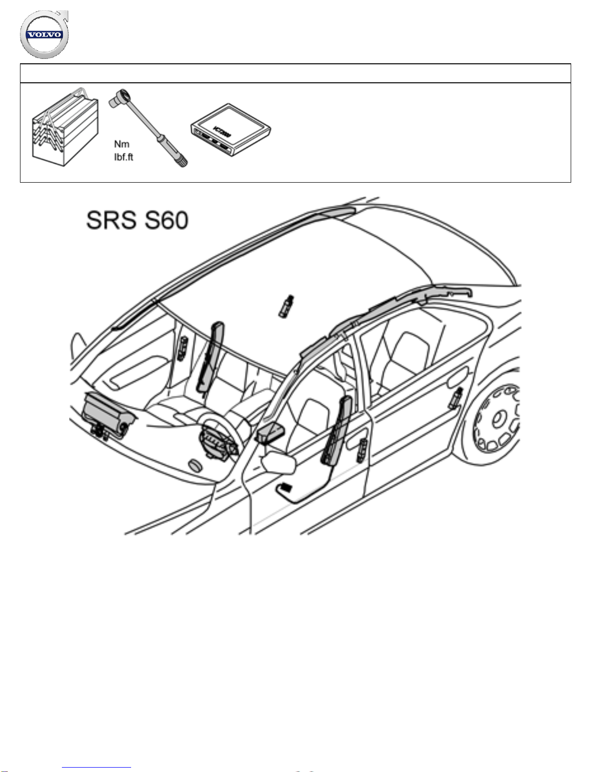
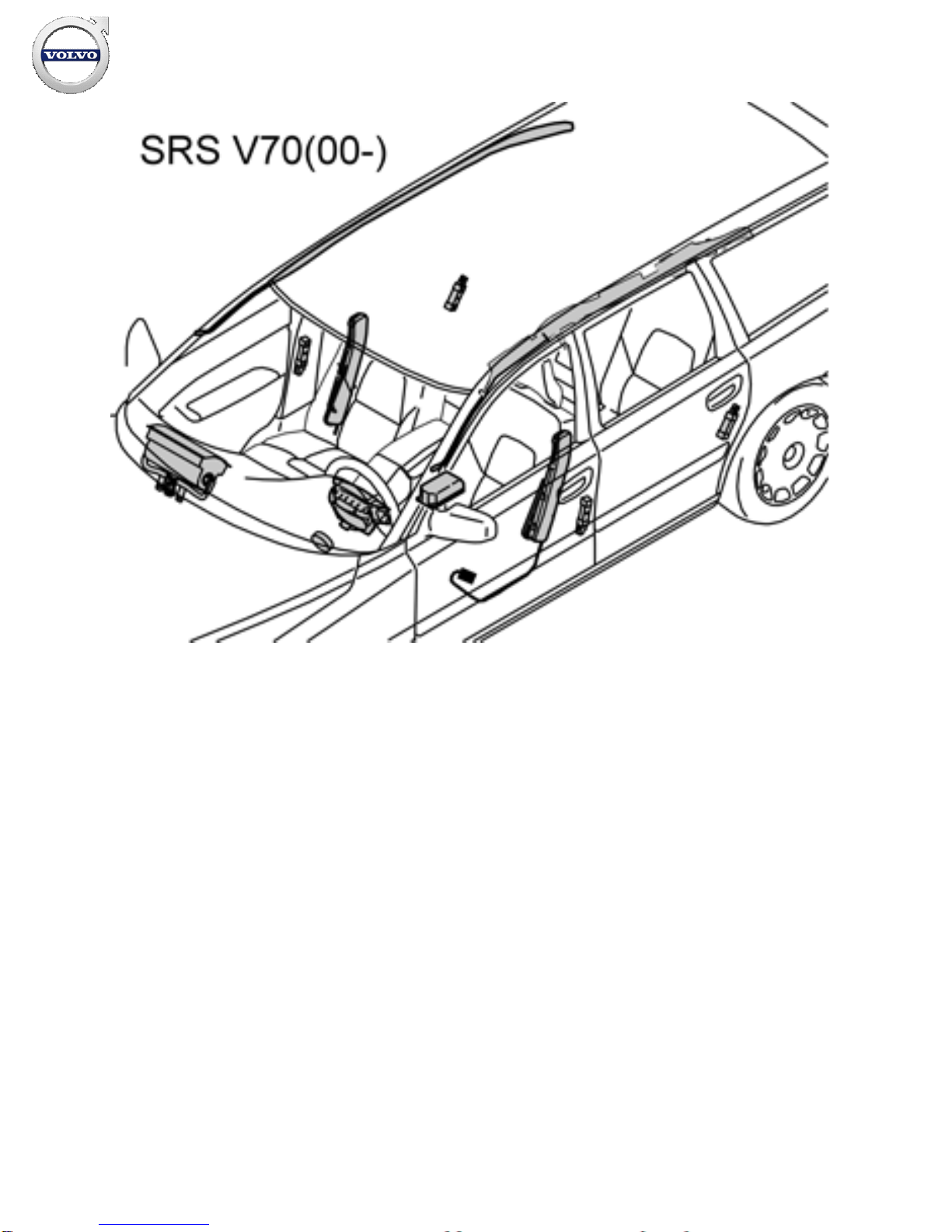
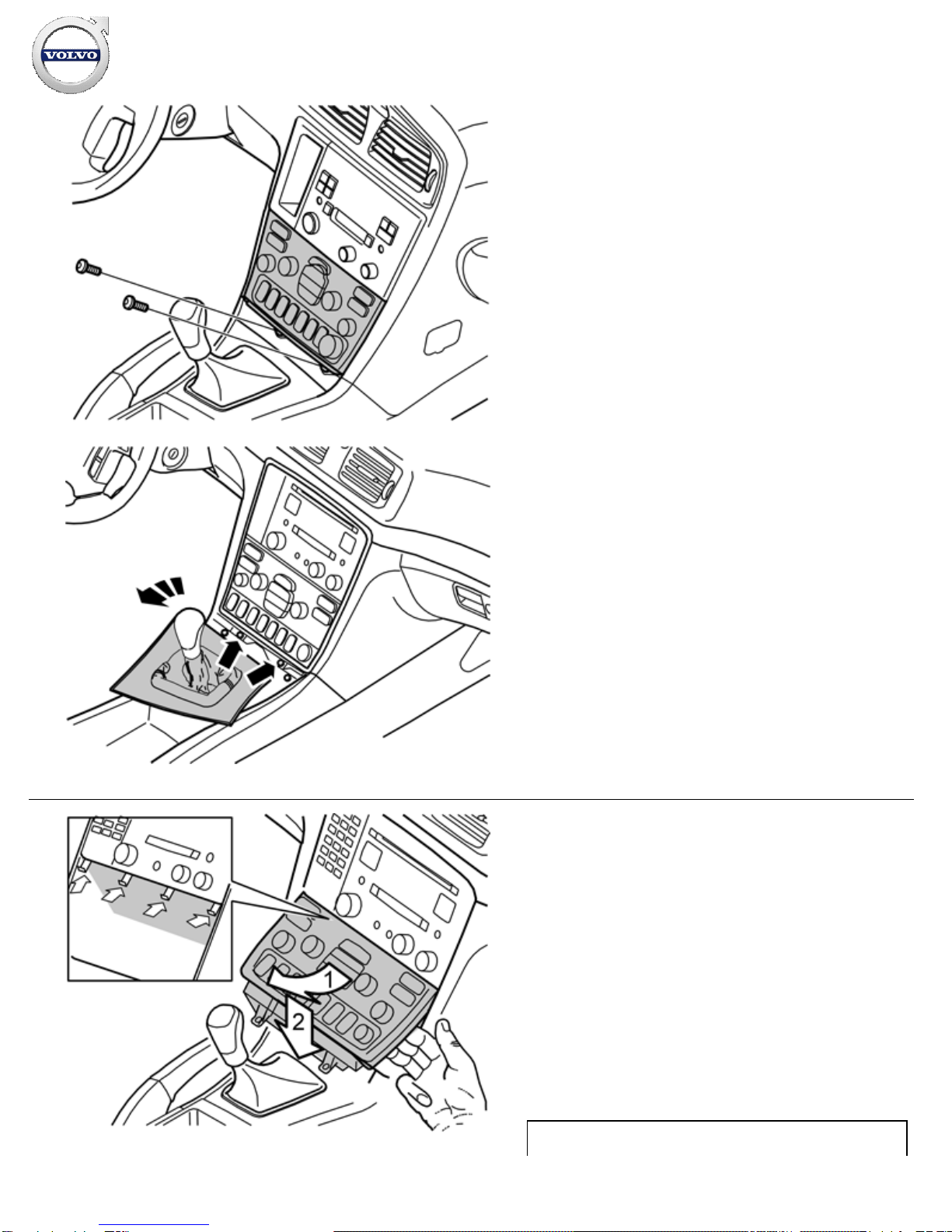
Certain steps in the instructions are only presented in the form
of images. Explanatory text is also given for more complicated
steps.
In the event of any problems with the instructions or the
accessory, contact your local Volvo dealer.
Note!
This accessory requires software unique to the car.
Note!
Steps 2-5 and 18 only apply to the S60, V70 and XC70.
Steps 6-9 and 19-20 only apply to the S80.
Preparations
1
A8800136
Preparations
Push the right
-hand front seat into the centre position. Raise it to
the highest position.
Push the left-hand front seat into the rear position.
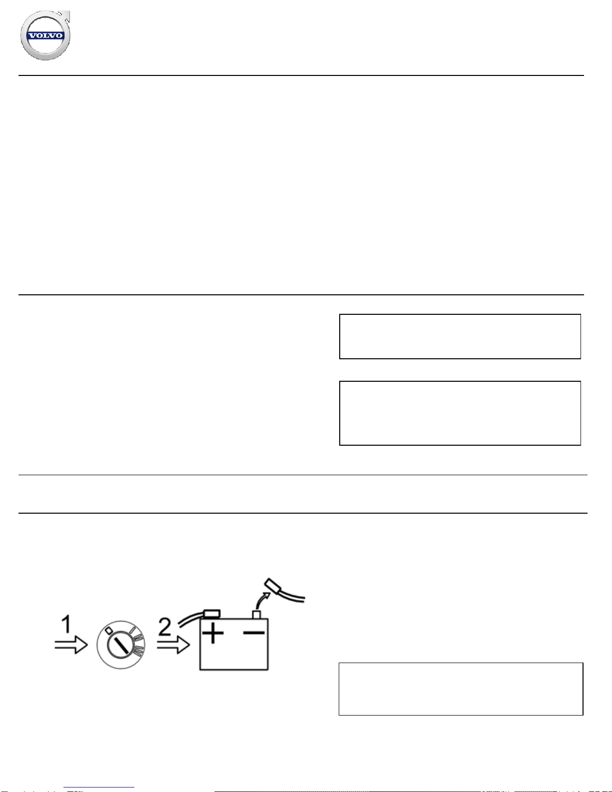
Turn the ignition key to position 0.
On cars with manual gearbox: Remove the ignition key.
Note!
Wait at least five minutes before disassembling the connectors
or removing other electrical equipment.
Disconnect the battery negative lead.
Installation instructions, accessories
Volvo Car Corporation Gothenburg, Sweden
©
Volvo Car Corporation Amplifier
-
30660636
-
V1.2
Page 8 / 20

Preparations S60/V70/XC70
2A
M8502988
2B
M8504883
Preparations S60/V70/XC70
Illustration A applies to cars up to and including model
year -
2004 (S60 CH
-424999, V70 CH -
458999, XC70 CH
-
172999)
Remove the cover panel in front of the gear selector lever by
prizing it away with a plastic weatherstrip tool as illustrated.
Move the gear selector lever as far back as possible.
Illustration B applies to cars from model year 2005-(
S60
CH 425000
-, V70 CH 459000-,
XC70 CH 173000
-)
Carefully prize away the gear selector lever cover panel
together with the boot until the two clips release. Use a plastic
weatherstrip tool. Pull the panel up until the four clips at the sides
release.
Installation instructions, accessories
Volvo Car Corporation Gothenburg, Sweden
©
Volvo Car Corporation Amplifier
-
30660636
-
V1.2
Page 9 / 20

3A
M8503027
3B
M8504884
Illustration A applies to cars up to and including model
year -
2004 (S60 CH
-424999, V70 CH -
458999, XC70 CH
-
172999)
Remove the two screws from the dashboard environment panel.
Illustration B applies to cars from model year 2005-(
S60
CH 425000
-, V70 CH 459000-,
XC70 CH 173000
-)
Engage the handbrake and move the gear selector lever towards
the rear.
Rotate the panel to the left for better access.
Remove the two screws holding the bracket with the radio and
dashboard environment panel in the centre console.
4A
M8503045
Illustration A applies to cars up to and including model
year -
2004 (S60 CH
-424999, V70 CH -
458999, XC70 CH
-
172999)
Angle the dashboard environment panel outwards so that it is
possible to insert a couple of fingers between the centre
console and the short side of the dashboard environment panel.
Pull the dashboard environment panel downward maintaining the
same angle and remove the dashboard environment panel. The
panel is well secured, so some force is required to detach the
panel.
Unplug the connectors on the reverse of the dashboard
environment panel, and place it to one side.
Note!
Installation instructions, accessories
Volvo Car Corporation Gothenburg, Sweden
©
Volvo Car Corporation Amplifier
-
30660636
-
V1.2
Page 10 / 20

4B
M8504890
If any of the outer hooks fail then this must be rectified. See the
section on the dashboard in the Workshop Manual in VIDA.
Illustration B applies to cars from model year 2005-(
S60
CH 425000
-, V70 CH 459000-,
XC70 CH 173000
-)
Remove the bracket with dashboard environment panel and the
radio from the centre console: Pull the lower edge out and
downwards until it releases from the mounting at the upper
edge. Then fold backwards.
Note!
Do not damage the removed components or the surrounding
panels.
If necessary, the panel around the gear lever selector can be
removed for additional space. The panel is secured with four
catches on the underside along the boot.
Unplug the connectors from the radio and dashboard
environment panel, and from the telephone keypad if applicable.
Place the unit to one side.
5
M3903036
Applies to cars up to and including model year -2004 (S60
CH
-424999, V70 CH -
458999, XC70 CH
-172999)
Remove the screws (1) from the bracket for the radio.
Pull the bracket with the radio outwards at the lower edge, and
pull the whole unit downwards.
Unplug the connectors from the radio.
Remove the radio.
Preparations S80
Installation instructions, accessories
Volvo Car Corporation Gothenburg, Sweden
©
Volvo Car Corporation Amplifier
-
30660636
-
V1.2
Page 11 / 20

6
R8504614
Preparations S80
Detach the panel (1). Detach the gear selector lever boot using a
weatherstrip tool.
7
D8504610
Move the gear selector lever to its rearmost position.
Pull the panel (1) with the boot backwards as far as possible.
Turn the panel as illustrated.
Remove the screws (2) holding the dashboard environment
panel (3).
Installation instructions, accessories
Volvo Car Corporation Gothenburg, Sweden
©
Volvo Car Corporation Amplifier
-
30660636
-
V1.2
Page 12 / 20

8
D8703093
Angle the dashboard environment panel outwards so that it is
possible to insert a couple of fingers between the centre
console and the short side of the dashboard environment panel.
Pull the dashboard environment panel downward maintaining the
same angle and remove the dashboard environment panel. The
panel is well secured, so some force is required to detach the
panel.
Disconnect the connectors on the reverse of the dashboard
environment panel. Place the dashboard environment panel to
one side.
Note!
If any of the outer hooks fail then this must be rectified. The
method for this is described in the Workshop Manual in the
section on the dashboard.
9
D8502109
Remove the screws (1) from the bracket for the radio.
Pull the bracket with the radio outwards at the lower edge, and
push the whole unit downwards.
Unplug the connectors from the radio.
Remove the radio.
Applies to all models: Installing the amplifier
Installation instructions, accessories
Volvo Car Corporation Gothenburg, Sweden
©
Volvo Car Corporation Amplifier
-
30660636
-
V1.2
Page 13 / 20

10
D8502110
Applies to all models: Installing the amplifier
Remove the covers (1) for the screws to the right-hand seat.
Remove the screws (2) from the seat base.
Unplug the connectors under the seat.
Tip the seat back.
11
D8502111
Remove the panel (1) on the right
-hand side of the centre
console. Turn the clip at the rear edge of the panel through 90°.
Pull the rear edge of the panel outward and backward.
Remove the sill moulding (2) at the right
-hand front door.
Detach the carpet (3), by the front left mounting for the right-
hand seat. Pull the carpet forward and to the right.
Fasten up the carpet in the door stop with a cord.
Fold the rear carpet (4) backwards at an angle.
Installation instructions, accessories
Volvo Car Corporation Gothenburg, Sweden
©
Volvo Car Corporation Amplifier
-
30660636
-
V1.2
Page 14 / 20

12
D3902150
Connect the thick cable harness from the kit to the sockets in the
amplifier.
If there is a pre-routed cable (2) to the power supply under the
right-hand seat, connect it and then skip over steps 14 -17. If
not, connect the cable from the kit for the power supply to the
amplifier.
Install the amplifier with the two enclosed screws (1) and
tighten.
Route the power supply positive cable together with the cable
harness running to the radio cut-out.
13A
D3702171
13B
D3701490
Illustration A applies to the S60/V70/XC70
Route the cable harness:
under the cut-away tab (1) of the carpet at the left-hand front
mounting for the right-hand seat.
over the left-hand air duct (2), along the lower edge of the
centre console and on, in front of the air ducts (3) up to the
dashboard environment panel cut-out. Following which, continue
on to the radio cut-out.
Illustration B applies to the S80
Route the cable harness:
under the cut-away tab (1) of the carpet at the left-hand front
mounting for the right-hand seat.
over the left-hand air duct (2), along the lower edge of the
centre console and on, between the air ducts (3) up to the
dashboard environment panel cut-out. Following which, continue
on to the radio cut-out.
Secure at the points (4).
Installation instructions, accessories
Volvo Car Corporation Gothenburg, Sweden
©
Volvo Car Corporation Amplifier
-
30660636
-
V1.2
Page 15 / 20

14
D3701661
Route the ground lead (1) for the power supply (brown) under
the carpet in the rear edge of the member for the front seat
mounting, out to the right
-hand side of the door sill.
Route the cable under the existing cable harness on to the
brown cable in the ground terminal at the front door pillar.
Connect the cable to the frame (2).
Clamp the cable together with the cable harness at the seat
mounting member (3) and at the front door pillar (3).
15
M8503528
Remove the panel (1) on the left
-hand side of the centre console.
Turn the clip at the rear edge of the panel through 90°, and pull
the rear edge of the panel outward and backward.
Remove the soundproofing panel (2) by removing the two
screws (3) and then prizing down the rear edge until the three
clips release.
Installation instructions, accessories
Volvo Car Corporation Gothenburg, Sweden
©
Volvo Car Corporation Amplifier
-
30660636
-
V1.2
Page 16 / 20

16
D3703402
Note!
On right
-hand drive cars the fuse holder is located on the right-
hand side. The positive cable is then routed the same way as
the ground lead, and up from below along the A-
pillar to the
fuse holder.
Remove the fuse holder cover.
Remove the fuse holder (1) by prizing up the catch at the top and
pulling outwards.
Route the amplifier's positive cable from the radio cut-
out behind
the dashboard to the fuse holder.
Route the cable down to the cable harness under the steering
column. Clamp the cable and the cable harness with a tie strap.
Route the cable to the left along the floor lighting cable and clamp
these with a tie strap.
Route the cable up to the fuse holder.
Applies to cars up to and including model year -2004 (S60
CH
-424999, V70 CH -
458999, XC70 CH
-
172999, S80 CH
-
389999)
Connect the cable to position 17 on the rear of the fuse holder.
Applies to cars from model year 2005-(
S60 CH 425000
-,
V70 CH 459000-,
XC70 CH 173000
-,
S80 CH 390000
-)
Connect the cable to position 11 on the rear of the fuse holder.
Applies to all models
Reinstall the fuse holder.
Installation instructions, accessories
Volvo Car Corporation Gothenburg, Sweden
©
Volvo Car Corporation Amplifier
-
30660636
-
V1.2
Page 17 / 20

17
D3702173
Applies to cars up to and including model year -2004 (S60
CH
-424999, V70 CH -
458999, XC70 CH
-
172999, S80 CH
-
389999)
Install a 30A fuse in position 17.
Applies to cars from model year 2005-(
S60 CH 425000
-,
V70 CH 459000-,
XC70 CH 173000
-,
S80 CH 390000
-)
Install a 30A fuse at position 11.
Applies to all models
Refit the fuse holder cover.
Connection and finishing work S60/V70/XC70
18
Connection and finishing work S60/V70/XC70
Applies to cars up to and including model year -2004 (S60
CH
-424999, V70 CH -
458999, XC70 CH
-172999)
Take the radio to the radio compartment and connect the grey
connector from the amplifier to the grey connector which was
detached from the radio.
Connect the other connectors to the radio.
Plug in the connectors for the phone keypad, if applicable.
Reinstall the bracket with the radio and secure it with the
screws.
Plug in the connectors to the dashboard environment panel.
Reinstall the dashboard environment panel.
Reinstall the panel in front of the centre gear selector lever.
Applies to cars from model year 2005-(
S60 CH 425000
-,
V70 CH 459000-,
XC70 CH 173000
-)
Connect the grey connector from the amplifier to the grey
connector which was detached from the radio.
Connect the other connectors to the radio.
Plug in the connectors to the dashboard environment panel.
Plug in the connectors for the phone keypad, if applicable.
Reinstall the unit with radio and dashboard environment panel in
the centre console. Tighten with the two screws.
Reinstall the panel around the gear selector lever
Installation instructions, accessories
Volvo Car Corporation Gothenburg, Sweden
©
Volvo Car Corporation Amplifier
-
30660636
-
V1.2
Page 18 / 20

Applies to all models
Reinstall the carpets.
Plug in the connectors to the seat and reinstall it.
Screw in four new screws to the seat frame, tightening torque
40 Nm (30 lbf.ft.).
Reinstall the covers over the seat screws.
Reinstall the soundproofing panel.
Reinstall the centre console's panels.
Reinstall the sill moulding.
Connection and finishing work S80
19
D8502112
Connection and finishing work S80
Plug in the connectors for loudspeakers, amplifier and antenna to
the radio.
When connecting the grey connector from the amplifier, take the
grey connector to the loudspeakers out from the radio. The two
connectors are plugged in to each other. The loudspeaker socket
in the radio is not used.
Push the radio into its cut
-out.
Press up the radio so that the groove in the top of the bracket
encloses the top edge of the radio cut-
out. At the same time,
angle the radio down so that the bracket's lower mountings are
pressed against the lower edge of the radio cut-out.
Screw in the two screws (1) in the lower mountings and tighten.
20
Reinstall the panel around the gear selector lever
Plug in the connectors and reinstall the dashboard environment
panel.
Reinstall the carpets.
Plug in the connectors to the seat and reinstall the seat.
Screw in four new screws from the kit to the seat frame,
tightening torque 40 Nm (30 lbf.ft.).
Reinstall the covers over the seat screws.
Reinstall the soundproofing panel.
Reinstall the centre console's panel.
Installation instructions, accessories
Volvo Car Corporation Gothenburg, Sweden
©
Volvo Car Corporation Amplifier
-
30660636
-
V1.2
Page 19 / 20

Reinstall the sill moulding.
Applies to all models
21
A8800137
Applies to all models
Turn the ignition key to position II.
Reconnect the battery negative lead
Programme the software in accordance with the service
information in VIDA.
Note!
The software download is carried out in the following order
depending on whether the accessories HU radio and amplifier
have been installed at the same time, or if just the amplifier has
been installed.
Applies if both HU radio (AUM) and amplifier have been
installed:
First download ADD AMPLIFIER.
Then download ADD AUM.
Applies if only amplifier has been installed (existing HU
radio):
First download ADD AMPLIFIER.
Then download RELOAD AUM / UPGRADE AUM. This is so that
the radio shall obtain the correct software in combination with
the new amplifier.
Hint
If the downloads are made in the wrong order then repeat
RELOAD AUM / UPGRADE AUM.
Installation instructions, accessories
Volvo Car Corporation Gothenburg, Sweden
©
Volvo Car Corporation Amplifier
-
30660636
-
V1.2
Page 20 / 20
This manual suits for next models
2
Other Volvo Amplifier manuals