Technical solutions
Cylinder block and lower
crankcase
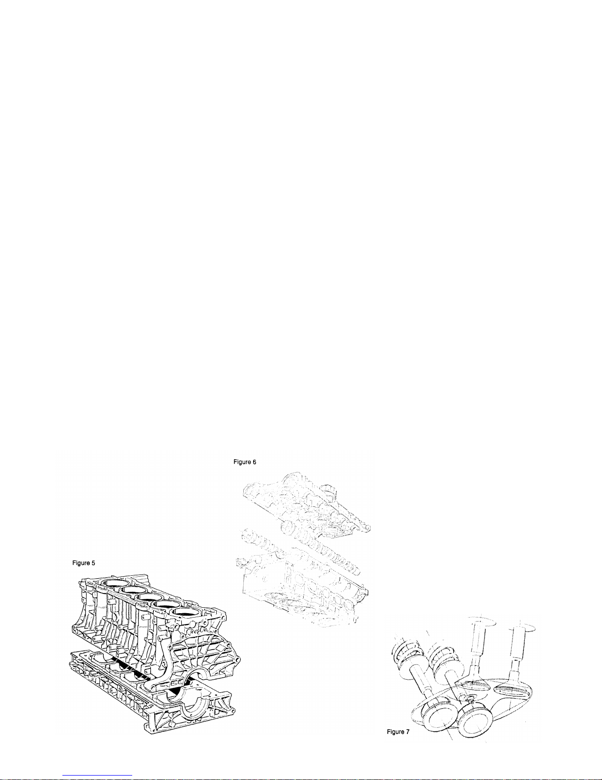
Figure 5
The cylinder block and lower crank-
case are manufactured of high-
pressure die-cast aluminium. Based on
FEM (Finite Element Method) analy-
sis and simulation, the block has been
designed to produce a compact and
rigid engine, featuring extremely low
noise and vibration emissions. The
lower crankcase, with its integrated
cast-in reinforcements in the main
bearing caps, and cylinder block to-
gether form a very compact and rigid
unit. Furthermore, the walls of both
sections have been given a reinforced
ribbing structure in order to minimize
panel vibrations and the transmission
of noise.
The grey iron cylinder liners are
cast-in during the high-pressure die-
cast process of the cylinder block. The
liners offer high wear resistance and
reduce the risk for leaks. The pro-
duction process is also cost-effective
and environmentally friendly.
The slots between the cylinders at
the upper edge of the block have been
specially machined to minimize the
risk for ovality in the cylinders as a
result of thermal expansion.
The lower crankcase has re-
inforcements of cast nodular iron in
the main bearing caps. This mini-
mizes the increase of clearance in the
main bearing that can be caused by
thermal expansion.
During the manufacturing process,
the main bearing bores are machined
with the block and the lower crank-
case bolted together as one unit. In or-
der to ensure that the unit is tight and
stable, a liquid gasket is applied be-
t
ween the two parts. They are then
joined to each other with yield-point
tightened bolts during final assembly.
Oil channels and coolant ducts are
cast in during the production of block
and lower crankcase. This obviates
the need for subsequent drilling and
machining of the channels. This de-
sign principle is very cost-effective
and well suited for series production.
Cylinder head and cam-
shaft bearing housing
Figure 6
The cylinder head is made of chill-
cast aluminium to ensure a homog-
enous material. The combustion
chambers is of the pent-roof type with
four valves per cylinder. The valves
are set at a relative angle of 58 de-
grees and flank the centrally located
spark plug (figure 7). By selecting
this valve angle it has been possible to
obtain an extremely compact combus-
tion chamber, allowing for coolant
ducts between the valves and the
spark plug.
The camshaft bearing housing has
integrated upper bearing halves and
forms the top part of the cylinder
head. The lower bearing halves are in-
tegrated in the cylinder head.
The camshaft bore is machined
with the camshaft bearing housing
and cylinder head assembled. In final
assembly, a liquid gasket is applied
between both parts in order to obtain
a tight and stable joint. Oil and cool-
ant ducts are produced in the same
way as with block and lower crank-
case.
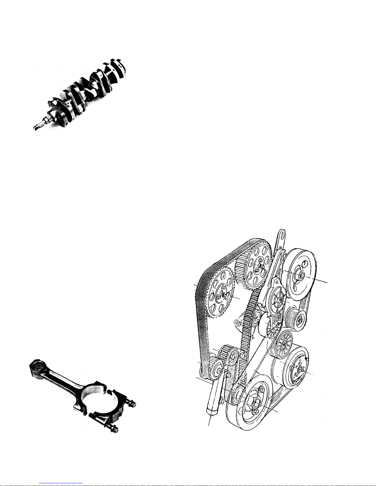
The double overhead camshafts
and cam profiles have been designed
with the aid of computer calculations
and simulations in order to minimize
torsional vibrations in the camshaft
while at the same time retaining ex-
cellent gas flow properties. The cams
offer maximum 8.45 mm lift. At 0.1
mm lift the overlap is 24 crankshaft
degrees between the exhaust valve
closing and the inlet valve opening.
Valve diameters are 31 mm for in-
let valves and 27 mm for exhaust
valves. The valve stems are chro-
mium-plated and has a 7 mm dia-
meter.
The valve guides are cast iron. Hy-
draulic maintenance-free valve tap-
pets are used.
The cylinder head is bolted to the
cylinder block with yield-point tight-
ened bolts and a head gasket which,
like all other gaskets in the engine, is
asbestos-free.