The information is developed by ©Volvo Group in Sweden. 10
VOCOM II can be used for a period of about 15 years, provided that regular maintenance and
testing ensure safe operation.
Non-intended use (foreseeable misuse):
Avoid the following listed areas of misuse:
Opening VOCOM II.
Careless handling of VOCOM II.
Careless handling of cables used with VOCOM II.
Use of defective cables.
Use of unauthorized cables.
Exceeding the permissible operating voltage of VOCOM II.
Use of incorrect regional settings in WLAN mode.
Use other than under the specified conditions and requirements laid out by the
manufacturer in its technical documents, data sheets, assembly, installation and operation
instructions and in other specific regulations.
Warnings3.3
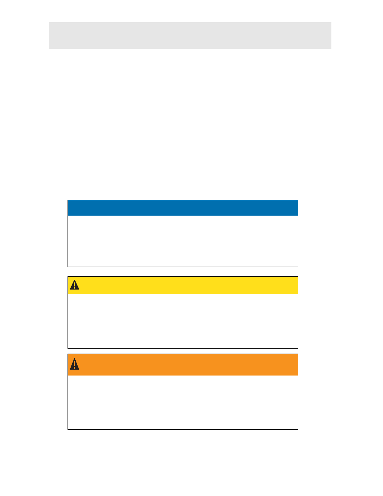
NOTICE
Possible material damage due to removal of protectors!
The device and the materials can be damaged if the front protector and
WLAN protector are removed during transport.
Keep the front protector and WLAN protector fitted on the device when
preparing VOCOM II for transport.
CAUTION
Risk of slight injuries due to careless handling of cables.
There is risk of slight injuries in case of careless handling of cables used with
VOCOM II.
Do not pull the cables.
Make sure that cables do not run across the floor.
WARNING
Serious injuries due to improper maintenance work!
Improperly performed maintenance work can impair the safety of the device
and cause serious injuries.
Only allow authorized and instructed personnel to perform maintenance
work.