Vostermans Ventilation MASTER-5N Parts list manual

MASTER-5N
ENGLISH
Installation Instructions - Operating Instructions
NEDERLANDS
Installatie Instructies - Gebruiksaanwijzing
DEUTSCH
Installationsanleitung - Betriebsanleitung
IMPORTANT - READ CAREFULLY BEFORE USE
BELANGRIJK - VOOR GEBRUIK ZORGVULDIG LEZEN
WICHTIG - VOR GEBRAUCH SORGFÄLTIG LESEN
Document ID: INS00110-A

2
INS00110-A
Table of Contents
English.................................................................................................................................... 3
Nederlands..............................................................................................................................16
Deutsch...................................................................................................................................
28

INS00110-A
Original instructions
ENGLISH | 3
MASTER-5N
1Introduction ...........................................................................................................................................................................................................3
2Safety ....................................................................................................................................................................................................................4
3Information ............................................................................................................................................................................................................5
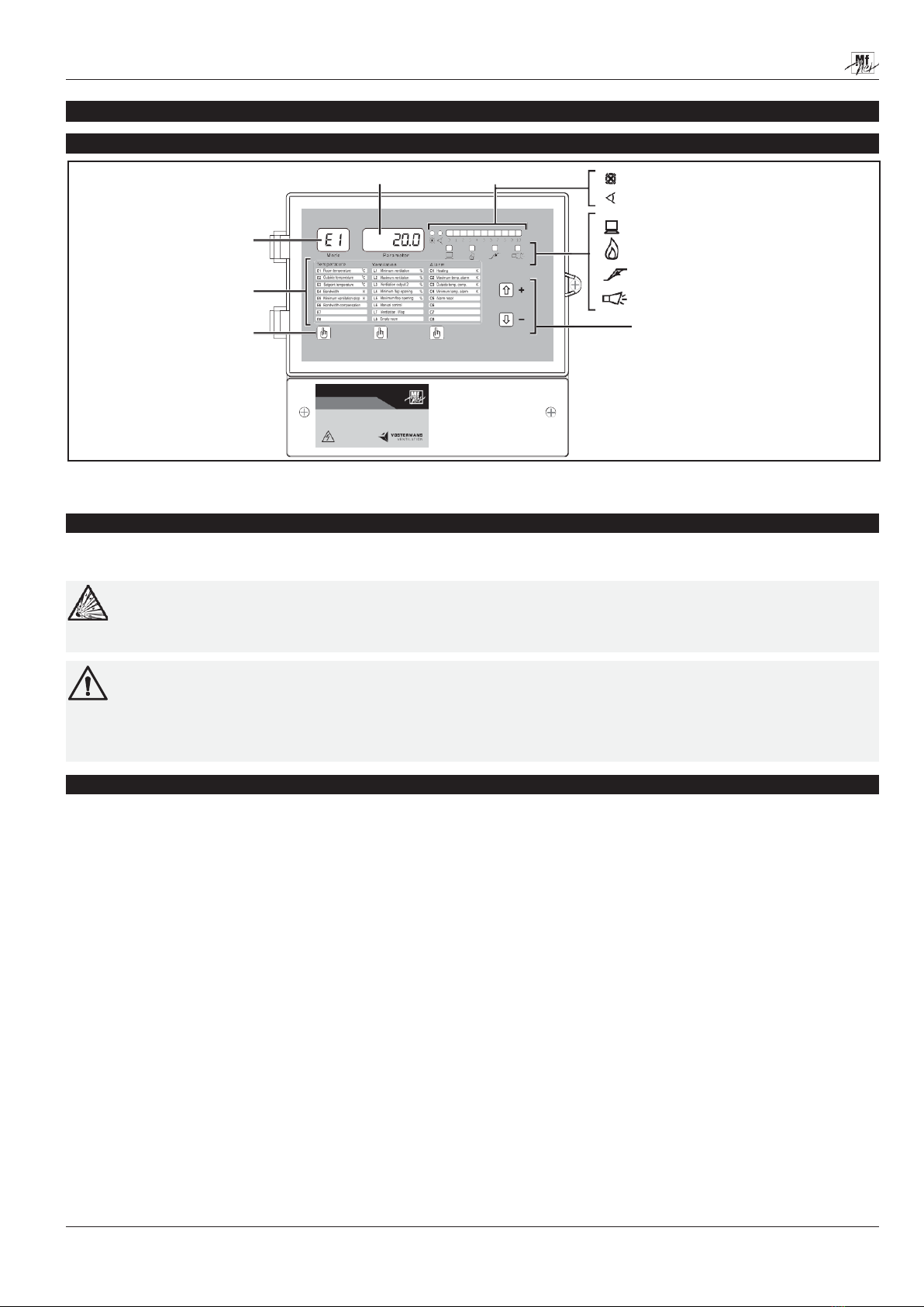
3.1 Overview.......................................................................................................................................................................................................5
3.2 Intended use .................................................................................................................................................................................................5
3.3 Technical Information .....................................................................................................................................................................................5
4Installation .............................................................................................................................................................................................................6
4.1 Mechanical....................................................................................................................................................................................................6
4.2 Electrical .......................................................................................................................................................................................................6
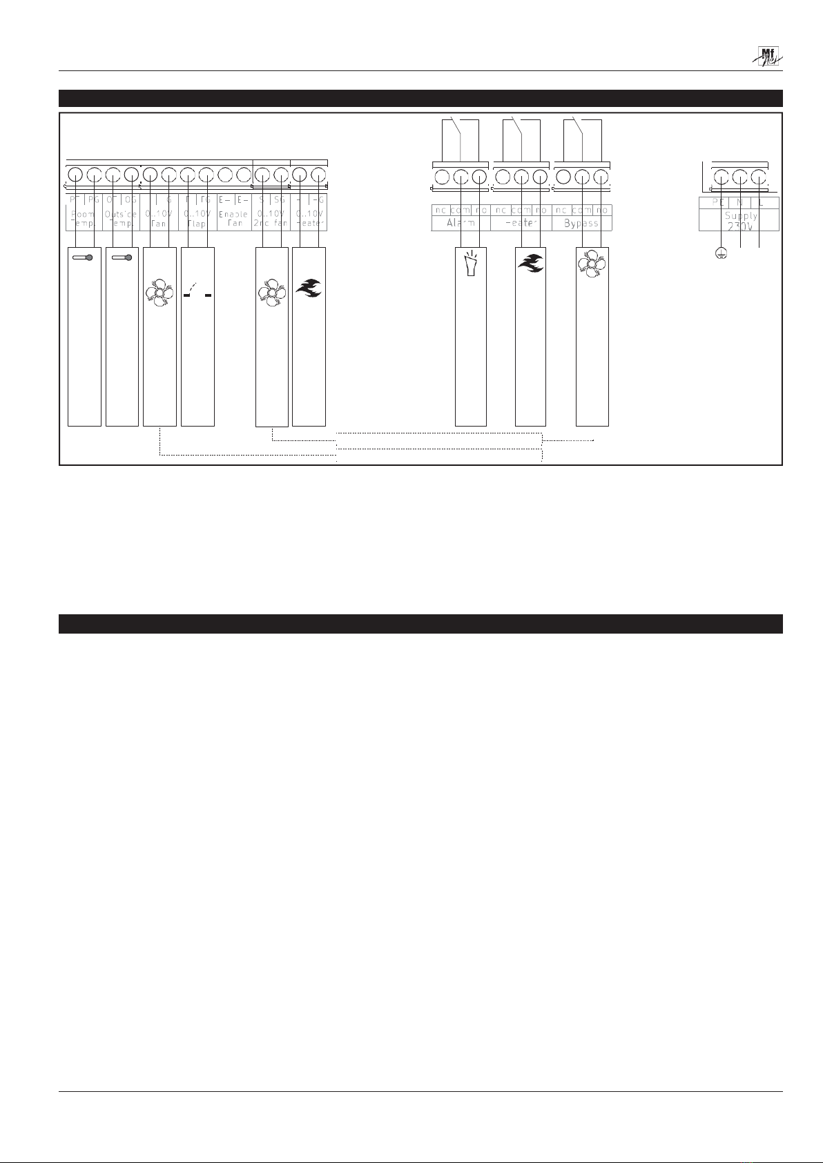
4.3 Wiring diagram ..............................................................................................................................................................................................7
5Settings .................................................................................................................................................................................................................7
5.1 General settings list........................................................................................................................................................................................8
5.2 Advanced settings list.....................................................................................................................................................................................8
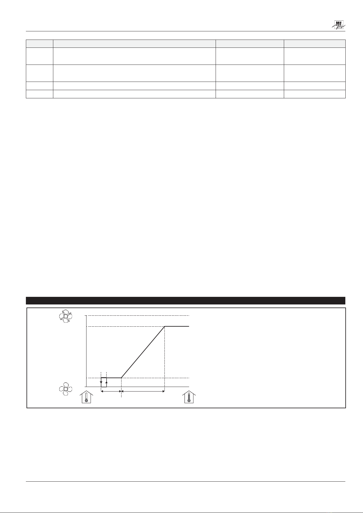
5.3 Ventilation level .............................................................................................................................................................................................9
5.4 Bandwidth compensation ..............................................................................................................................................................................11
5.5 Air inlet flap .................................................................................................................................................................................................12
5.6 Heating.......................................................................................................................................................................................................12
5.7 Manual control.............................................................................................................................................................................................12
5.8 Empty room.................................................................................................................................................................................................12
5.9 Temperature alarms.....................................................................................................................................................................................13
6Operation.............................................................................................................................................................................................................13
6.1 Alarm..........................................................................................................................................................................................................13
7Maintenance.........................................................................................................................................................................................................14
8Troubleshooting...................................................................................................................................................................................................14
9End of life ............................................................................................................................................................................................................14
Glossary ..............................................................................................................................................................................................................15
IMPORTANT: READ THESE INSTRUCTIONS CAREFULLY BEFORE USE
KEEP THESE INSTRUCTIONS FOR FUTURE REFERENCE
These instructions are a part of this product and must be passed on to any subsequent owner and/or user.
Contact your supplier if there are parts of these instructions that you do not understand. Compliance with these instructions will ensure a safe and correct use of
this product.
Legal notice / Disclaimer
The scope of delivery may vary from product images shown. This document was created with all due care. The information, instructions and parts listed are
current on the date this document was issued.
Improper use
No liability is accepted for damages resulting from improper use.
Packaging
If packaging materials are no longer required, dispose of them in accordance with regulations that apply in your area.
Table of Contents
1 Introduction
NOTICE
This product is for professional use only.

MASTER-5N
4 | ENGLISH
Original instructions
INS00110-A
Manufacturer:
This product is manufactured for Vostermans Ventilation B.V. by:
es-electronic UG
Brandenburger Straße 7
D-89287 Bellenberg
Germany
es-electronic UG is legally the manufacturer.
Safety messages
Your safety and the safety of others are very important. Important safety messages are provided in these instructions.
READ THESE MESSAGES CAREFULLY
A safety message alerts you to potential hazards that could hurt you or others. Each safety message is preceded by a safety symbol and one of four signal
words: DANGER, WARNING, CAUTION or NOTICE.
Explanation of the signal words used in these instructions
DANGER : You will be killed or seriously hurt if you do not follow instructions.
WARNING : You can be killed or seriously hurt if you do not follow instructions.
CAUTION : You can be hurt if you do not follow instructions.
NOTICE : Is used to address practices not related to physical injury.
Explanation of the safety symbols used
General warning symbol
Warning for electricity
Warning for hot surfaces
Warning for automatic activation
Warning for explosive materials
General mandatory action sign
2 Safety

MASTER-5N
INS00110-A
Original instructions
ENGLISH | 5
Value of the selected setting Status bar Ventilation level shown in status bar
Air inlet flap opening shown in status bar
This LED is not used.
Selected setting Heater
Bandwith compensation
General settings list Alarm
Setting selection buttons Adjust setting value
MASTER-
5N
The settings list on the controller is default in English. Labels to change the settings list to Dutch, German or French are included with the controller. The
controller display language is English and this cannot be changed.
The MASTER-5N is a room temperature controller. The MASTER-5N controls room temperature by controlling ventilation, heating and air inlet flaps. Ventilation,
heating and air inlet flaps are controlled using 0-10 V outputs to be connected to external control units.
General
Power supply 230 VAC 50/60 Hz ±10%
Power consumption 25 VA no load
Fuse T 200 mA
Ambient operating temperature range -10 °C < x < 40 °C
Ambient relative humidity ≤95% non-condensing
Degree of Ingress Protection IP54
Weight / Dimensions 2.0 kg / 267 x 225 x 104 mm
Inputs
Temperature sensors KTY81/110 PTC (1KΩ @ 25°C)
Relay outputs
Alarm relay contact (SPDT) Max. 2 A - 250 VAC / Min. 12 V - 10 mA
Ventilation output 2 relay contact (SPDT) Max. 2 A - 250 VAC / Min. 12 V - 10 mA
Heating relay contact (SPDT) Max. 2 A - 250 VAC / Min. 12 V - 10 mA
Analogue outputs
Ventilation output 1 0-10 V / 10-0 V Max. 10 mA
Ventilation output 2 0-10 V / 10-0 V Max. 10 mA
Air inlet flap output 0-10 V / 10-0 V Max. 10 mA
Heating output 0-10 V / 10-0 V Max. 10 mA
3 Information
3.1 Overview
3.2 Intended use
DANGER
Do not use this product in explosive or potentially explosive atmospheres .
DANGER
Where the health and well-being of humans and/or animals is dependent on the functioning of this controller, an appropriate backup system
must be provided such that in the event of failure of the controller, sufficient air renewal is guaranteed to preserve the health and well-being
of the humans and/or animals.
3.3 Technical Information

MASTER-5N
6 | ENGLISH
Original instructions
INS00110-A
►Before commencing installation
1. Check the product after you have received it and make sure it has not been damaged during transport.
2. Check all the information on the rating plate and verify that this product is suitable for the intended application.
4.1 Mechanical
NOTICE
This product must be installed on a non-flammable surface
NOTICE
This product must be installed vertically with the cable entry openings pointing downwards
NOTICE
To ensure adequate cooling of the controller, make sure there is at least 100mm clearance around the controller.
NOTICE
Do not install this product inside an electrical enclosure.
NOTICE
To avoid damage by corrosive gasses: When used in livestock buildings, do not install this product directly inside the rooms where animals
and/or manure are present.
Check the rating plate and verify that this product is suitable for the available power supply.
Use the cable grommets supplied with this product.
Isolator
This product is supplied without an electrical isolator. An electrical isolator must be provided to facilitate safe maintenance and troubleshooting.
Grounding
This product must be grounded.
4 Installation
Electrical
4.2
NOTICE
Electrical connection must be carried out by a qualified electrician. Electrical connections must be made in accordance with local regula-
tions.
WARNING
Even when the controller itself is isolated from the power supply, there can still be power on the terminals where the external equipment is
connected.

MASTER-5N
INS00110-A
Original instructions
ENGLISH | 7
Illustration 1: Wiring diagram
The analogue ventilation output 2 and ventilation output 2 relay contact, are together referred to as ‘ventilation output 2”.
NOTICE! The relay contacts have no overcurrent protection.
Alarm relay contact
The alarm relay contact is active during normal operation (COM-NO closed). When there is an alarm or a power failure to the controller, the relay contact is
inactive (COM-NC closed).
There are two groups of settings, general settings and advanced settings. The general settings are for regular use. NOTICE! The advanced settings are
not for regular use, but are usually only needed during the installation of the controller.
General settings
The general settings are grouped in three subgroups and are listed on the control panel:
E - Temperature Settings
L - Ventilation settings
C –Heating and alarm settings
►Selecting and modifying a general setting:
1. Press the HAND button underneath the group until the required setting is shown in the MODE display.
2. Change the value of the setting which is shown in the PARAMETER display, by using the ARROW UP and ARROW DOWN buttons.
Advanced settings
The advanced settings are grouped in two subgroups:
H –Settings related to sensors and heating
P –Settings related to fans and air inlet flaps
►Selecting and modifying an advanced setting of group H:
1. Press and hold the HAND button underneath the temperature group.
2. Press the HAND button underneath the alarm group until the required setting is shown in the MODE display.
3. Change the value of the setting which is shown in the PARAMETER display, by using the ARROW UP and ARROW DOWN buttons.
►Selecting and modifying an advanced setting of group P:
1. Press and hold the HAND button underneath the temperature group.
2. Press the HAND button underneath the ventilation group until the required setting is shown in the MODE display.
4.3 Wiring diagram
NL
1~ 230 V 50/60 Hz
"Ventilation output 1"
"Ventilation output 2"
Room temperature sensor
Outside temperature sensor
0-10 V
GND
0-10 V
GND
Analogue ventilation output
1
Analogue air inlet flap
output
0-10 V
GND
0-10 V
GND
Analogue ventilation output
2
Analogue heating output
Alarm contact
Heating contact
Ventilation output 2 relay
contact
5 Settings

MASTER-5N
8 | ENGLISH
Original instructions
INS00110-A
3. Change the value of the setting which is shown in the PARAMETER display, by using the ARROW UP and ARROW DOWN buttons.
Display
When there has been no user interaction for one minute, the displays return to the default view showing the room temperature.
If there is an alarm, the displays show the alarm code instead of the room temperature.
Setting
Description
Selection range
Default value
E1
Room temperature
E2
Outside temperature
E3
Setpoint temperature
0 –40°C
20.0°C
E4
Bandwidth
2 –12 K
5 K
E5
“Minimum ventilation stop“ temperature
OFF/ -25 –0 K
OFF
E6
Bandwidth compensation
ON / OFF
OFF
L1
Minimum ventilation level
0 –50%
0%
L2
Maximum ventilation level
50 –100%
100%
L3
Ventilation output 2
OFF / 20 –80% / ON
OFF
L4
Air inlet flap minimum opening
0 –50%
0%
L5
Air inlet flap maximum opening
50 –100%
100%
L6
Automatic or manual control
Auto / Hand 0 –100%
Auto
L7
Select if ventilation level or air inlet flap opening is shown in the status bar
Ventilation level
L8
Empty room function
Auto / OFF
Auto
C1
Heating
OFF / -15 –0 K
OFF
C2
High temperature alarm
OFF / 0 –25 K
OFF
C3
Outside temperature alarm compensation
OFF / 0 –20 K
OFF
C4
Low temperature alarm
OFF / -20 –0 K
OFF
C5
Alarm reset
OFF / ALARM CODE
OFF
Setting
Description
Selection range
Default value
H1
Correction to the measured value of the room temperature sensor
±10 K
0 K
H2
Correction to the measured value of the outside temperature sensor
± 10 K
0 K
H3
Hysteresis of the ON-OFF heating contact
0.5 –10.0 K
1.0 K
H4
Minimum output level of the analogue heating output
0 –50%
(=0 –5 V or 5 –0 V)
0%
H5
Maximum output level of the analogue heating output
50 –100%
(=5 –10 V or 10 –5 V)
100%
H6
Bandwidth of the analogue heating output
0.5 K –6.0 K
2.0 K
H7
Inverting the analogue heating output
0 –10 V
10 –0 V
0 - 10 V
H8
This setting is not used.
H9
This setting is not used.
HA
Minimum ventilation cycle timer ON time
1 –100%
100%
P1
Minimum level of ventilation output 1 and 2
0 –30%
15%
For the analogue ventilation
output this is 1,5 V or 8,5 V
(inverted)
P2
Maximum level of ventilation output 1 and 2
70 –100%
100%
P3
Minimum output level of the air inlet flap analogue output
0 –30% (= 0 –3 V)
0%
P4
Maximum output level of the air inlet flap analogue output
70 –100% (= 7 –10 V)
100%
P5
This setting is not used.
P6
Inverting the analogue ventilation output 1
0 –10 V
10 –0 V
0 –10 V
5.1 General settings list
5.2 Advanced settings list

MASTER-5N
INS00110-A
Original instructions
ENGLISH | 9
Setting
Description
Selection range
Default value
P7
Inverting the analogue ventilation output 2
0 –10 V
10 –0 V
0 –10 V
P8
Inverting the analogue air inlet flap output
0 –10 V
10 –0 V
0 –10 V
P9
Offset between ventilation level and air inlet flap control
-99 –99% of bandwidth E4
0%
PC1
Low supply voltage alarm
ON/OFF
ON
1Available in software version 5.16 and higher
P1 - Minimum output voltage
With setting P1 the minimum output voltage of the analogue outputs is set.
When using electronic speed control (TRIAC), fans manufactured by Vostermans Ventilation B.V. must not be run at voltages lower than 40% of their rated
voltage. Adjust P1 so that fans manufactured by Vostermans Ventilation B.V. will operate at least at 40% of their rated voltage (92 Vrms at 230 V).
►To adjust P1 and set the required minimum output voltage, ventilation level must be temporarily set to minimum ventilation level:
►Note the values of settings L1, E5 and E3.
1. Set L1 to 0%
2. Set E5 to OFF
3. Set E3 > E1
Ventilation level is now at minimum ventilation level.
4. Adjust P1 until the required minimum output voltage is reached.
5. Restore L1, E5 and E3 to their original values.
P2 –Maximum output voltage
With setting P2 the maximum output voltage of the analogue outputs is set.
►To adjust P2 and set the required maximum output voltage, ventilation level must be temporarily set to maximum ventilation level:
►Note the values of settings L2 and E3.
1. Set L2 to 100%
2. Set E3 < ( E1 - E4 )
Ventilation level is now at maximum ventilation level.
3. Adjust P2 until the required maximum output voltage is reached.
4. Restore L2 and E3 to their original values.
100%
L2
L1 - Minimum ventilation level
L2 - Maximum ventilation level
hysteresis 0.5K E3 - Setpoint temperature
L1 E4 - Bandwidth
0% E5 - "Minimum ventilation stop" temperature
E5 E4
E3
Illustration 2: Ventilation level
Ventilation is based on the room temperature. With settings L1 and L2 minimum and maximum ventilation level are set. Setting E4 is the bandwidth over which
the ventilation increases from minimum L1 to maximum L2.
E5 –Minimum ventilation stop
Using setting E5, ventilation can be stopped completely if the room temperature drops too far below the setpoint temperature. E5 sets the negative offset to the
setpoint temperature at which ventilation must stop completely.
5.3 Ventilation level

MASTER-5N
10 | ENGLISH
Original instructions
INS00110-A
HA –Minimum ventilation cycle timer
NOTICE! The minimum ventilation cycle timer is available in devices with software version 5.11 or higher. The software
version is indicated on the rating plate and is briefly displayed when the device is switched on.
Minimum ventilation can run on a cycle timer cycling between L1 (ON) and 0% (OFF). This can be used to further reduce the minimum ventilation level for
example in a situation where the minimum fan speed is too high for the required ventilation level.
The total cycle time is 10 min / 600 s and this cannot be changed. With setting HA the ON time is set in % of the total cycle time. 1 % = 6 s.
The cycle timer is operating when HA = 1 - 99 and the room temperature is between E5 (“minimum ventilation stop” temperature) and E3 (setpoint temperature).
When HA = 100 and the room temperature is between E5 and E3 the cycle timer is not operating.
When E5 = 0 K the cycle timer is not operating.
The ventilation LED blinks when the cycle timer is operating.
10 min
L1 - Minimum ventilation level
HA
HA - Cycle ON time (1 % = 6 s)
L1 (ON)
0% (OFF)
t
Illustration 3: Minimum ventilation cycle timer
L3 - Ventilation output 2
100%
L2 L1 - Minimum ventilation level
L2 - Maximum ventilation level
L3 - Ventilation output 2
L1 Ventilation output 1 - L3 = 20 - 80%
0% E3 - Setpoint temperature
E4 - Bandwidth
E4
E3 L3 x E4
100%
L2 L1 - Minimum ventilation level
L2 - Maximum ventilation level
L3 - Ventilation output 2
Analogue ventilation output 2 - L3 = 20 - 80%
L1
0% E3 - Setpoint temperature
E4 - Bandwidth
E4
E3 L3 x E4
ON
OFF Relay contact ventilation output 2 - L3 = 20 - 80%
E4
E3 L3 x E4
Illustration 4: Ventilation output 2 - [20 - 80%]
An additional analogue output and relay contact for ventilation are present. Setting L3 can be set to ON, OFF or a percentage of the bandwidth E4 from 20 -
80%.
When setting L3 is set to OFF the relay contact will always be inactive. When setting L3 is set to ON, the relay contact will be active when the required
ventilation level is 0% or higher. Ventilation output 1 and 2 will follow the bandwidth E4.
When a percentage of the bandwidth E4 from 20 –80% is set, ventilation will be according to the graph above.

MASTER-5N
INS00110-A
Original instructions
ENGLISH | 11
E4 × 1,5
100%
L2
(L1+L2) / 2 L1 - Minimum ventilation level
L2 - Maximum ventilation level
hysteresis 0.5K E3 - Setpoint temperature
L1 E4 - Bandwidth
0% E5 - "Minimum ventilation stop" temperature
E5 E4
E3
Illustration 5: Bandwidth compensation
With setting E6 bandwidth compensation can be enabled or disabled. Bandwidth compensation prevents a too rapid decrease of the room temperature in
situations where the outside temperate drops rapidly for example during a thunderstorm.
When the room temperature rises above the bandwidth E4 × 1.5, bandwidth compensation will become active if enabled in setting E6. When bandwidth
compensation is active, ventilation level will be according to the graph above. The bandwidth compensation LED is ON when bandwidth compensation is active.
Bandwidth compensation will be deactivated when the room temperature drops below E4 × 0.5.
100%
L5
E3 - Setpoint temperature
E4 - Bandwidth
L4 L4 - Air inlet flap minimum opening
0% L5 - Air inlet flap maximum opening
E4
E3
Illustration 6: Air inlet flap opening [0 - 10 V]
Air inlet flap opening is controlled via an analogue 0 - 10 V output. Air inlet flap opening is based on the room temperature. With settings L4 and L5, minimum
and maximum air inlet flap opening are set.
P9 –Ventilation level and air inlet flap offset
Ventilation level and air inlet flap opening are parallel by default (they use the same setpoint temperature and bandwidth).
Setting P9 can be used to offset the ventilation level from the air inlet flap opening. This setting P9 can be used to open the air inlet flap ahead of the increase of
the ventilation level.
5.4 Bandwidth compensation
5.5 Air inlet flap

MASTER-5N
12 | ENGLISH
Original instructions
INS00110-A
ON E3 - Setpoint temperature
C1 - Heating start temperature
OFF H3 - Heating hysteresis
H3 C1 E3
Illustration 7: Heating [ON / OFF]
100%
H5
E3 - Setpoint temperature
C1 - Heating start temperature
H4 - Minimum heating
H4 H5 - Maximum heating
0% H6 - Heating bandwidth
H6 C1 E3
Illustration 8: Heating [0 - 10 V]
Heating can be controlled via a relay contact and/or an analogue 0 - 10 V output. Setting C1 sets the negative offset to the setpoint temperature at which the
heating must switch on. Setting H6 is the heating bandwidth.
With setting L6 ventilation level and air inlet flap opening can be controlled manually.
When manual control is active, ventilation level and air inlet opening can be set from 0 –100%. Ventilation level and air inlet flap opening are linked and cannot
be adjusted separately. Settings L1, L2, L4, L5 are ignored during manual control.
Exiting setting L6 automatically switches control back to automatic mode.
With setting L8 the empty room function can be enabled. The empty room function can be used when the room is not in use and no ventilation or heating is
required. All outputs excluding the heating outputs are disabled when the empty room function is enabled. All alarms are suppressed.
For frost protection, the heating function stays enabled and the heating outputs are activated if the room temperature drops below 3 °C. (The analogue heating
output will output 100% when the temperate drops below 3 °C, there is no proportional heating control when the empty room function is active.)
When the empty room function is enabled, the PARAMETER display alternates between between cOFF and the room temperature.
ON E3 - Setpoint temperature
C2 - High temperature alarm
OFF C4 - Low temperature alarm
C4 E3 C2
Illustration 9: Temperature alarms
With setting C2 and C4 high and low temperature alarm thresholds are set.
C3 - Outside high temperature alarm compensation
If the outside temperature is above the high temperature alarm threshold for prolonged periods of time, the room temperature can increase above the high
temperature alarm setting C2.
5.6 Heating
5.7 Manual control
5.8 Empty room
5.9 Temperature alarms

MASTER-5N
INS00110-A
Original instructions
ENGLISH | 13
With setting C3, the high temperature alarm threshold can be set to change from E3 + C2 to outside temperature E2 + C3, if the outside temperature rises above
the high temperature alarm C2.
Alarm codes
Alarm code
Description
Controller operation during alarm
A-Lo
Low temperature alarm
normal
A-Hi
High temperature alarm
normal
A-10
Room temperature sensor short circuit
Ventilation level 70% / Air inlet flap 70% / Heating OFF
A-13
Room temperature sensor disconnected or circuit interrupted
Ventilation level 100% / Air inlet flap 100% / Heating OFF
A-15
Outside temperature sensor short circuit
Outside temperature correction C3 is OFF
A-17
Outside temperature sensor disconnected or circuit interrupted
Outside temperature correction C3 is OFF
A-78
Internal controller error
Limited or no control
U-Lo
Low supply voltage alarm
Limited or no control, Alarm relay contact inactive
(COM-NC closed)
Alarm reset
When a temperature alarm has occurred, the alarm can be reset in setting C5. Alarms are reset using the ARROW DOWN button. If the alarm is reset but the
cause is not resolved, the alarm will become active again after 20 seconds.
When multiple alarms have occurred, the most recent alarm code is shown first in setting C5. When this alarm code is reset, the preceding alarm codes will
appear. A maximum of five alarm codes are stored in setting C5.
NOTICE! Room temperature sensor alarms can only be reset by powering the controller off and on.
When a low supply voltage alarm has occurred, the alarm can be reset in setting C5. Alarms are reset using the ARROW DOWN button. If the alarm is reset but
the cause is not resolved, the alarm will become active again after 20 seconds.
NOTICE! The option to reset the low supply voltage alarm is only available in devices with a software version higher than
5.16. In devices with a software version lower than 5.16 the device can be reset by turning off the device and turning it back
on.
Low supply voltage alarm
With parameter PC, the low supply voltage alarm can be set to OFF.
When setting PC is set to ON an alarm will go off whenever the supply voltage drops below a certain level. The message U-Lo appears in the display and
the alarm relay becomes inactive (COM-NC closed).
NOTICE! In older devices the low supply voltage alarm occurs at higher voltages. Below an overview of when the low supply
voltage alarm will go off or disappears.
Software 5.16 or lower
Software 5.16 or higher
U-Lo alarm
201V ± 6V
188V ± 12V
U-Lo alarm disappears
216V ± 7V
194V ± 7V
WARNING! Whenever the supply voltage alarm is set to OFF the operation of the device at low voltages cannot be
guaranteed. Furthermore, no alarm will go off whenever the supply voltage drops below the specified voltage range above!
►Maintenance tasks –TO BE CARRIED OUT EVERY 3 MONTHS
1. Check the controller for defects and remove any dirt that has accumulated.
Cleaning
Clean the controller preferably using a soft brush.
Operation
6
WARNING
The controller starts operating as soon as it is supplied with power.
Connected equipment such as fans can therefore also start automatically as soon as the controller is supplied with power.
6.1 Alarm
7 Maintenance

MASTER-5N
14 | ENGLISH
Original instructions
INS00110-A
Fault
Possible cause
Possible remedy
Controller is not functioning
No power to the controller
Restore power
Fuse has blown
Replace fuse
Alarm code A-78
Contact service
Alarm code U-Lo
Check the power supply
Setting the device back to factory settings
With parameter Pb the device can be set back to factory settings. Press ARROW DOWN to perform the reset.
Disposal
At the end of the life of this product, dispose of it properly in accordance with regulations that apply in your area.
Troubleshooting
8
WARNING
Troubleshooting and repairs must be performed by skilled persons only!
9 End of life

MASTER-5N
INS00110-A
Original instructions
ENGLISH | 15
Explosive atmosphere
A mixture of air, under atmospheric conditions, with flammable substances in the form of gases, vapours, mists or dusts in which, after ignition has oc-
curred, combustion spreads to the entire unburned mixture.
Skilled person
Individual with relevant technical education, training or experience to enable perceiving risks and avoiding hazards occurring during use of a product.
Glossary

MASTER-5N
16 | NEDERLANDS
Originele instructies
INS00110-A
1Introductie ...........................................................................................................................................................................................................16
2Veiligheid.............................................................................................................................................................................................................17
3Informatie ............................................................................................................................................................................................................18
3.1 Overzicht ....................................................................................................................................................................................................18
3.2 Bedoeld gebruik...........................................................................................................................................................................................18
3.3 Technische informatie...................................................................................................................................................................................18
4Installatie .............................................................................................................................................................................................................19
4.1 Mechanisch.................................................................................................................................................................................................19
4.2 Elektrisch ....................................................................................................................................................................................................19
4.3 Aansluitschema ...........................................................................................................................................................................................20
5Instellingen ..........................................................................................................................................................................................................20
5.1 Algemene instellingenlijst ..............................................................................................................................................................................21
5.2 Geavanceerde instellingen ............................................................................................................................................................................21
5.3 Ventilatieniveau............................................................................................................................................................................................22
5.4 Bandbreedtecompensatie..............................................................................................................................................................................24
5.5 Luchtinlaatklep.............................................................................................................................................................................................25
5.6 Verwarming.................................................................................................................................................................................................25
5.7 Handbediening.............................................................................................................................................................................................26
5.8 Lege ruimte.................................................................................................................................................................................................26
5.9 Temperatuur alarmen...................................................................................................................................................................................26
6Gebruik................................................................................................................................................................................................................26
6.1 Alarm..........................................................................................................................................................................................................26
7Onderhoud...........................................................................................................................................................................................................27
8Foutopsporing .....................................................................................................................................................................................................27
9Einde van de levensduur......................................................................................................................................................................................27
Begrippenlijst.......................................................................................................................................................................................................27
BELANGRIJK: LEES DEZE INSTRUCTIES ZORGVULDIG VOOR GEBRUIK
BEWAAR DEZE INSTRUCTIES VOOR TOEKOMSTIG GEBRUIK
Deze instructies maken deel uit van dit product en moeten worden doorgegeven aan iedere volgende eigenaar en/of gebruiker.
Neem contact op met uw leverancier als er delen van deze instructies zijn die u niet begrijpt. Naleving van deze instructies garandeert een veilig en correct
gebruik van dit product.
Wettelijke kennisgeving / Afwijzing van aansprakelijkheid
De leveringsomvang kan afwijken van getoonde productafbeeldingen. Dit document is met de grootst mogelijke zorgvuldigheid opgesteld. De opgesomde
informatie, instructies en onderdelen zijn actueel op de datum van uitgifte van dit document.
Oneigenlijk gebruik
Voor schade die het gevolg is van oneigenlijk gebruik wordt geen aansprakelijkheid aanvaard.
Verpakking
Als het verpakkingsmateriaal niet langer benodigd is, voer het dan af in overeenstemming met plaatselijk geldende voorschriften.
Fabrikant:
Inhoudsopgave
1 Introductie
LET OP
Dit product is uitsluitend bestemd voor professioneel gebruik.

MASTER-5N
INS00110-A
Originele instructies
NEDERLANDS | 17
Dit product wordt geproduceerd voor Vostermans Ventilation B.V. door:
es-electronic UG
Brandenburger Straße 7
D-89287 Bellenberg
Duitsland
es-electronic UG is wettelijk de fabrikant.
Veiligheidsmededelingen
Uw veiligheid en de veiligheid van anderen is erg belangrijk. Belangrijke veiligheidsmededelingen worden in deze instructies gegeven.
LEES DEZE MEDEDELINGEN ZORGVULDIG
Een veiligheidsmededeling waarschuwt u voor potentiële gevaren die u of anderen kunnen kwetsen. Elke veiligheidsmededeling wordt voorafgegaan door een
veiligheidssymbool en één van de vier signaalwoorden: GEVAAR, WAARSCHUWING, VOORZICHTIG of LET OP.
Uitleg van de signaalwoorden die in deze instructies worden gebruikt
GEVAAR : U loopt dodelijk of ernstig letsel op als u instructies niet opvolgt.
WAARSCHUWING : U loopt mogelijk dodelijk of ernstig letsel op als u instructies niet opvolgt.
LET OP : U kunt letsel oplopen als u instructies niet opvolgt.
LET OP : Wordt gebruikt voor mededelingen die niet gerelateerd zijn aan het oplopen van letsel.
Uitleg van de gebruikte veiligheidssymbolen
Algemeen waarschuwingssymbool
Waarschuwing voor elektriciteit
Waarschuwing voor hete oppervlakken
Waarschuwing voor automatisch inschakelen
Waarschuwing voor explosieve materialen
Algemeen verplicht uit te voeren actie
2 Veiligheid

MASTER-5N
18 | NEDERLANDS
Originele instructies
INS00110-A
Waarde van de instelling Statusbalk Ventilatieniveau getoond in de statusbalk
Luchtinlaatklepopening getoond in de statusbalk
Deze LED wordt niet gebruikt
Geselecteerde instelling Verwarming
Bandbreedte compensatie
Algemene instellingenlijst Alarm
Instellingen selecteren Waarde van de instelling aanpassen
MASTER-
5N
De instellingenlijst op de regelaar is standaard in het Engels. Etiketten om de instellingenlijst in het Nederlands, Duits of Frans te veranderen worden bij de
regelaar meegeleverd. De schermtaal van de regelaar is Engels en deze kan niet veranderd worden.
De MASTER-5N is een ruimtetemperatuurregelaar. De MASTER-5N regelt de ruimtetemperatuur door ventilatie, verwarming en luchtinlaatkleppen te regelen.
Ventilatie, verwarming en luchtinlaatkleppen worden geregeld met 0-10 V uitgangen die op externe besturingseenheden moeten worden aangesloten.
Algemeen
Voedingsspanning 230 VAC 50/60 Hz ±10%
Opgenomen vermogen 25 VA onbelast
Zekering T 200 mA
Omgevingstemperatuurbereik -10 °C < x < 40 °C
Relatieve omgevingsvochtigheid ≤95% niet-condenserend
Beschermingsgraad IP54
Gewicht / Afmetingen 2,0 kg / 267 x 225 x 104 mm
Ingangen
Temperatuursensoren KTY81/110 PTC (1KΩ @ 25°C)
Relaisuitgangen
Alarm relaiscontact (SPDT) Max. 2 A - 250 VAC / Min. 12 V - 10 mA
Ventilatie uitgang 2 relaiscontact (SPDT) Max. 2 A - 250 VAC / Min. 12 V - 10 mA
Verwarming relaiscontact (SPDT) Max. 2 A - 250 VAC / Min. 12 V - 10 mA
Analoge uitgangen
Ventilatie uitgang 1 0-10 V / 10-0 V Max. 10 mA
Ventilatie uitgang 2 0-10 V / 10-0 V Max. 10 mA
Luchtinlaatklep uitgang 0-10 V / 10-0 V Max. 10 mA
Verwarming uitgang 0-10 V / 10-0 V Max. 10 mA
3 Informatie
3.1 Overzicht
3.2 Bedoeld gebruik
GEVAAR
Gebruik dit product niet in explosieve of potentieel explosieve atmosferen.
GEVAAR
Wanneer de gezondheid en het welzijn van mensen en/of dieren afhankelijk zijn van de werking van deze regelaar, moet worden voorzien in
een passend reservesysteem zodat, wanneer deze regelaar uitvalt, voldoende luchtverversing wordt gegarandeerd om de gezondheid en het
welzijn van de mensen en/of dieren in stand te houden.
3.3 Technische informatie

MASTER-5N
INS00110-A
Originele instructies
NEDERLANDS | 19
►Voor aanvang van installatie
1. Controleer het product na ontvangst en verzeker u ervan dat dit tijdens het transport niet beschadigd is.
2. Bekijk alle gegevens op de typeplaat en controleer of dit product geschikt is voor de beoogde toepassing.
4.1 Mechanisch
LET OP
Dit product moet op een onbrandbaar oppervlak worden geïnstalleerd
LET OP
Dit product moet verticaal worden geïnstalleerd met de kabelinvoeropeningen naar beneden
LET OP
Voor voldoende koeling van de regelaar moet er ten minste 100 mm vrije ruimte rond de regelaar zijn.
LET OP
Installeer dit product niet in een elektrische schakelkast.
LET OP
Om schade door corrosieve gassen te voorkomen: Bij gebruik in veehouderijgebouwen, mag dit product niet rechtstreeks worden geïnstal-
leerd in de ruimten waar dieren en/of mest aanwezig zijn.
Controleer de typeplaat en controleer of dit product geschikt is voor de aanwezige stroomvoorziening.
Gebruik de kabeldoorvoeren die bij dit product zijn meegeleverd.
Scheidingsschakelaar
Dit product wordt geleverd zonder een elektrische scheider. Er moet een scheidingsschakelaar worden voorzien om onderhoud en het oplossen van problemen
veilig te kunnen uitvoeren.
Aarding
Dit product moet worden geaard.
4 Installatie
Elektrisch
4.2
LET OP
De elektrische aansluiting moet worden uitgevoerd door een gekwalificeerde elektricien. De elektrische aansluiting moet in overeenstem-
ming met de plaatselijke voorschriften worden uitgevoerd.
WAARSCHUWING
Zelfs wanneer de regelaar zelf geïsoleerd is van de stroomvoorziening, kan er nog stroom staan op de aansluitklemmen waarop de externe
apparatuur is aangesloten.

MASTER-5N
20 | NEDERLANDS
Originele instructies
INS00110-A
Afbeelding 1: Aansluitschema
De analoge ventilatie uitgang 2 en het ventilatie uitgang 2 relaiscontact, worden samen "ventilatie uitgang 2" genoemd.
LET OP! De relaiscontacten hebben geen overstroombeveiliging.
Alarm relaiscontact
Het alarmrelaiscontact is actief tijdens de normale werking (COM-NO gesloten). Wanneer er een alarm is of de stroom naar de controller uitvalt, is het
relaiscontact inactief (COM-NC gesloten).
Er zijn twee groepen instellingen, algemene instellingen en geavanceerde instellingen. De algemene instellingen zijn voor regulier gebruik. LET OP! De
geavanceerde instellingen zijn niet voor regulier gebruik, maar zijn meestal alleen nodig tijdens de installatie van de regelaar.
Algemene instellingen
De algemene instellingen zijn gegroepeerd in drie subgroepen en worden weergegeven op het bedieningspaneel:
E - Temperatuur instellingen
L - Ventilatie instellingen
C - Verwarmings- en alarminstellingen
►Een algemene instelling kiezen en wijzigen:
1. Druk op de HAND toets onder de groep tot de gewenste instelling op het MODE scherm verschijnt.
2. Verander de waarde van de instelling die wordt getoond in de PARAMETER-display, door gebruik te maken van de PIJL OMHOOG en PIJL OMLAAG toet-
sen.
Geavanceerde instellingen
De geavanceerde instellingen zijn gegroepeerd in twee subgroepen:
H - Instellingen met betrekking tot sensoren en verwarming
P - Instellingen met betrekking tot ventilatoren en luchtinlaatkleppen
►Kiezen en wijzigen van een geavanceerde instelling van groep H:
1. Houd de HAND toets onder de temperatuurgroep ingedrukt.
2. Druk op de HAND toets onder de alarm groep tot de gewenste instelling op het MODE scherm verschijnt.
3. Verander de waarde van de instelling die wordt getoond in de PARAMETER-display, door gebruik te maken van de PIJL OMHOOG en PIJL OMLAAG toet-
sen.
►Kiezen en wijzigen van een geavanceerde instelling van groep P:
4.3 Aansluitschema
NL
1~ 230 V 50/60 Hz
“Ventilatie uitgang 1”
“Ventilatie uitgang 2”
Ruimtetemperatuursensor
Buitentemperatuursensor
0-10 V
GND
0-10 V
GND
Analoge ventilatie uitgang
1
Analoge luchtinlaatklep
uitgang
0-10 V
GND
0-10 V
GND
Analoge ventilatie uitgang
2
Analoge verwarming
uitgang
Alarm relaiscontact
Verwarming relaiscontact
Ventilatie uitgang 2
relaiscontact
5 Instellingen
Table of contents
Languages: