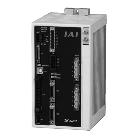
IAI ssel User manual

Operation Manual
First Edition
SSEL Controlle
r

CAUTION
Operator Alarm on Low Battery Voltage
This controller can be equipped with the following optional backup batteries for retention of data in the
event of power failure:
[1] System-memory backup battery (Optional)
For retention of position data, global variables/flags, error list, strings, etc.
[2] Absolute-data backup battery (absolute encoder specification)
For retention of encoder rotation data.
Since these batteries are not rechargeable, they will be eventually consumed. Unless the batteries are
replaced in a timely manner, the voltage will drop to a level where the data can no longer be retained. If a
power failure occurs in this condition, the data will be lost. (The life of each battery varies depending on
the operating time.)
Once the data is lost, the controller will not operate normally the next time the power is turned on, and
recovery will take time.
To prevent this problem, this controller can output a low battery voltage alarm from its I/O port.
You can specify a desired output port to issue a voltage-low warning for the system-memory backup
battery.
Set “15” as the input function specification value in the I/O parameter corresponding to the output port
number you want to specify.
Setting example)
To specify output port No. 306 to issue a voltage-low warning for the system-memory backup battery,
set “15” in I/O parameter No. 52.
You can specify a desired output port to issue a voltage-low warning for the absolute-data backup
battery.
Set “16” as the input function specification value in the I/O parameter corresponding to the output port
number you want to specify.
Setting example)
To specify output port No. 307 to issue a voltage-low warning for the absolute-data backup battery, set
“16” in I/O parameter No. 53.
It is recommended that this function be utilized to prevent unnecessary problems resulting from low
battery voltage (consumption of battery life).
In particular, the person in charge of system design should utilize this function to provide a design means
for issuing an operator alarm using an output signal from an I/O port, while the person in charge of
electrical design should provide an electrical means for achieving the same effect.
For the battery replacement procedure, refer to the applicable section in the operating manual.
It is recommended that you always backup the latest data to a PC in case of voltage drop in the system-
memory battery or unexpected controller failure.

CAUTION
Optional System-Memory Backup Battery
The SSEL controller can be used with the optional system-memory backup battery.
Caution: When installing the system-memory backup battery, “Other parameter No. 20” must be set to
“2.”
Installing the system-memory backup battery will add the following functions to the controller:
•Save SEL global data
Data of global variables, flags and strings will be retained even after the main power is turned off.
•Save RAM position data
Position data changed by SEL programs will be retained even after the main power is turned off.
•Save an error list
An error list containing up to 50 most recent errors will be retained even after the main power is
turned off.
If you need any or all of the above functions, you must install the optional system-memory backup battery.

Safety Precautions
Please read the information in “Safety Precautions” carefully before selecting a model and using the
product.
The precautions described below are designed to help you use the product safely and avoid bodily injury
and/or property damage.
Directions are classified as “danger,” “warning,” “caution” and “note,” according to the degree of
risk.
Danger Failure to observe the instruction will result in an imminent danger leading to
death or serious injury.
Warning Failure to observe the instruction may result in death or serious injury.
Caution Failure to observe the instruction may result in injury or property damage.
Note The user should take heed of this information to ensure the proper use of the
product, although failure to do so will not result in injury.
This product has been designed and manufactured as a component for use in general industrial
machinery.
Devices must be selected and handled by a system designer, personnel in charge of the actual operation
using the product or similar individual with sufficient knowledge and experience, who has read both the
catalog and operation manual (particularly the “Safety Precautions” section). Mishandling of the product
poses a risk.
Please read the operation manuals for all devices, including the main unit and controller.
It is the user’s responsibility to verify and determine the compatibility of this product with the user’s
system, and to use them properly.
After reading the catalog, operation manual and other materials, be sure to keep them in a convenient
place easily accessible to the personnel using this product.
When transferring or loaning this product to a third party, be sure to attach the catalog, operation manual
and other materials in a conspicuous location on the product, so that the new owner or user can
understand its safe and proper use.
The danger, warning and caution directions in this “Safety Precautions” do not cover every possible case.
Please read the catalog and operation manual for the given device, particularly for descriptions unique to
it, to ensure its safe and proper handling.
Danger
[General]
zDo not use this product for the following applications:
1. Medical equipment used to maintain, control or otherwise affect human life or physical health
2. Mechanisms and machinery designed for the purpose of moving or transporting people
3. Important safety parts of machinery
This product has not been planned or designed for applications requiring high levels of safety. Use of
this product in such applications may jeopardize the safety of human life. The warranty covers only the
product as it is delivered.

[Installation]
zDo not use this product in a place exposed to ignitable, inflammable or explosive substances. The
product may ignite, burn or explode.
zAvoid using the product in a place where the main unit or controller may come in contact with water or
oil droplets.
zNever cut and/or reconnect the cables supplied with the product for the purpose of extending or
shortening the cable length. Doing so may result in fire.
[Operation]
zIf you are using a pace maker or other mechanical implant, do not come within one meter of the
product. The strong magnetic field generated by the product may cause the pace maker, etc., to
malfunction.
zDo not pour water onto the product. Spraying water over the product, washing it with water or using it
in water may cause the product to malfunction, resulting in injury, electric shock, fire, etc.
[Maintenance, Inspection, Repair]
zNever modify the product. Unauthorized modification may cause the product to malfunction, resulting in
injury, electric shock, fire, etc.
zDo not disassemble and reassemble the components relating to the basic structure of the product or its
performance and function. Doing so may result in injury, electric shock, fire, etc.
Warning
[General]
zDo not use the product outside the specifications. Using the product outside the specifications may
cause it to fail, stop functioning or sustain damage. It may also significantly reduce the service life of
the product. In particular, observe the maximum loading capacity and speed.
[Installation]
zIf the machine will stop in the case of system problem such as emergency stop or power failure, design
a safety circuit or other device that will prevent equipment damage or injury.
zBe sure to provide Class D grounding for the controller and actuator (formerly Class 3 grounding:
Grounding resistance at 100 Ωor less). Leakage current may cause electric shock or malfunction.
zBefore supplying power to and operating the product, always check the operation area of the
equipment to ensure safety. Supplying power to the product carelessly may cause electric shock or
injury due to contact with the moving parts.
zWire the product correctly by referring to the operation manual. Securely connect the cables and
connectors so that they will not be disconnected or come loose. Failure to do so may cause the
product to malfunction or cause fire.
[Operation]
zDo not touch the terminal block or various switches while the power is supplied to the product. Failure
to observe this instruction may result in electric shock or malfunction.
zBefore operating the moving parts of the product by hand (for the purpose of manual positioning, etc.),
confirm that the servo is turned off (using the teaching pendant). Failure to observe this instruction may
result in injury.
zThe cables supplied with the product are flexible, but they are not robot cables. Do not store the cables
in a movable cable duct (cable bearer, etc.) that bends more than the specified bending radius.
zDo not scratch the cables. Scratching, forcibly bending, pulling, winding, crushing with heavy object or
pinching a cable may cause it to leak current or lose continuity, resulting in fire, electric shock,
malfunction, etc.

zTurn off the power to the product in the event of power failure. Failure to do so may cause the product
to suddenly start moving when the power is restored, thus resulting in injury or product damage.
zIf the product is generating heat, smoke or a strange smell, turn off the power immediately. Continuing
to use the product may result in product damage or fire.
zIf any of the internal protective devices (alarms) of the product has actuated, turn off the power
immediately. Continuing to use the product may result in product damage or injury due to malfunction.
Once the power supply is cut off, investigate and remove the cause and then turn on the power again.
zIf the LEDs on the product do not illuminate after turning on the power, turn off the power immediately.
The protective device (fuse, etc.) on the live side may remain active. Request repair to the IAI sales
office from which you purchased the product.
[Maintenance, Inspection, Repair]
zBefore conducting maintenance/inspection, parts replacement or other operations on the product,
completely shut down the power supply. At this time, take the following measures:
1. Display a sign that reads, “WORK IN PROGRESS. DO NOT TURN ON POWER” at a conspicuous
place, in order to prevent a person other than the operator from accidentally turning on the power
while the operation is working.
2. When two or more operators are to perform maintenance/inspection together, always call out every
time the power is turned on/off or an axis is moved in order to ensure safety.
[Disposal]
zDo not throw the product into fire. The product may burst or generate toxic gases.
Caution
[Installation]
zDo not use the product under direct sunlight (UV ray), in a place exposed to dust, salt or iron powder,
in a humid place, or in an atmosphere of organic solvent, phosphate-ester machine oil, sulfur dioxide
gas, chlorine gas, acids, etc. The product may lose its function over a short period of time, or exhibit a
sudden drop in performance or its service life may be significantly reduced.
zDo not use the product in an atmosphere of corrosive gases (sulfuric acid or hydrochloric acid),
inflammable gases or ignitable liquids. Rust may form and reduce the structural strength or the motor
may ignite or explode.
zWhen using the product in any of the places specified below, provide a sufficient shield. Failure to do
so may result in malfunction:
1. Place where large current or high magnetic field is present
2. Place where welding or other operations are performed that cause arc discharge
3. Place subject to electrostatic noise
4. Place with potential exposure to radiation
zInstall the main unit and controller in a place subject to as little dust as possible. Installing them in a
dusty place may result in malfunction.
zDo not install the product in a place subject to large vibration or impact (4.9 m/s2 or more). Doing so
may result in the malfunctioning of the product.
zProvide an emergency-stop device in a readily accessible position so the device can be actuated
immediately upon occurrence of a dangerous situation during operation. Lack of such device in an
appropriate position may result in injury.
zProvide sufficient maintenance space when installing the product. Routine inspection and maintenance
cannot be performed without sufficient space, which will eventually cause the equipment to stop or the
product to sustain damage.
zDo not hold the moving parts of the product or its cables during installation. It may result in injury.
zAlways use IAI’s genuine cables for connection between the controller and the actuator. Also use IAI’s
genuine products for the key component units such as the actuator, controller and teaching pendant.
zBefore installing or adjusting the product or performing other operations on the product, display a sign
that reads, “WORK IN PROGRESS. DO NOT TURN ON POWER.” If the power is turned on
inadvertently, injury may result due to electric shock or sudden activation of an actuator.
[Operation]
zTurn on the power to individual equipment one by one, starting from the equipment at the highest level
in the system hierarchy. Failure to do so may cause the product to start suddenly, resulting in injury or
product damage.
zDo not insert a finger or object in the openings in the product. It may cause fire, electric shock or injury.
zDo not bring a floppy disk or other magnetic media within one meter of the product. The magnetic field
generated by the magnet may destroy the data in the floppy disk, etc.
[Maintenance, Inspection, Repair]
zWhen the power was turned off and the cover was opened to replace the battery, etc., do not touch the
condenser terminal in the product immediately after the power was turned off (within 30 seconds).
Residual voltage may cause electric shock.
zDo not touch the terminals when performing an insulation resistance test. Electric shock may result.
(Do not perform any withstand voltage test, since the product uses DC voltage.)
Note
[General]
zIf you are planning to use the product under a condition or environment not specified in the catalogs
and operation manual, or in an application requiring strict safety such as aircraft facility, combustion
system, entertainment machine, safety device or other equipment having significant impact on human
life or property, design operating ranges with sufficient margins from the ratings and design
specifications or provide sufficient safety measures such as fail-safes. Whatever you do, always
consult IAI’s sales representative.
[Installation]
zDo not place objects around the controller that will block airflows. Insufficient ventilation may damage
the controller.
zDo not configure a control circuit that will cause the load to drop in case of power failure. Configure a
control circuit that will prevent the table or load from dropping when the power to the machine is cut off
or an emergency stop is actuated.
[Installation, Operation, Maintenance]
zWhen handling the product, wear protective gloves, protective goggles, safety shoes or other
necessary gear to ensure safety.
[Disposal]
zWhen the product becomes no longer usable or necessary, dispose of it properly as an industrial
waste.
Others
IAI shall not be liable whatsoever for any loss or damage arising from a failure to observe the
items specified in “Safety Precautions.”
If you have any question regarding the product, contact the IAI sales office near you. The
addresses and phone numbers of our sales offices are listed at the end of the catalog.

Table of Contents
Table of Contents
Part 1 Installation......................................................................................1
Chapter 1 Overview...................................................................................................................1
1. Introduction.................................................................................................................................. 1
2. Type............................................................................................................................................. 1
3. SSEL Controller Functions .......................................................................................................... 2
4. System Setup .............................................................................................................................. 4
5. Warranty Period and Scope of Warranty..................................................................................... 5
Chapter 2 Specifications............................................................................................................6
1. Controller Specifications.............................................................................................................. 6
2. Name and Function of Each Part................................................................................................ 7
Chapter 3 Installation and Wiring.............................................................................................23
1. External Dimensions.................................................................................................................. 23
2. Installation Environment............................................................................................................ 26
3. Heat Radiation and Installation.................................................................................................. 27
4. Noise Control Measures and Grounding................................................................................... 28
5. Power-Supply Capacity and Heat Output.................................................................................. 31
6. Auxiliary Power Equipment........................................................................................................ 33
6.1 Example of Auxiliary Power Equipment Configuration.................................................... 33
7. Wiring......................................................................................................................................... 34
7.1 Connecting the Power Cables......................................................................................... 34
7.2 Connecting the Actuator.................................................................................................. 35
7.3 Connecting the Emergency Stop Input, Enable Input and Brake Power Input ............... 36
7.4 Connecting the PIO Cable (I/O)...................................................................................... 39
7.5 External I/O Specifications.............................................................................................. 44
7.6 Connecting Regenerative Resistance Units (RB)........................................................... 48
7.7 Connecting the Teaching Pendant/PC Software (TP) (Optional).................................... 50
7.8 Connecting the Panel Unit (Optional).............................................................................. 50
7.9 Installing the Absolute-Data Backup Battery (Optional).................................................. 56
7.10 Installing the System-memory Backup Battery (Optional) .............................................. 57
Chapter 4 Operation................................................................................................................ 58
1. Startup ....................................................................................................................................... 58
1.1 Power ON Sequence....................................................................................................... 59
1.2 Power Cutoff Sequence .................................................................................................. 59

Table of Contents
2. How to Perform Absolute Reset (Absolute Specification) ......................................................... 60
2.1 Preparation...................................................................................................................... 60
2.2 Procedure........................................................................................................................ 60
3. How to Start a Program............................................................................................................. 65
3.1 Starting a Program byAuto-Start via Parameter Setting................................................. 66
3.2 Starting via External Signal Selection ............................................................................. 67
4. Drive-Source Recovery Request and Operation-Pause Reset Request .................................. 69
5. Controller Data Structure........................................................................................................... 70
5.1 How to Save Data ........................................................................................................... 71
5.2 Points to Note.................................................................................................................. 73
Chapter 5 Maintenance ...........................................................................................................74
1. Inspection points........................................................................................................................ 74
2. Spare consumable parts............................................................................................................ 74
3. Replacement Procedure for System-Memory Backup Battery (Optional)................................. 75
4. Replacement Procedure for Absolute-Data Backup Battery (Optional) .................................... 77
Part 2 Programs.....................................................................................79
Chapter 1 SEL Language Data................................................................................................79
1. Values and Symbols Used in SEL Language............................................................................ 79
1.1 List of Values and Symbols Used.................................................................................... 79
1.2 I/O Ports .......................................................................................................................... 80
1.3 Virtual I/O Ports............................................................................................................... 81
1.4 Flags................................................................................................................................ 83
1.5 Variables.......................................................................................................................... 84
1.6 Tags................................................................................................................................. 87
1.7 Subroutines..................................................................................................................... 88
1.8 Symbols........................................................................................................................... 89
1.9 Character-String Literals ................................................................................................. 89
1.10 Axis Specification ............................................................................................................ 90
2. Position Part .............................................................................................................................. 92
3. Command Part .......................................................................................................................... 93
3.1 SEL language Structure .................................................................................................. 93
3.2 Extension Condition ........................................................................................................ 94

Table of Contents
Chapter 2 List of SEL Language Command Codes.................................................................95
1. By Function................................................................................................................................ 95
2. Alphabetical Order................................................................................................................... 100
Chapter 3 Explanation of Commands.................................................................................... 105
1. Commands .............................................................................................................................. 105
1.1 Variable Assignment...................................................................................................... 105
1.2 Arithmetic Operation...................................................................................................... 108
1.3 Function Operation.........................................................................................................111
1.4 Logical Operation...........................................................................................................114
1.5 Comparison Operation...................................................................................................117
1.6 Timer ..............................................................................................................................118
1.7 I/O, Flag Operation........................................................................................................ 121
1.8 Program Control............................................................................................................ 132
1.9 Task Management......................................................................................................... 135
1.10 Position Operation......................................................................................................... 140
1.11 Actuator Control Declaration......................................................................................... 155
1.12 Actuator Control Command........................................................................................... 171
1.13 Structural IF................................................................................................................... 194
1.14 Structural DO................................................................................................................. 197
1.15 Multi-Branching ............................................................................................................. 199
1.16 System Information Acquisition..................................................................................... 203
1.17 Zone .............................................................................................................................. 206
1.18 Communication ............................................................................................................. 210
1.19 String Operation ............................................................................................................ 217
1.20 Arch-Motion-Related ..................................................................................................... 226
1.21 Palletizing-Related ........................................................................................................ 231
1.22 Palletizing Calculation Command ................................................................................. 238
1.23 Palletizing Movement Command .................................................................................. 241
1.24 Building of Pseudo-Ladder Task ................................................................................... 243
1.25 Extended Command...................................................................................................... 245
Chapter 4
Key Characteristics of Actuator Control Commands and Points to Note .............. 248
1. Continuous Movement Commands......................................................................................... 248
2. PATH/PSPL Commands.......................................................................................................... 250
3. CIR/ARC Commands .............................................................................................................. 250
4. CIR2/ARC2/ARCD/ARCC Commands.................................................................................... 250

Table of Contents
Chapter 5 Palletizing Function (2-axis Specification).............................................................251
1. How to Use.............................................................................................................................. 251
2. Palletizing Setting.................................................................................................................... 251
3. Palletizing Calculation ............................................................................................................. 256
4. Palletizing Movement .............................................................................................................. 257
5. Program Examples.................................................................................................................. 258
Chapter 6 Pseudo-Ladder Task.............................................................................................260
1. Basic Frame............................................................................................................................. 260
2. Ladder Statement Field ........................................................................................................... 261
3. Points to Note.......................................................................................................................... 261
4. Program Example.................................................................................................................... 262
Chapter 7 Application Program Examples.............................................................................263
1. Operation by Jog Command [Doll-Picking Game Machine].................................................... 263
2. Operation by Point Movement Command [Riveting System].................................................. 266
Chapter 8 Real-Time Multi-Tasking........................................................................................269
1. SEL Language......................................................................................................................... 269
2. Multi-Tasking............................................................................................................................ 270
3. Difference from a Sequencer................................................................................................... 271
4. Release of Emergency Stop.................................................................................................... 272
5. Program Switching .................................................................................................................. 273
Chapter 9 Example of Building a System..............................................................................274
1. Equipment................................................................................................................................ 274
2. Operation................................................................................................................................. 274
3. Overview of the Screw-Tightening System.............................................................................. 275
4. Hardware................................................................................................................................. 276
5. Software................................................................................................................................... 277
Chapter 10 Example of Building a System..............................................................................279
1. Position Table .......................................................................................................................... 279
2. Programming Format............................................................................................................... 280
3. Positioning to Five Positions.................................................................................................... 281
4. How to Use TAG and GOTO ................................................................................................... 282
5. Moving Back and Forth between Two Points.......................................................................... 283
6. Path Operation ........................................................................................................................ 284
7. Output Control during Path Movement.................................................................................... 285
8. Circle/Arc Operation................................................................................................................ 286

Table of Contents
9. Home Return Completion Output............................................................................................ 287
10. Axis Movement by Input Waiting and Completion Output....................................................... 288
11. Changing the Moving Speed ................................................................................................... 289
12. Changing the Speed during Operation.................................................................................... 290
13. Local/Global Variables and Flags............................................................................................ 291
14. How to Use Subroutines.......................................................................................................... 292
15. Pausing the Operation............................................................................................................. 293
16. Canceling the Operation 1 (CANC)......................................................................................... 294
17. Canceling the Operation 2 (STOP).......................................................................................... 295
18. Movement by Position Number Specification.......................................................................... 296
19. Movement by External Position Data Input............................................................................. 297
20. Conditional Jump..................................................................................................................... 298
21. Waiting Multiple Inputs............................................................................................................. 299
22. How to Use Offset ................................................................................................................... 300
23. Executing an Operation N times.............................................................................................. 301
24. Constant-pitch Feed................................................................................................................ 302
25. Jogging.................................................................................................................................... 303
26. Switching Programs................................................................................................................. 304
27. Aborting a Program ................................................................................................................. 305
Part 3 Positioner Mode.........................................................................306
Chapter 1 Modes and SignalAssignments............................................................................306
1. Feature of Each Mode............................................................................................................. 306
2. Number of Positions Supported in Each Mode ....................................................................... 307
3. Quick Mode Function Reference Table ................................................................................... 307
4. Interface List of All PIO Patterns ............................................................................................. 308
Chapter 2 Standard Mode......................................................................................................309
1. I/O Interface List...................................................................................................................... 309
2. Parameters.............................................................................................................................. 310
3. Details of Each Input Signal .................................................................................................... 310
4. Details of Each Output Signal.................................................................................................. 313
5. Timing Chart............................................................................................................................ 314
5.1 Recognition of I/O Signals............................................................................................. 314
5.2 Home Return................................................................................................................. 315
5.3 Movements through Positions....................................................................................... 316

Table of Contents
Chapter 3 Product Switching Mode.......................................................................................318
1. I/O Interface List...................................................................................................................... 318
2. Parameters.............................................................................................................................. 319
3. Details of Each Input Signal .................................................................................................... 320
4. Details of Each Output Signal.................................................................................................. 323
5. Timing Chart............................................................................................................................ 324
5.1 Recognition of I/O Signals............................................................................................. 324
5.2 Home Return................................................................................................................. 325
5.3 Movements through Positions....................................................................................... 326
Chapter 4 2-axis Independent Mode .....................................................................................328
1. I/O Interface List...................................................................................................................... 328
2. Parameters.............................................................................................................................. 329
3. Details of Each Input Signal .................................................................................................... 330
4. Details of Each Output Signal.................................................................................................. 332
5. Timing Chart............................................................................................................................ 333
5.1 Recognition of I/O Signals............................................................................................. 333
5.2 Home Return................................................................................................................. 334
5.3 Movements through Positions....................................................................................... 335
Chapter 5 Teaching Mode......................................................................................................337
1. I/O Interface List...................................................................................................................... 338
2. Parameters.............................................................................................................................. 339
3. Details of Each Input Signal .................................................................................................... 339
4. Details of Each Output Signal.................................................................................................. 342
5. Timing Chart............................................................................................................................ 344
5.1 Recognition of I/O Signals............................................................................................. 344
5.2 Home Return................................................................................................................. 345
5.3 Movements through Positions....................................................................................... 346
5.4 Timings in the Teaching Mode....................................................................................... 347
Chapter 6 DS-S-C1 Compatible Mode .................................................................................. 348
1. I/O Interface List...................................................................................................................... 348
2. Parameters.............................................................................................................................. 349
3. Details of Each Input Signal .................................................................................................... 349
4. Details of Each Output Signal.................................................................................................. 351
5. Timing Chart............................................................................................................................ 352
5.1 Recognition of I/O Signals............................................................................................. 352
5.2 Home Return................................................................................................................. 353
5.3 Movements through Positions....................................................................................... 354

Table of Contents
* Appendix................................................................................................355
Actuator Specification List.........................................................................................................355
Battery Backup Function...........................................................................................................359
1. System-Memory Backup Battery............................................................................................. 359
2. Absolute-Data Backup Battery for Absolute Encoder.............................................................. 361
Synchro Function ......................................................................................................................363
1. Common Items (Applicable to Both theAbsolute Specification and Incremental Specification)
................................................................................................................................................. 363
2. Incremental Specification......................................................................................................... 363
3. Absolute Specification (When Both the Master Axis and Slave Axis are of Absolute
Specification)........................................................................................................................... 363
Absolute Reset for Synchro Specification .................................................................................364
1. Synchro Axes........................................................................................................................... 364
2. Position Alignment of Synchro-Axis Sliders............................................................................. 365
3. Special Absolute Reset Procedure.......................................................................................... 365
4. Standard Absolute Reset Procedure....................................................................................... 368
5. Notes on Use of Synchro Function.......................................................................................... 369
Parameter Utilization.................................................................................................................370
1. Utilization Examples of I/O Parameters................................................................................... 371
2. Utilization Examples of Axis-specific Parameters.................................................................... 378
3. Parameter Utilization Examples (Reference).......................................................................... 389
List of Parameters.....................................................................................................................393
1. I/O Parameters........................................................................................................................ 394
2. Parameters Common to All Axes............................................................................................. 402
3. Axis-Specific Parameters......................................................................................................... 404
4. Driver Parameters ................................................................................................................... 408
5. Encoder Parameters.................................................................................................................411
6. I/O Devices.............................................................................................................................. 412
7. Other Parameters.................................................................................................................... 413
8. Manual Operation Types ......................................................................................................... 418
Combination Table of PSEL Linear/Rotary Control Parameters................................................ 419
Error Level Control....................................................................................................................420
Error List ..............................................................................................................................422
Troubleshooting of SSEL Controller..........................................................................................458
Trouble Report Sheet
.............................................................................................................463

1
Part 1 Installation
Part 1 Installation
Chapter 1 Overview
1. Introduction
Thank you for purchasing the SSEL Controller.
Please read this manual carefully, and handle the product with due care and operate it correctly.
Keep this manual in a safe place and reference relevant items when needed.
When actually starting up your system or if you have encountered a problem, you should also refer to the
manuals for the teaching pendant, PC software and other components used with the system, in addition to
this manual.
This manual does not cover all possible operations other than normal operations, or unexpected events
such as complex signal changes resulting from use of critical timings.
Accordingly, you should consider items not specifically explained in this manual as “prohibited.”
* Utmost effort has been made to ensure accuracy and completeness of the information contained in this
manual. However, should you find any error in the manual or if you have any comment regarding its
content, please contact IAI.
Keep this manual in a convenient place so that you can quickly reference it whenever necessary.
2. Type
Refer to the following table for details on type specification.
Example of type specification
Type specification table
Series Controller
type Number
of axes
Details of axis 1 to axis 2
Motor
output (W) Encoder
type Brake Standard
I/O
I/O flat cable
length Power-
source
voltage
1: Single-
phase
100 V
2: Single-
phase
200 V
C
(Standard
specification)
1
(Axis 1)
2
(Axis 2)
I
(Incremental)
A
(Absolute)
Blank
(Without
brake)
B
(With brake)
NP
Standard PIO
24 inputs/8
outputs
NPN
specification
PN
Standard PIO
24 inputs/8
outputs
PNP
specification
2: 2 m
(Standard)
3: 3 m
5: 5 m
0: None
(30W for RS)
Blank
(Without
creep)
C
(With creep)
Blank
(Without
home sensor)
I
(With home
sensor)
Blank
(No synchro
axis)
M
(Master axis
specification)
S
(Slave axis
specification)
Creep Home
senso
r
Synchro
specification

2
Part 1 Installation
3. SSEL Controller Functions
The functions provided by the SSEL controller are structured in the following manner.
The SSEL controller has the “program mode” in which SEL programs are input to operate the actuator(s),
and the “positioner mode” in which position numbers are specified from the host PLC to operate the
actuator(s).
The positioner mode provides five sub-modes to meet the needs of various applications.
The program mode has been selected at the factory prior to the shipment of the controller (Other
parameter No. 25 = 0).
Caution: Two modes cannot be selected at the same time.
Program mode
Positioner mode
Standard mode
Product switching mode
2-axis independent mode
Teaching mode
DS-S-C1 compatible mode
SSEL

3
Part 1 Installation
This controller can be configured with one axis and two axes. Just like other conventional SEL controllers,
this controller can be combined with various actuators. When connecting an actuator, be sure to use a
dedicated cable.
•Turn on the I/O power and brake power (for the specification with brake) before or simultaneously with
the main power (control power + motor power).
•Take the control power and motor power from the same power supply and turn on both powers
simultaneously.
•Before performing a check or inserting/removing a connector, turn off the power and wait for at least 10
minutes. Even after the power is turned off, the internal circuits will continue to carry high voltages for a
short period.
•About actuator duty
IAI recommends that our actuators be used at a duty of 50% or less as a guideline in view of the
relationship of service life and accuracy:
Duty (%) = InactivitytimeMotion TimeonDecelerati/onAccelerati
+X 100
•After turning off the control power, be sure to wait for at least 5 seconds before turning it back on.
If the control power is turned on within 5 seconds, “E88, Power error (Other)” may generate.
•Do not insert or remove connectors while the controller power is on. Doing so may cause malfunction.
•Note on introducing a controller of absolute specification
The following steps must be taken to initialize the absolute-data backup battery circuit to prevent the
battery from being consumed quickly. Perform the initialization by following these steps:
[1] Before connecting the encoder cable, disconnect the absolute-data backup battery connector.
[2] Connect the encoder cable.
[3] Turn on the main power.
[4] Connect the absolute-data backup battery.
The above steps must always be performed after the encoder cable has been disconnected for any
reason, such as to move the controller.
Read the operation manual for each actuator. If you have purchased our optional PC software and/or
teaching pendant, read the respective operation manuals, as well.
* Utmost effort has been made to ensure that the information contained in this manual is true and
correct. However, should you find any error or if you have any comment regarding the content,
please contact IAI.

4
Part 1 Installation
4. System Setup
* Note on connecting the encoder cable to a controller of absolute specification
Follow the steps below when connecting the encoder cable to a controller of absolute specification. If
the specified steps are not followed, the absolute-data backup battery may be consumed quickly.
[1] Before connecting the encoder cable, disconnect the absolute-data backup battery connector.
[2] Connect the encoder cable, and turn on the main power.
[3] Connect the absolute-data backup battery connector. Once the connector has been plugged in,
the main power can be turned off.
For the installation of the absolute-data backup battery, refer to 7.9, “Installing the Absolute-Data
Backup Battery” in Chapter 3.
If you have disconnected the encoder cable for any reason, such as to move the controller, also follow
the same steps to connect the absolute-data backup battery connector.
Host system
Conversion cable
Teaching
pendant
Emergency
stop switch
Panel unit
Enable
switch Auxiliary power
equipment
Regenerative
resistance unit
Grounded
24-VDC brake
power supply
Absolute-data
backup batteries
Axis 1
Axis 2

5
Part 1 Installation
5. Warranty Period and Scope of Warranty
The SSEL Controller you have purchased passed our strict outgoing inspection. This unit is covered by
the following warranty:
1. Warranty Period
The warranty period shall be either of the following periods, whichever ends first:
•18 months after shipment from our factory
•12 months after delivery to a specified location
2. Scope of Warranty
Should the product fail during the above period under a proper use condition due to a fault on the part
of the manufacturer, IAI will repair the defect free of charge. However, the following cases are
excluded from the scope of warranty:
•Discoloration of paint or other normal aging
•Wear of consumable parts due to use
•Subjective imperfection, such as noise not affecting mechanical function
•Defect caused by inappropriate handling or use by the user
•Defect caused by inappropriate or erroneous maintenance/inspection
•Defect caused by use of a part other than IAI’s genuine part
•Defect caused by unauthorized modification, etc., not approved by IAI or its agent
•Defect due to an act of God, accident, fire, etc.
The warranty covers only the product as it is delivered. IAI shall not be liable for any loss arising in
connection with the delivered product. The user must bring the defective product to our factory to
receive a warranty repair.
3. Scope of Service
The price of the delivered product does not include costs incurred in association with program
generation, dispatch of technician, etc. Therefore, a separate fee will be chargeable in the following
cases even during the warranty period:
•Guidance on installation/adjustment and witnessing of test operation
•Maintenance/inspection
•Technical guidance and training on operation, wiring method, etc.
•Technical guidance and training regarding programs, such as program generation
•Other services and operations where IAI finds a need to charge a separate fee

6
Part 1 Installation
Chapter 2 Specifications
1. Controller Specifications
Base specifications of this product
100-V input specification 200-V input specification
Total output when maximum
number of axes are connected 400 W 800 W
Control power input Single-phase 100 to 115 VAC ±
10% Single-phase 200 to 230 VAC ±
10%
Motor power input Single-phase 100 to 115 VAC ±
10% Single-phase 200 to 230 VAC ±
10%
Power-supply frequency 50/60 Hz ±5%
Resistance against momentary
power failure 0.5 cycle (Not dependent on phase)
Withstand voltage 1500 VAC for 1 minute *1
Insulation resistance 500 VDC, 100 MΩor more
Leak current Controller alone (no actuator connected): 1.0 mA max.
Drive-source cutoff method Internal relay
Emergency stop input Contact B input (Internal power-supply type)
Emergency stop action Deceleration stop + Regenerative brake by timer
Enable input Contact B input (Internal power-supply type)
Control method AC full digital servo
Position detection method Incremental serial encoder
Absolute serial encoder
ABZ (UVW) parallel encoder
Battery Absolute-data backup battery/system-memory backup battery (Optional)
Lithium battery: AB-5 by IAI, 3.6 V/2000 mAh
Programming language Super SEL language
Number of program steps 2000 steps (total)
Number of positions 1500 positions (total)
Number of programs 64 programs
Multi-tasking capability 8 programs
Storage device Flash ROM
Data input method Teaching pendant or PC software
Electromagnetic brake power 24 VDC ±10%
2 A peak (1 A peak/axis)
Electromagnetic brake output
voltage 45 VDC (90 V at over-excitation)
PIO power input 24 VDC ±10%
Safety category Category B (Built-in relay)
* Safety category 1 can be met by connecting an external safety relay,
etc.
Regenerative resistor 20 W, built-in (External resistance unit(s) can be connected.)
PIO inputs 24 points, NPN or PNP (Selectable as factory setting)
PIO outputs 8 points, NPN or PNP (Selectable as factory setting)
Air cooling method Forced air-cooling
Weight 1380 g
External dimensions 100 (W) x 195 (H) x 126 (D); mounting pitch 186 mm
202.6 (H) if the absolute-data backup battery holder is installed.
Accessories
I/O flat cable
Power connector
EMG connector
ENB/BK connector
*1) The withstand voltage of the motor used in each actuator is 1,000 VAC for 1 minute. If withstand voltage test is performed with
the controller connected to an actuator, ensure that voltage exceeding 1,000 VAC will not be applied for more than 1 minute.
Other manuals for ssel
3
Table of contents
Other IAI Controllers manuals

IAI
IAI ROBO Cylinder RCS4- SA4C User manual

IAI
IAI PCON-C User manual

IAI
IAI X-SEL User manual

IAI
IAI ROBO Cylinder RCP2 Series User manual

IAI
IAI ERC2 Installation manual

IAI
IAI Rcon User manual

IAI
IAI ISDB Series User manual

IAI
IAI ROBO Cylinder RCS2 User manual

IAI
IAI X-SEL-J*-1-CC0 series User manual

IAI
IAI SCON-CA User manual
Popular Controllers manuals by other brands

resideo
resideo R7284 Series Quick reference guide

Toyama
Toyama SmartGen HGM400N Series owner's manual

RKC INSTRUMENT
RKC INSTRUMENT CD101 instruction manual

Celerity
Celerity ACX3200 Series user guide

Kelly
Kelly KLS-RM Series user manual

Bosch
Bosch Rexroth IndraDrive CsDrive System with HCS01 instruction manual