VOX electronics CGL650IX User manual

CGL650IX / CGL950IX
OPERATING INSTRUCTIONS
COOKER HOOD
UPUTSTVO ZA UPOTREBU
ASPIRATOR
NAVODILA ZA UPORABO KUHINJSKA NAPA
UPUTE ZA UPORABU
KUHINJSKA NAPA
MANUAL DE ISTRUÇÕES EXAUSTOR
GBR
SVN
HRV
PRT

CGL650IX / CGL950IX
OPERATING INSTRUCTIONS COOKER HOOD
GBR

1
Read the User Manual Carefully!
MODEL: CGL650IX
MODEL: CGL950IX

2
“Complies with EEE Regulation. No PCB Included”
1 TECHNICAL DRAWING 4
2 WARNINGS AND SAFETY PRECAUTIONS 5
2.1 Life-Threatening Danger, Poisoning Danger 7
2.2 Danger of electric shock! 7
2.3 Danger of physical injury! 7
2.4 Danger of burn, danger of electric shock! 8
2.5 Dangers of re and physical injury! 8
3 USAGES WITH AND WITHOUT CARBON FILTER 9
3.1 Replacement of Carbon Filter 10
3.2 Replacement of Carbon Filter 10
4 CLEANING AND PREVENTIVE MAINTENANCE 11
4.1 Washing in Dishwasher 11
4.2 Hand Wash 11
4.3 Removal/Installation of Aluminium Filter 11
5 INSTALLATION OF APPLIANCE 12
5.1 Installation and Unpacking of the Appliance 12
5.2 Installation and Unpacking of the Appliance 12
5.3 Exhaust Air Mode 13
5.4 Air Discharge Line 13
5.5 Checking the Wall 13
5.6 Electrical Connection 13
5.7 Danger of Electric Shock! 13
6 CONTENT OF PACKAGE 14
7 OVERVIEW OF COOKER HOOD 15
8 ASSEMBLY OF PRODUCT 16
8.1 Installation Diagram and Components 16
8.2 Assembly of Plastic Flue 17
9 ASSEMBLY OF PLATE FUELS 18
10 USE OF PRODUCT 19
10.1 On Glass 3 Spd Touch Button 19
10.2 Push Button 19
11 REPLACEMENT OF LAMPS 20
11.1 Replacement of Halogen Lamp 20
11.2 Replacement of Spark Plug Lamp 20
12 AUTHORIZED TECHNICAL SERVICE 21
12.1 Potential Failures and Solutions 22
12.2 Technical Table 22

3
1 TECHNICAL DRAWING
Fig. 1: TECHNICAL DRAWING

4
2 WARNINGS AND SAFETY PRECAUTIONS
■This appliance can be used by children
aged from 8 years and above and persons with
reduced physical, sensory or mental capabili-
ties or lack of experience and knowledge if they
have been given supervision or instruction con-
cerning use of the appliance in a safe way and
understand the hazards involved.
■This product is designed for home use.
■Usage voltage of your product is 220-240
Volt~50 Hz.
■ Power cord of your product is tted with a
grounded plug. That cable must denitely be
connected to a grounded socket.
■The whole electrical wiring must be installed
by a qualied electrician.
■Installation by unauthorized persons could
lead to poor operation performance, damage to
the product, and accidents.
■Feeder cable of the appliance mustn’t be
exposed to jamming or crashing during as-
sembly. Feeder cable mustn’t be placed near
the cooker. In such cases, it might melt down
and lead to re.
■Do not plug in the appliance before the ins-
tallation.
■Make sure that the installation place allows
the user to easily unplug the power cable in
case of any danger.
■Do not touch your product’s lamps when
they work for a long time. Since they would be
hot, they could burn your hand.
■Kitchen cooker hoods are designed for nor-
mal cooking and home use. For uses other than
specied, there is the risk of failure and the app-
liance becomes out of warranty.
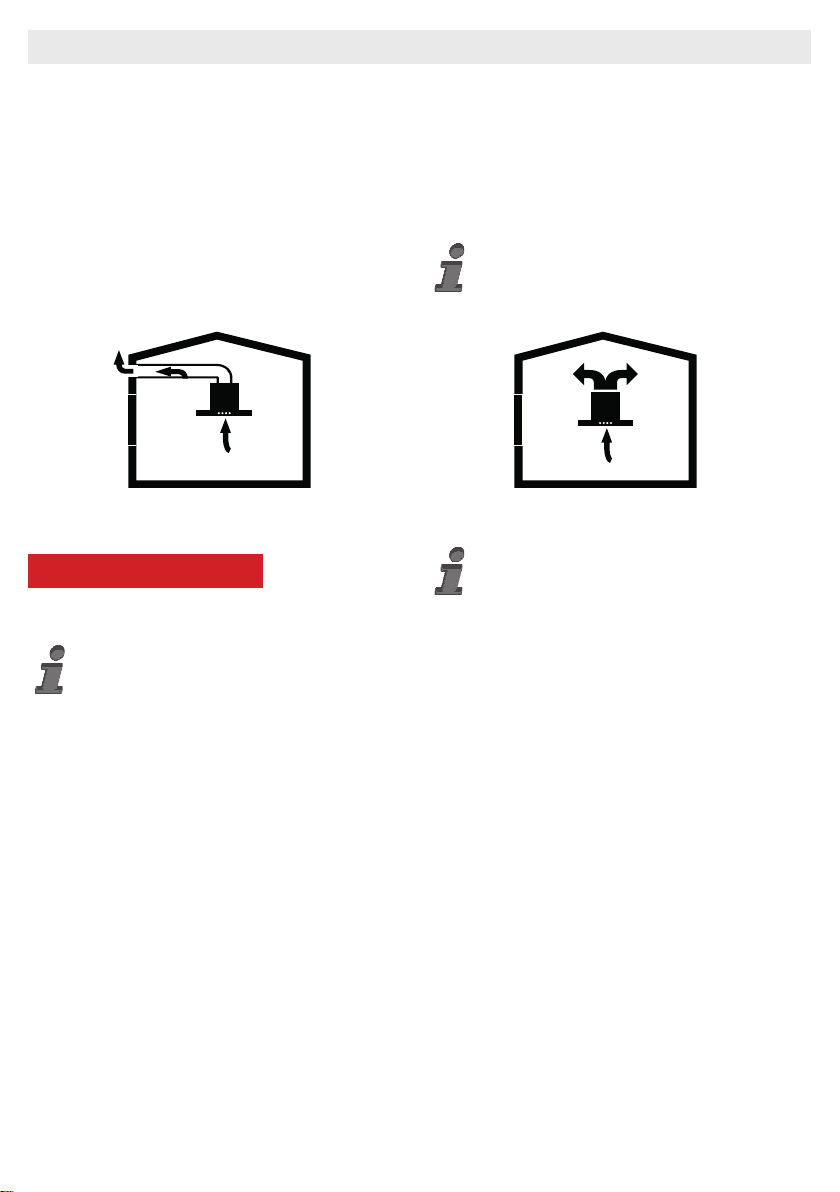
■Comply with the rules and instructions re-
garding discharge of outgoing air, stipulated by
the relevant authorities. (This warning does not
apply to uses without ue.)
■Flammable foods must not be cooked under
the appliance.
■Turn on the appliance after placing a sau-
cepan, pan, etc. on the cooker. Otherwise, high
temperature might lead to deformation on some
components of your product.
■Turn off the cooker’s burner before taking
the saucepan, pan, etc. off the cooker.
■Do not leave hot oil on your cooker. Pots
that contain hot oil might lead to inammation.
■ Since oils could catch re when you cook
fried foods in particular, be careful about your
curtains and tablecloths.
■ Ensure timely replacement of the lters. Fil-
ters not replaced in a timely manner pose risk
of re due to accumulated grease deposits on
them.
■ Do not use non-re-resistant ltering materi-
als instead of the lter.
■ Do not operate your product without lter,
and do not remove the lters when the product
is in use.
■ In case of any deagration, de-energize the
cooker hood and cooking appliances. (Plug off
the appliance or turn off the main switch).
■If your product’s periodic cleaning is not
made in a timely manner, it could pose risk of
re.
■De-energize the appliance before any ma-
intenance operations. (Plug off the appliance or
turn off the main switch.)
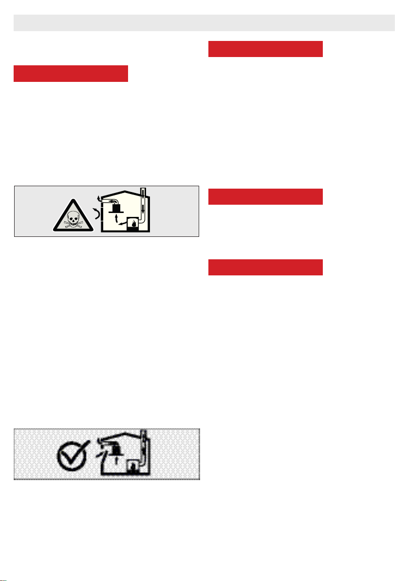
■When electric cooker hood and devices
fed with energies other than electricity opera-
te simultaneously, the negative pressure in the
room must not exceed 4 Pa ( 4 X 10 bar ).
■Gas or fuel oil burning appliances, such as
room heaters, which share the same environ-
WARNINGS AND SAFETY PRECAUTIONS

5
ment with your product, must be fully insulated
from the exhaust of this product or they must be
hermetical.
■ When you make a ue connection for your
product, use pipes with a diameter of 150mm
or 120 mm.
■The length of the pipe connection as well as
the number of elbows must be as minimum as
possible.
■Children should not tamper with the device.
■For your safety, use ”MAX 6 A” fuse in the
cooker hood system.
■Since the packing materials could be dan-
gerous, keep them away from children.
■If the feeder cable is damaged, it must be
replaced by its manufacturer or authorized te-
chnical service or any other personnel qualied
at the same level, in order to avoid any dange-
rous situation.
■ In case of any deagration, de-energize the
cooker hood and cooking appliances, and co-
ver the ame. Never use water to extinguish the
re.
■When cooking appliances are in operation,
their accessible parts could be hot.
■This appliance is not intended to be used
by people with physical, sensory and mental
disabilities (including children) or those who
have not adequate experience and knowledge
regarding its use, unless they are under the su-
pervision of a person responsible for the safety
of the appliance.
■After the installation of the cooker hood,
the minimum distance must be 65 cm between
the product and any electric cooker; and 75 cm
between it and any gas ranges or cookers bur-
ning other fuels.
■Output of the cooker hood must not be con-
nected to air ducts, where there exist another
smokes.
■You must be careful when using the appli-
ance spontaneously with other appliances (e.g.
gas, diesel fuels, coal or wood burning heaters,
shower heaters, etc.) which use the same air in
the same environment. It is because the cooker
hood could adversely affect the combustion, by
discharging the ambient air.
■This warning does not apply to uses without
ue.
■When electric cooker hood is used simulta-
neously with devices that use gas or other fuels,
there must be sufcient ventilation in the room
(might not apply to devices that discharges the
air back into the room).
■Simultaneous operation of more than one
gas cooker leads to generation of high heat. A
ventilation appliance placed on the surface of
cookers might therefore get damaged or burn.
Do not operate two gas cookers in high heat for
more than 15 minutes. One large burner with
more than 5kW (Work) power generates power
equal to that of two gas burners.
WARNINGS AND SAFETY PRECAUTIONS

6
WARNINGS AND SAFETY PRECAUTIONS
2.1 Life-Threatening Danger, Poiso-
ning Danger
A DANGER
There are life-threatening danger and poisoning
danger due to reabsorbed combustion gases.
During the air discharge outlet use, unless suf-
cient air supply is provided, do not use the appli-
ance simultaneously with devices that discharge
toxic gases through ue such as ventilated, gas,
oil, wood or coal burning heaters, shower hea-
ters, water heaters, etc.
Fig. 2: Poisoning Danger
Ventilated devices (e.g. gas, oil, wood or coal
burning heaters, shower heaters, water hea-
ters) take combustion air from the installation
location, and discharge the waste gas through
a waste gas system (e.g. ue). When the coo-
ker hood is active, it absorbs air from the kitchen
and neighbouring rooms. If adequate air entry is
not provided vacuum emerges. In such a case,
the toxic gases are absorbed from the ue
and waste gas channel, and are taken into to
door again. Fig. 2 Therefore, adequate fresh
air ingress must always be ensured. Fig. 3
Fig. 3
A DANGER
Fire danger!
Due to sparkling. Installation of appliance over
a heating device that is heated by using solid
fuels (for ex. wood or coal) is only allowed if an
non-detachable cover is present. For the instal-
lation process, attention must be paid to current
applicable construction regulations and regulati-
ons of local electric and gas companies.
Appliance might lead to re unless it is produced
in accordance with cleaning instructions.
A DANGER
2.2 Danger of electric shock!
Do not bend or jam the connection cable during
installation due to danger of damaged connecti-
on cable.
A DANGER
2.3 Danger of physical injury!
■During the installation, there is a danger
of physical injury due to the sharp edges. Use
protective gloves throughout the installation pro-
cess of the appliance.
■Due to risk of dropping the appliance, as-
sembly of all safety bolts and covers must be
performed as specied in the user manual.

7
LIFE-THREATENING DANGER, POISONING DANGER
A DANGER
2.4 Danger of burn, danger of
electric shock!
■Allow the appliance to cool before cleaning
or maintenance process. Switch off the fuse or
pull out the mains plug from the socket.
■There is risk of damage due to ingress of mo-
isture in the electronics. Do not clean the control
components with a wet cloth.
■The surface could be damaged due to a
wrong cleaning process. Clean stainless steel
surfaces only in their brushing direction. Do not
use a stainless steel cleaner for the control ele-
ments.
■The surface could be damaged due to agg-
ressive and abrasive cleaning agents. Never use
use aggressive and abrasive cleaning agents.
■ There is risk of damage due to backow
of condensate. Mount the air outlet channel
downwards from the appliance (slope of 1°).
A DANGER
2.5 Dangers of re and physical
injury!
In case of repairing that is not performed accord-
ing to the rules or as required, turn off the fuse
or unplug the feeder cable of your appliance.
Repairing must be performed only by the autho-
rized technical service or authorized experts.
NOTE
If the appliance is faulty or damages, turn off the
fuse or unplug the feeder cable of your appliance
and call the authorized service.
NOTE
If the feeder cable is damaged, it must be
replaced by its manufacturer or its authorized
technical service or any other personnel
qualied at the same level, in order to avoid any
dangerous situation.
NOTE
If the bulbs of your appliance are faulty, turn
off the fuse or unplug the feeder cable of your
appliance. Replace the bulbs immediately to
avoid overload on other bulbs (wait for the bulbs
to cool down rst)
A DANGER
Accessible components might be heated when
used with cooking devices.
A DANGER
Air outlet pipe of this appliance mustn’t be con-
nected in the ue used to discharge the fume
generated by devices that use gas or other fuels.

8
3 USAGES WITH AND WITHOUT CARBON
FILTER
You can use this appliance in exhaust air mode
and ventilated air mode.
Exhaust air mode
The absorbed air is cleaned by the grease lters,
and is discharged through a piping system. Fig.4
Fig. 4: Air Outlet without Carbon Filter
A WARNING
Death Risk!
Exhaust gases that are reabsorbed might lead to
poisoning. Exhaust air must not be transferred to
an active smoke or waste gas ue; or a ue used
for ventilation of the places, where heat sources
are installed.
■If you want to transfer exhaust air to an inac-
tive smoke or waste gas ue, you need to obtain
permission from an authorized chimney sweep.
■If exhaust air is discharged through the exter-
nal wall, a telescopic wall safe must be used.
Ventilated air mode
Absorbed air is cleaned by the grease
lters and an active carbon lter, and then
it is transferred back to the kitchen. Fig.5
Fig. 5: Air Outlet with Carbon Filter
To retain the substances that lead to
odour in ventilated air mode, you must
attach an active carbon lter. Consult your
authorized dealer for various options available
to use your appliance in ventilated air mode.
You can purchase the accessories required for
this process for related sales points, authorized
services or online sales centre
USAGE WITH AND WITHOUT CARBON FILTER

9
USAGE WITH AND WITHOUT CARBON FILTER
3.1 Replacement of Carbon Filter
In environments without ue, active carbon lter
must be used for ltering the air and resending
it in. Active carbon lter must be supplied from
service or your dealer. De-energize the applian-
ce before replacing the carbon lter. Since car-
bon lter is used in kitchens with no ue outlet,
it must be replaced in every 3-5 months depen-
ding on the use.
Carbon lter must never be washed. Grease l-
ters must be installed in the product, regardless
of whether or not carbon lters are used. Do not
use your product without grease lter.
3.2 Replacement of Carbon Filter
Fig. 6: CARBON FILTER
The appliance you have purchased is
appropriate for use with carbon lters.
1. Place the carbon lter in its housing. Fig. 6
2. Rotating the carbon lter clockwise,
ensure that it is completely t. Fig. 6
If carbon lter does not t in completely,
it might drop and damage your product.
A DANGER
Do not wash carbon lters. Keep the carbon l-
ters away from children.

10
CLEANING AND PREVENTIVE MAINTENANCE
4 CLEANING AND PREVENTI-
VE MAINTENANCE
A DANGER
■Prior to each maintenance and cleaning,
cooker hood must be unplugged, and
appliance must be dead
■Cleaning and user maintenance of
the appliance shall not be performed by
unattended children.
■The surface could be damaged due to
aggressive and abrasive cleaning agents.
Never use aggressive and abrasive cleaning
agents. Supply your cleaning and protective
substances that are appropriate for your
appliance from the authorized technical
service. Surface of appliance and control units
are sensitive to scratching.
■Clean the surfaces with a soft and damp
cloth, dish-washing liquid or mild glass
cleaning agent. Soften the dry, sticky dirt with a
damp cloth. Do not scrape!
■It is not appropriate to use dry cloths,
sponges that may scratch, materials that
require rubbing, and other aggressive cleaning
agents containing sand, soda, acid or chlorine.
■Clean the stainless steel surfaces in their
brushing direction only.
■Do not use stainless steel cleaning agents
and wet clothes for control units. Cleaning of
metal grease lters Used metal grease lters
retain the greasy particles in the moisture and
vapour generated in the kitchen. Clean the
metal grease lters about every three months,
under normal use conditions (1 to 2 hours a
day).
■Do not use excessively effective, acidic or
alkaline cleaning agents.
■ For cleaning the metal grease lters, clean
the holder parts of the metal grease lters in
the appliance, with a damp cloth as well.
■ You can clean the metal grease lters in the
dishwasher or by hand.
4.1 Washing in Dishwasher
■In case of washing in dishwasher, a slight
change might occur in colour. This has no effect
on the function of the metal grease lter.
■Do not wash the excessively dirty metal grea-
se lters together with dishes.
■ Place the metal grease lters loosely and fre-
ely in the dishwasher. Metal grease lters must
be placed in the dishwasher without jamming.
4.2 Hand Wash
For stubborn dirts, you can use a special
grease solvent. You can buy such an agent
from the authorized sales centre.
■ Soften the metal grease lters in a hot water
with dish-washing liquid.
■Use a brush for cleaning and wait for the liq-
uid in metal grease lters to ow off completely.
■ Rinse the lters thoroughly after cleaning.
A DANGER
Thanks to timely cleaning of metal grease lter,
the re danger caused by excessive heat that is
generated during frying is avoided.
4.3 Removal/Installation of Alumini-
um Filter
Pull the aluminium lter towards you by press-
ing on its tab. Reverse the process to install the
lter.

11
INSTALLATION OF APPLIANCE
5 INSTALLATION OF APPLIANCE
Fig. 7: INSTALLATION OF APPLIANCE
After completing the installation of cooker hood, the minimum distance must be 650 mm between
the product and any electric cooker; and 750 mm between it and any gas ranges or cookers burning
other fuels. Fig. 7
5.1 Installation and Unpacking of
the Appliance
Check that your appliance is not deformed.
■Report the transport issues immediately to
transport operator.
■Any faults encountered shall be reported to
the dealer, too.
■Do not allow children to play the with packa-
ging materials !!!
5.2 Recommendation for Energy
Saving
■Replace the carbon lters on a regular basis.
■Regularly clean your aluminium lters. Since
dirty lters would block the air passage, you mi-
ght have to use the appliance at a higher speed.
■Use your product according to its normal spe-
eds.
■Use at higher speed would cause an increase
in the energy consumption.

12
5.3 Exhaust Air Mode
A WARNING
Death Risk!
Exhaust gases that are reabsorbed might lead to
poisoning. Exhaust air must not be transferred to
an active smoke or waste gas ue; or a ue used
for ventilation of the places, where heat sources
are installed. If you want to transfer exhaust air
to an inactive smoke or waste gas ue, you need
to obtain permission from an authorized chim-
ney sweep.
If exhaust air is discharged over the external
wall, a telescopic wall case must be used..
5.4 Air Discharge Line
Information: Manufacturer of appliance can-
not be held responsible for defects caused by
laid pipes.
■Appliance shows the highest performance
when a short and at air outlet pipe and a pipe
diameter as large as possible is used.
■Optimum ventilation performance cannot be
reached and noise of fan increases when long
and rough air outlet pipes and multiple pipe el-
bows or pipe diameters smaller than 150mm are
used.
■Pipes or hoses used in laying the air outlet
line must be made of inammable materials.
Circular Pipes
It is recommended that inner diameter should be
150 mm or at least 120 mm.
Flat Channels
Inner Section must be appropriate to the diame-
ter of circular pipes.
Ø150 mm approx. 177 cm²
Ø150 mm approx. 173 cm²
■Flat channels shouldn’t have sharp elbows.
■Use sealing strips for different pipe diameters.
5.5 Checking the Wall
■ Wall must be at, straight and have the suf-
cient bearing capacity.
■Depth of drilling holes must comply with the
length of bolts. Dowels must t in properly.
■Bolts and dowels in the enclosure are ap-
propriate for use in rigid monolithic walls. Use
appropriate fasting materials for different const-
ructions (for ex. plasterboard, aerated concrete,
proton bricks).
■Maximum weight of your cooker hood is 40
Kg.
5.6 Electrical Connection
A WARNING
Electric Shock Danger!
Components in the appliance might have sharp
edges. Connection cable can be damaged. Do
not bend or jam the connection cable during in-
stallation.
Necessary connection data is provided on the
type label found inside your appliance; metal
grease lters must be removed to see the label.
Length of connection line: approx.
1.3 m
This appliance complies with EU interference
elimination guidelines.
A WARNING
5.7 Danger of Electric Shock!
It must always be possible to disconnect the
appliance from the electric network. Appliance
must be plugged in a protected contact outlet
that is mounted in accordance with the rules. If
the plug cannot be reached after installation or
during the required xed connection, there must
be many pole separation assemblies available
with at least 3 mm contact distance to the instal-
lation. Fixed connection must be performed by
an electronics expert only.
INSTALLATION OF APPLIANCE

13
CONTENT OF PACKAGE
6 CONTENT OF PACKAGE
Fig. 8: CONTENT OF PACKAGE
1. Product
2. Inner Flue
3. Outer Flue
4. 120mm Plastic Flue
5. Flue Connection Plate
6. User Manual
7. Assembly Pattern
8. 2x Ø6mm Plastic Dowel
9. x Ø10mm Plastic Dowel
10. 3x 5.5x60 Wall Mount Screw
11. 2x 3.9x22 Flue Connection Plate Screw
12. 3.5x9.5 Flue Connection Screw

14
OVERVIEW OF COOKER HOOD
7 OVERVIEW OF COOKER
HOOD
Fig. 9: OVERVIEW OF COOKER HOOD
1. Inner Flue
2. Outer Flue
3. Glass
4. Cooker Lighting
5. Control Panel Layout
6. Filter

15
ASSEMBLY OF PRODUCT
8 ASSEMBLY OF PRODUCT
8.1 Installation Diagram and Components
Fig. 10: ASSEMBLY INSTALLATION AND COMPONENTS
1. Inner Flue
2. Outer Flue
3. Product Hanging Plate
4. Product Hanging Plate Fixing Screw
5. Glass
6. 3x 5.5x60 Wall Mount Screw
7. 3x Ø10mm Plastic Dowel
8. 2x 3.9x22 Screw
9. Flue Connection Plate
10. 2x Ø6mm Plastic Dowel
■ Loosening the product hanging plate xing
screw (4) pull the hanging plates (3) upwards,
and x the hanging plated by re-tightening the
xing screw. Fig 10
■Assemble the cooker hood with the help of
the assembly scheme. (Fig. 8 / 7)
■ Afx the assembly pattern on the wall, at the
specied height (See the minimum and maxi-
mum distances intended for the worktop, in the
assembly pattern). Perforate points A, B and
C.(Fig. 10)
■ Insert Ø10mm dowels (7) into the holes drilled
as A, B, C and D, and screw down the screws
at the points A + B so that 5mm space remains
between the screw head and the wall. (Fig. 10)
■Hang it on the wall with the hanging plate of
the cooker hood.
■ Tighten A + B xing screws on the wall, and
completely secure the product at point C.

16
8.2 Assembly of Plastic Flue
Fig. 11: PLASTIC FLUE CONNECTION
1.120 mm Flue Adapter
2.Body
■ Attach the plastic ue (1) in the product body
(2), and rotate it in the arrow direction (Fig. 11).
■Make the air outlet connection of the product
ASSEMBLY OF PLASTİC FLUE

17
9 ASSEMBLY OF PLATE
FUELS
Fig. 12: ASSEMBLY OF PLATE FUELS
1.Inner Flue
2.Flue Connection Plate Fixing Screws
3.Flue Connection Plate
The outer and inner sheet metal ues are
assembled one within the other.
The cooker hood is set in the midst, and then
the ue connecting plate (3) is directly afxed to
the wall, under the cover or points E and F are
marked after performing a measurement. (Page
16 Fig.10)
Drill points E and F with Ø6mm drill bit, and in-
sert Ø6mm and plastic dowels. Insert the ue
connection plate with 3.9x22 screws (Page 16
Fig.10)
By pulling the inner ue (1) with screw (2) up-
wards and
left, screw it to the ue connection plate (3) on
the right and left (Fig.12).
ASSEMBLY OF PLATE FUELS

18
USE OF PRODUCT
10 USE OF PRODUCT
10.1 On Glass 3 Spd Touch Button
Fig. 11: Touch Button
1. Press this button to turn on the product.
When this button is pressed, product will also
operate at speed level 1 (Fig.11).
2. When this button is pressed, product will
operate at speed level 2 (Fig.11).
3. Dgt Display: You can see the operation rate
of product on this screen (Fig.11).
4. When this button is pressed, product will
operate at speed level 3 (Fig.11).
5. Press this button to turn on or off the lamp
(Fig.11).
To activate timer function, press and hold any of
buttons 1, 2 and 3 for 3 seconds. Then, 15 mi-
nute timer function will be activated and the pro-
duct will turn off automatically after 15 minutes.
All active functions operated prior to activation
of timer function will be deactivated after 15 mi-
nutes. All active functions operated after activa-
tion of timer function will be reactivated after 15
minutes.
10.2 Push Button
Fig. 12: Push Button
1. Press this button to reset the product.
2. When this button is pressed, product will
operate at speed level 1.
3. When this button is pressed, product will
operate at speed level 2.
4. When this button is pressed, product will
operate at speed level 3.
5. Press this button to turn on or off the lamp.
Cleaning Periods of the Metal Filter:
The lters must be cleaned when “C” signal ap-
pears on the display or (depending on usage)
after every 2-3 weeks. When the filters are
cleaned and mount-ed in their places, press
button ( ) for more than 3 seconds in order to
delete “C” signal (when the product is inactive).
Letter “E” will appear on the display, and the
product will switch to nor-mal operation. If it is
desired to
go on operation without deleting “C” signal, ac-
tive rate will appear for 1sec when ( ) button
is pressed and then, “C” signal will reappear
and motor will continue to operate.
“C” mark will appear at the end of the
product’s usage period of 60 hours.
This manual suits for next models
1
Table of contents
Other VOX electronics Ventilation Hood manuals

VOX electronics
VOX electronics BTG 620BL User manual

VOX electronics
VOX electronics TRD601W User manual

VOX electronics
VOX electronics CHM 650IX User manual

VOX electronics
VOX electronics PIO-600 W User manual

VOX electronics
VOX electronics PIO 650 2MW User manual

VOX electronics
VOX electronics CHM-950IX User manual

VOX electronics
VOX electronics TRD-650 W User manual

VOX electronics
VOX electronics PIO 650W User manual

VOX electronics
VOX electronics TRD-600 IX User manual