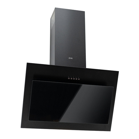
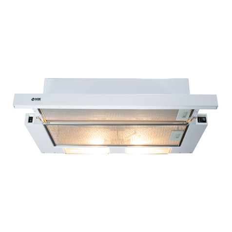
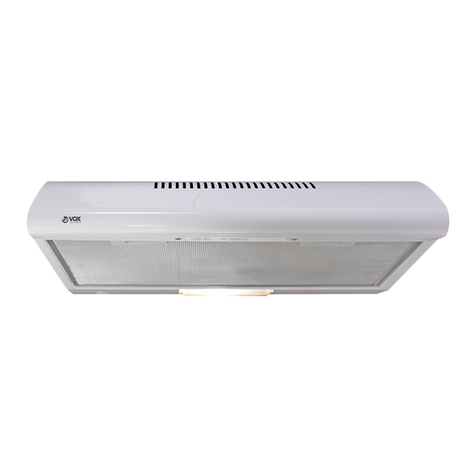
VOX electronics PIO-600 W User manual

PIO- 600 W
PIO- 600 IX
ISTRUZIONI D'USO APPA APRANT
OPERATING INSTRUCTIONS HOOD
UPUTTO A UPOTRU APRATOR
УПАTСТВА ЗА РАКУВАЊЕ АСПИРАТОР
UPUTSTVO ZA UPOTREBU APRATOR
ITA
GBR
SRB
MKD
BIH
MNE

ISTRUZIONI D'USO APPA APRANT
OPERATING INSTRUCTIONS HOOD
UPUTTO A UPOTRU APRATOR
УПАTСТВА ЗА РАКУВАЊЕ АСПИРАТОР
UPUTSTVO ZA UPOTREBU APRATOR

2
2
INDICE
CONSIGLI E SUGGERIMENTI.............................................................................................................................................. 3
CARATTERISTICHE.............................................................................................................................................................. 4
INSTALLAZIONE ................................................................................................................................................................... 5
USO........................................................................................................................................................................................ 7
MANUTENZIONE .................................................................................................................................................................. 8
INDEX
RECOMMENDATIONS AND SUGGESTIONS ..................................................................................................................... 9
CHARACTERISTICS ........................................................................................................................................................... 10
INSTALLATION.................................................................................................................................................................... 11
USE ...................................................................................................................................................................................... 13
MAINTENANCE................................................................................................................................................................... 14
ИНДЕКС
ПРЕПОРУКЕ ИСУГЕСТИЈЕ.............................................................................................................................................. 15
КАРАКТЕРИСТИКЕ ............................................................................................................................................................ 16
ИНСТАЛИРАЊЕ ................................................................................................................................................................. 17
УПОТРЕБА.......................................................................................................................................................................... 19
ОДРЖАВАЊЕ ..................................................................................................................................................................... 20
ИНДЕКС
СОВЕТИ ИТРИКОВИ......................................................................................................................................................... 21
КАРАКТЕРИСТИКИ ............................................................................................................................................................ 22
МОНТАЖА........................................................................................................................................................................... 23
КОРИСТЕТЕ........................................................................................................................................................................ 25
ОДРЖУВАЊЕ ..................................................................................................................................................................... 26
INDEKS
PREPORUKE I SUGESTIJE ............................................................................................................................................... 27
KARAKTERISTIKE .............................................................................................................................................................. 28
INSTALIRANJE.................................................................................................................................................................... 29
UPOTREBA.......................................................................................................................................................................... 31
ODRŽAVANJE..................................................................................................................................................................... 32
IT
EN
SR
МК
М
BS

IT 3
3
CONSIGLI E SUGGERIMENTI
Questo libretto di istruzioni per l'uso è previsto per più versioni dell' apparecchio. É possibile che siano
descritti singoli particolari della dotazione, che non riguardano il Vostro apparecchio.
INSTALLAZIONE
• Il produttore declina qualsiasi responsabilità per danni dovuti ad installazione non corretta o non conforme
alle regole dell’arte.
• La distanza minima di sicurezza tra il Piano di cottura e la Cappa deve essere di 650 mm, (alcuni modelli
possono essere installati ad un’altezza inferiore, fare riferimento ai paragrafi ingombro e installazione).
• Verificare che la tensione di rete corrisponda a quella riportata nella targhetta posta all’interno della Cappa.
• Per Apparecchi in Classe Iaaccertarsi che l’impianto elettrico domestico garantisca un corretto scarico a
terra.
• Collegare la Cappa all’uscita dell’aria aspirata con tubazione di diametro pari o superiore a 120 mm. Il
percorso della tubazione deve essere il più breve possibile.
• Non collegare la Cappa a condotti di scarico dei fumi prodotti da combustione (caldaie, caminetti, ecc.).
• Nel caso in cui nella stanza vengano utilizzati sia la Cappa che apparecchi non azionati da energia elettrica
(ad esempio apparecchi utilizzatori di gas), si deve provvedere ad una aerazione sufficiente dell’ambiente.
Se la cucina ne fosse sprovvista, praticare un’apertura che comunichi con l’esterno, per garantire il
richiamo d’aria pulita. Un uso proprio e senza rischi si ottiene quando la depressione massima del locale
non supera i 0,04 mBar.
• In caso di danneggiamento del cavo alimentazione, esso deve essere sostituito dal costruttore o dal
servizio di assistenza tecnica, in modo da prevenire ogni rischio.
• Se le istruzioni di installazione del dispositivo di cottura a gas indicano che è necessaria una distanza
maggiore di quella indicato sopra, è necessario tenerne conto. Bisogna rispettare tutte le normative relative
allo scarico dell’aria.
USO
• La Cappa è stata progettata esclusivamente per uso domestico, per abbattere gli odori della cucina.
• Non fare mai uso improprio della Cappa.
• Non lasciare fiamme libere a forte intensità sotto la Cappa in funzione.
• Regolare sempre le fiamme in modo da evitare una evidente fuoriuscita laterale delle stesse rispetto al
fondo delle pentole.
• Controllare le friggitrici durante l’uso: l’olio surriscaldato potrebbe infiammarsi.
• Non preparare alimenti flambè sotto la cappa da cucina; pericolo d'incendio.
• Questo apparecchio non deve essere utilizzato da persone (bambini inclusi) con ridotte capacità psichiche,
sensoriali o mentali, oppure da persone senza esperienza e conoscenza, a meno che non siano controllati
o istruiti all’uso dell’apparecchio da persone responsabili della loro sicurezza.
• I bambini devono essere supervisionati per assicurarsi che non giochino con l’apparecchio.
• “ATTENZIONE: Le parti accessibili possono diventare molto calde se utilizzate con degli apparecchi di
cottura.”
MANUTENZIONE
• Prima di procedere a qualsiasi operazione di manutenzione, disinserire la Cappa togliendo la spina
elettrica o spegnendo l’interruttore generale.
• Effettuare una scrupolosa e tempestiva manutenzione dei Filtri secondo gli intervalli consigliati (Rischio di
incendio).
• Per la pulizia delle superfici della Cappa è sufficiente utilizzare un panno umido e detersivo liquido neutro.
Il simbolo sul prodotto o sulla confezione indica che il prodotto non deve essere considerato come un normale rifiuto domestico, ma
deve essere portato nel punto di raccolta appropriato per il riciclaggio di apparecchiature elettriche ed elettroniche. Provvedendo a smaltire
questo prodotto in modo appropriato, si contribuisce a evitare potenziali conseguenze negative per l’ambiente e per la salute, che
potrebbero derivare da uno smaltimento inadeguato del prodotto. Per informazioni più dettagliate sul riciclaggio di questo prodotto,
contattare l’ufficio comunale, il servizio locale di smaltimento rifiuti o il negozio in cui è stato acquistato il prodotto.
2°

IT 4
4
CARATTERISTICHE
Min.
500mm
Min.
650mm
Componenti
Rif. Q.tà Componenti di Prodotto
11 Corpo Cappa completo di: Comandi, Luce, Gruppo Ventilatore,
Filtri
8 1 Griglia direzionata Uscita Aria
91 Flangia di riduzione D.150-120
20 1 Profilo chiusura
Rif. Q.tà Componenti di Installazione
12a 4 Viti 4,2 x 44,4
12e 2 Viti 2,9 x 9,5
Q.tà Documentazione
1 Libretto Istruzioni
1
12a
20
9
12e
8

IT 5
5
INSTALLAZIONE
Foratura Piano di supporto e Montaggio Cappa
MONTAGGIO CON VITI
• Il Piano di supporto della Cappa deve essere rien-
trante di 135 mm dal Piano inferiore dei Pensili.
• Forare ø 4,5 mm il supporto utilizzando la Dima di
foratura in dotazione.
• Praticare un foro ø 150 mm sul Piano di supporto,
utilizzando la Dima di foratura in dotazione.
• Fissare con 4 Viti 12a (4,2 x 44,4) in dotazione.
12a
135
150
PROFILO DI CHIUSURA
• Lo spazio tra il bordo della Cappa e la Parete di fon-
do può essere chiuso applicando il Profilo 20 in do-
tazione con le Viti già predisposte a questo scopo.
20
Connessioni
USCITA ARIA VERSIONE ASPIRANTE
Per installazione in Versione Aspirante collegare la
Cappa alla tubazione di uscita per mezzo di un tubo
rigido o flessibile di ø150 o 120 mm, la cui scelta è
lasciata all'installatore.
• Per collegamento con tubo ø120 mm, inserire la
Flangia di riduzione 9sull’Uscita del Corpo Cappa.
• Fissare il tubo con adeguate fascette stringitubo. Il
materiale occorrente non è in dotazione.
• Togliere eventuali Filtri Antiodore al Carbone attivo.
ø 150
9
ø 120

IT 6
6
USCITA ARIA VERSIONE FILTRANTE
• Praticare un foro ø 125 mm sull’eventuale Mensola
soprastante la Cappa.
• Inserire la Flangia di riduzione 9 sull’uscita del Cor-
po Cappa.
• Collegare la Flangia al foro di uscita sulla Mensola
soprastante la Cappa con un tubo rigido o flessibile di
ø120 mm.
• Fissare il tubo con adeguate fascette stringitubo. Il
materiale occorrente non è in dotazione.
• Fissare la Griglia direzionata 8 sull’uscita con 2 Viti
12e (2,9 x 9,5) in dotazione.
• Assicurarsi della presenza dei Filtri antiodore al Car-
bone attivo.
8
9
125
8
9
125
12e
CONNESSIONE ELETTRICA
• Collegare la Cappa all’Alimentazione di Rete interponendo un Interruttore bipolare con a-
pertura dei contatti di almeno 3 mm.
• Dopo aver installato la cappa è necessario per la prima volta aprire il carrello scorrevole e-
nergicamente fino a sentire lo scatto di fine corsa.

IT 7
7
USO
Quadro comandi
L Luci Accende e spegne l’Impianto
di Illuminazione.
M Motore Accende e spegne il motore
Aspirazione.
V Velocità Determina la velocità di
esercizio:
1. Velocità minima, adatta
ad un ricambio d’aria
continuo particolarmente
silenzioso, in presenza di
pochi vapori di cottura.
2. Velocità media, adatta
alla maggior parte delle
condizioni d’uso, dato
l’ottimo rapporto tra
portata d’aria trattata e
livello sonoro.
3. Velocità massima, adatta
a fronteggiare le massime
emissioni di vapore di
cottura, anche per tempi
prolungati.
L Luci Accende e spegne l’Impianto
di Illuminazione.
M Motore Accende e spegne il motore
Aspirazione.
V Velocità Determina la velocità di
esercizio:
1. Velocità minima, adatta
ad un ricambio d’aria
continuo particolarmente
silenzioso, in presenza di
pochi vapori di cottura.
2. Velocità media, adatta alla
maggior parte delle
condizioni d’uso, dato
l’ottimo rapporto tra
portata d’aria trattata e
livello sonoro.
L
M - V
0
1
0
1
2
3
L
M-V

IT 8
8
MANUTENZIONE
Filtri antigrasso
PULIZIA FILTRI ANTIGRASSO METALLICI AUTOPORTANTI
• Sono lavabili anche in lavastoviglie, e necessitano di essere lavati
ogni 2 mesi circa di utilizzo o più frequentemente, per un uso parti-
colarmente intenso.
• Estrarre il carrello aspirante.
• Togliere i Filtri uno alla volta, agendo sugli appositi agganci.
• Lavare i Filtri evitando di piegarli, e lasciarli asciugare prima di ri-
montarli. (Un’eventuale cambiamento del colore della superficie del
filtro, che potrebbe verificarsi nel tempo, non pregiudica assoluta-
mente l’efficienza dello stesso.)
• Rimontarli facendo attenzione a mantenere la maniglia verso la parte
visibile esterna.
• Chiudere il carrello aspirante.
Filtri antiodore (Versione Filtrante)
SOSTITUZIONE
Attenzione: Spegnere le luci ed attendere il raffreddamento delle lam-
pade prima di effettuare la sostituzione del filtro antiodore.
• Non sono lavabili né rigenerabili, vanno sostituiti ogni 4 mesi circa
di utilizzo o più frequentemente, per un uso particolarmente intenso.
• Estrarre il carrello aspirante.
• Togliere i Filtri Antigrasso
• Rimuovere il Filtro antiodore al Carbone attivo saturo, agendo sugli
appositi agganci.
• Rimontare i Filtri antigrasso.
• Richiudere il carrello aspirante.
Illuminazione
SOSTITUZIONE LAMPADE
Lampade da 28W-40W
• Togliere i Filtri antigrasso metallici.
• Svitare le Lampade e sostituirle con nuove di uguali caratteristiche.
• Rimontare i Filtri antigrasso metallici.

EN 9
9
RECOMMENDATIONS AND SUGGESTIONS
The Instructions for Use apply to several versions of this appliance. Accordingly, you may find
descriptions of individual features that do not apply to your specific appliance.
INSTALLATION
• The manufacturer will not be held liable for any damages resulting from incorrect or improper
installation.
• The minimum safety distance between the cooker top and the extractor hood is 650 mm (some
models can be installed at a lower height, please refer to the paragraphs on working dimensions
and installation).
• Check that the mains voltage corresponds to that indicated on the rating plate fixed to the inside of
the hood.
• For Class I appliances, check that the domestic power supply guarantees adequate earthing.
Connect the extractor to the exhaust flue through a pipe of minimum diameter 120 mm. The route
of the flue must be as short as possible.
• Do not connect the extractor hood to exhaust ducts carrying combustion fumes (boilers, fireplaces,
etc.).
• If the extractor is used in conjunction with non-electrical appliances (e.g. gas burning appliances), a
sufficient degree of aeration must be guaranteed in the room in order to prevent the backflow of
exhaust gas. The kitchen must have an opening communicating directly with the open air in order
to guarantee the entry of clean air. When the cooker hood is used in conjunction with appliances
supplied with energy other than electric, the negative pressure in the room must not exceed 0,04
mbar to prevent fumes being drawn back into the room by the cooker hood.
• In the event of damage to the power cable, it must be replaced by the manufacturer or by the
technical service department, in order to prevent any risks.
• If the instructions for installation for the gas hob specify a greater distance specified above, this has
to be taken into account. Regulations concerning the discharge of air have to be fulfilled.
USE
• The extractor hood has been designed exclusively for domestic use to eliminate kitchen smells.
• Never use the hood for purposes other than for which it has been designed.
• Never leave high naked flames under the hood when it is in operation.
• Adjust the flame intensity to direct it onto the bottom of the pan only, making sure that it does not
engulf the sides.
• Deep fat fryers must be continuously monitored during use: overheated oil can burst into flames.
• Do not flambè under the range hood; risk of fire
• This appliance is not intended for use by persons (including children) with reduced physical,
sensory or mental capabilities, or lack of experience and knowledge, unless they have been given
supervision or instruction concerning use of the appliance by a person responsible for their safety.
• Children should be supervised to ensure that they do not play with the appliance.
• “ CAUTION: Accessible parts may become hot when used with cooking appliances.”.
MAINTENANCE
• Switch off or unplug the appliance from the mains supply before carrying out any maintenance
work.
• Clean and/or replace the Filters after the specified time period (Fire hazard).
• Clean the hood using a damp cloth and a neutral liquid detergent.
The symbol on the product or on its packaging indicates that this product may not be treated as household waste. Instead it
shall be handed over to the applicable collection point for the recycling of electrical and electronic equipment. By ensuring this product
is disposed of correctly, you will help prevent potential negative consequences for the environment and human health, which could
otherwise be caused by inappropriate waste handling of this product. For more detailed information about recycling of this product,
please contact your local city office, your household waste disposal service or the shop where you purchased the product.
2°

EN 1
10
CHARACTERISTICS
Min.
500mm
Min.
650mm
Components
Ref. Q.ty Product Components
11 Hood Body, complete with: Controls, Light, Blower, Filters
81 Directional Air Outlet grille
91 Reducer Flange ø 150-120 mm
20 1 Closing element
Ref. Q.ty Installation Components
12a 4 Screws 4,2 x 44,4
12e 2 Screws 2,9 x 9,5
Q.ty Documentation
1 Instruction Manual
1
12a
20
9
12e
8

EN 1
11
INSTALLATION
Drilling the Support surface and Fitting the Hood
SCREW FITTING
• The hood support surface must be 135 mm above the
bottom surface of the wall units.
• Drill the support with a ø 4,5 mm drill bit, using the
drilling template provided.
• Cut a hole ø 150 mm in size on the support surface,
using the drilling template provided.
• Fix using the 4 screws 12a (4,2 x 44,4) provided.
12a
135
150
CLOSING ELEMENT
• The space between the edge of the hood and the rear
wall can be closed by applying the element 20 pro-
vided, using the screws supplied for this purpose.
20
Connections
DUCTED VERSION AIR EXHAUST SYSTEM
When installing the ducted version, connect the hood to
the chimney using either a flexible or rigid pipe ø 150 or
120 mm, the choice of which is left to the installer.
• To install a ø 120 mm air exhaust connection, insert
the reducer flange 9on the hood body outlet.
• Fix the pipe in position using sufficient pipe clamps
(not supplied).
• Remove possible charcoal filters.
ø 150
9
ø 120

EN 1
12
RECIRCULATION VERSION AIR OUTLET
• Cut a hole ø 125 mm in any shelf that may be posi-
tioned over the hood.
• Insert the reducer flange 9on the hood body outlet.
• Connect the flange to the outlet on the shelf over the
hood by using a flexible or rigid pipe ø120 mm.
• Fix the pipe in position using sufficient pipe clamps
(not supplied).
• Fix the air outlet grid 8on the recirculation air outlet
by using the 2 screws 12e (2,9 x 9,5) provided.
• Ensure that the activated charcoal filters have been
inserted.
8
9
125
8
9
125
12e
ELECTRICAL CONNECTION
• Connect the hood to the mains through a two-pole switch having a contact gap of at least 3
mm.
• When opening the sliding carriage for the first time after installing the hood, pull it out
briskly until it clicks.

EN 1
13
USE
Control panel
LLight Switches the lighting system
on and off.
MMotor Switches the extractor motor
on and off.
VSpeed Sets the operating speed of
the extractor:
1. Low speed, used for a
continuous and silent air
change in the presence of
light cooking vapour.
2. Medium speed, suitable
for most operating
conditions given the
optimum treated air
flow/noise level ratio.
3. Maximum speed, used for
eliminating the highest
cooking vapour emission,
including long periods.
LLight Switches the lighting system
on and off.
MMotor Switches the extractor motor
on and off.
VSpeed Sets the operating speed of
the extractor:
1. Low speed, used for a
continuous and silent air
change in the presence of
light cooking vapour.
2. Medium speed, suitable
for most operating
conditions given the
optimum treated air
flow/noise level ratio.
L
M - V
0
1
0
1
2
3
L
M-V

EN 1
14
MAINTENANCE
Grease filters
CLEANING METAL CASSETTE GREASE FILTERS
• The filters must be cleaned every 2 months, or more frequently in case
of particularly heavy use of the hood. Filters can be washed in a dish-
washer.
• Pull out the sliding suction panel.
• Remove the filters one by one, after having disconnected the relative
fastening elements.
• Wash the filters, taking care not to bend them. Let them get dry before
refitting them. (The colour of the filter surface may change throughout
the time but this has no influence to the filter efficiency).
• When refitting the filters, make sure that the handle is visible on the
outside.
• Close the sliding suction panel.
Charcoal filter (Recycling version)
REPLACING CHARCOAL FILTERS
Warning: Turn the lights off and wait until the lamps cool down before
you change the odour filter.
• These filters are not washable and cannot be regenerated, and must be
replaced approximately every four months or more frequently by par-
ticularly heavy use.
• Pull out the sliding suction panel.
• Remove the grease filters.
• Remove the saturated carbon filter by releasing the fixing hooks
• Fit the new filter by hooking it into its seating.
• Replace the grease filters.
• Close the sliding suction panel.
Lighting
LIGHT REPLACEMENT
28W-40W light.
• Remove the metal grease filters.
• Unscrew the bulbs and replace them with new ones having the same
characteristics.
• Replace the metal grease filters.

SR 1
15
ПРЕПОРУКЕ ИСУГЕСТИЈЕ
Ово упутство за употребу важи за неколико модела овог уређаја. Због тога се описи појединих
функција можда не односе на Ваш конкретан модел.
ИНСТАЛИРАЊЕ
• Произвођач неће бити одговоран ни за какву штету насталу услед неправилне или
неодговарајуће инсталације.
• Минимална безбедна удаљеност између горње површине штедњака иаспиратора је 650 mm
(неки модели се могу поставити иниже, погледајте одељке орадним димензијама и
постављању).
• Проверите да ли напон напајања одговара ономе који је назначен на натписној плочици са
унутрашње стране аспиратора.
• Услучају уређаја 1. класе проверите да ли струјна утичница може да обезбеди адекватно
уземљење.
Прикључите аспиратор на вентилациону цев помоћу цеви пречника бар 120 mm. Цев мора бити
што је могуће краћа.
• Не прикључујте аспиратор на издувне цеви кроз које пролазе продукти сагоревања (нпр. из
котлова икамина).
• Ако се аспиратор користи заједно са неелектричним уређајима (нпр. уређаји који сагоревају гас), мора се
обезбедити довољна проветреност просторије да би се спречио повратни ток издувног гаса. Укухињи
мора да постоји отвор за директан улазак ваздуха како би се обезбедио неометан улазак свежег ваздуха.
Када се аспиратор користи заједно са уређајима који не користе електричну енергију, негативан притисак у
просторији не сме прећи 0,04 mbar да се испарења не би враћала кроз аспиратор упросторију.
• Ако се кабл за напајање оштети, мора га заменити произвођач или техничка служба како би се
предупредиле све опасности.
• Ако је уупутству за постављање гасног штедњака наведено неопходно растојање које је веће од
горенаведеног, то се свакако мора узети уобзир. Морају се поштовати сви прописи осистемима
за вентилацију.
УПОТРЕБА
• Аспиратор је пројектован искључиво за уклањање кухињских мириса удомаћинству.
• Никад не користите аспиратор за било шта осим за оно за шта је намењен.
• Никад не остављајте отворени пламен испод укљученог аспиратора.
• Подесите интензитет пламена тако да буде усмерен само на дно тигања, ане да обухвати и
његове бочне стране.
• Фритезе се током употребе морају непрекидно надзирати: прегрејано уље може да се запали.
• Не фламбирајте намирнице испод аспиратора; опасност од ватре.
• Овај уређај не треба да користе особе (укључујући идецу) са смањеним физичким, чулним или
менталним способностима, као иособе које немају довољно искуства изнања, сем ако их
надзиру или оупотреби уређаја саветују особе одговорне за њихову безбедност.
• Деца морају бити под надзором да се не би играла са уређајем.
• „ОПРЕЗ: Приступачни делови могу постати врели кад се користе заједно са апаратима за кување.”
ОДРЖАВАЊЕ
• Искључите уређај или га раздвојите од извора напајања пре било каквог рада на одржавању.
• Очистите и/или замените филтере након одређеног временског периода (опасност од ватре).
• Аспиратор чистите влажном крпом инеутралним течним детерџентом.
Симбол на производу или његовој амбалажи означава да се он не сме сматрати обичним кућним отпадом. Уместо
тога мора се предати на одговарајућем месту служби за рециклажу електричних иелектронских уређаја. Обезбеђивањем
правилног уклањања овог производа допринећете спречавању потенцијалних негативних последица по животну средину
издравље људи, до чега би могло доћи услучају његовог неодговарајућег уклањања. За детаљније информације о
рециклажи овог производа обратите се локалној управи, служби за одношење смећа или продавници укојој сте купили
производ.
2°

SR 1
16
КАРАКТЕРИСТИКЕ
Min.
500mm
Min.
650mm
Делови
Озн. Кол. Делови производа
11 Тело аспиратора, заједно са: командама, осветљењем, венти-
латором ифилтерима
81 Решетка усмеривача одвода ваздуха
91 Редуцир прирубница ø150-120 mm
20 1 Затварачки елемент
Озн. Кол. Делови за монтажу
12a 4 Завртњи 4,2 x 44,4
12e 2 Завртњи 2,9 x 9,5
Кол. Документација
1 Упутство за употребу
1
12a
20
9
12e
8

SR 1
17
ИНСТАЛИРАЊЕ
Бушење носеће површи ипричвршћивање аспи-
ратора
ПОСТАВЉАЊЕ ЗАВРТЊЕВА
• Носећа површ за аспиратор мора бити 135 mm
изнад доње површине уградног елемента.
• Избушите носећу површ бургијом ø 4,5 mm
користећи приложени шаблон.
• Исеците отвор ø 150 mm на носећој површи
користећи приложени шаблон.
• Причврстите аспиратор помоћу 4 приложена за-
вртња 12a (4,2 x 44,4).
12a
135
150
ЗАТВАРАЧКИ ЕЛЕМЕНТ
• Простор између ивице аспиратора изида може се
затворити приложеним елементом бр. 20 помоћу у
ту сврху приложених завртњева.
20
Прикључци
ВЕНТИЛАЦИОНИ СИСТЕМ СА ОДВОДНОМ ЦЕВИ
При постављању модела за издувавање причврстите
тело аспиратора за димњак користећи савитљиву или
чврсту цев ø 150 или 120 mm по избору инсталатера.
• Да бисте инсталирали издувну цев ø 120 mm,
причврстите редукциону спојницу 9на отвор
аспиратора.
• Фиксирајте цев помоћу одговарајућих обујмица
(нису приложене).
• Уклоните све филтере са активним угљем.
ø 150
9
ø 120

SR 1
18
ОДВОД ВАЗДУХА КОД ВЕРЗИЈЕ ЗА РЕЦИРКУЛАЦИЈУ
• Исеците отвор ø 125 mm уполици која се налази
изнад аспиратора.
• Поставите редуцир прирубницу 9на одвод
ваздуха на телу аспиратора.
• Спојите прирубницу са отвором на полици изнад
аспиратора помоћу савитљиве или чврсте цеви
ø120 mm.
• Фиксирајте цев помоћу одговарајућих обујмица
(нису приложене).
• Причврстите издувну решетку 8на отвор за
рециркулацију ваздуха помоћу 2 приложена
завртња 12e (2,9 x 9,5).
• Уверите се да су стављени филтери са активним
угљем.
8
9
125
8
9
125
12e
ЕЛЕКТРИЧНИ ПРИКЉУЧАК
• Прикључите аспиратор уструју преко двополног прекидача код кога је растојање
између контаката бар 3 mm.
• Када први пут отварате клизни склоп након постављања аспиратора, извуците га тако
да шкљоцне.

SR 1
19
УПОТРЕБА
Контролна табла
LОсветљење Укључује иискључује
сијалице.
MМотор Укључује иискључује
мотор аспиратора.
VБрзина Подешава брзину рада
аспиратора:
1. Мала брзина, користи
се за непрекидан и
нечујан проток ваздуха
услучају мале количине
кухињских испарења.
2. Средња брзина, погодна
за већину радних
услова, пружа
оптималан однос
количине ваздуха и
буке.
3. Највећа брзина, користи
се за уклањање највећих
количина кухињских
испарења, чак иу
дужем периоду.
LОсветљење Укључује иискључује
сијалице.
MМотор Укључује иискључује
мотор аспиратора.
VБрзина Подешава брзину рада
аспиратора:
1. Мала брзина, користи
се за непрекидан и
нечујан проток ваздуха
услучају мале количине
кухињских испарења.
2. Средња брзина, погодна
за већину радних
услова, пружа
оптималан однос
количине ваздуха и
буке.
L
M - V
0
1
0
1
2
3
L
M-V
This manual suits for next models
1
Table of contents
Languages:
Other VOX electronics Ventilation Hood manuals

VOX electronics
VOX electronics CGL650IX User manual

VOX electronics
VOX electronics PIO 650 2MW User manual

VOX electronics
VOX electronics TRD601W User manual

VOX electronics
VOX electronics BTG 620BL User manual

VOX electronics
VOX electronics TRD-600 IX User manual

VOX electronics
VOX electronics CHM 650IX User manual

VOX electronics
VOX electronics TRD-650 W User manual

VOX electronics
VOX electronics PIO 650W User manual

VOX electronics
VOX electronics CHM-950IX User manual