4
Rev.09/01/2021
CR338
Installation
123
6 75
4
8
click or scan QR code
for installation video
Back to Table of Contents
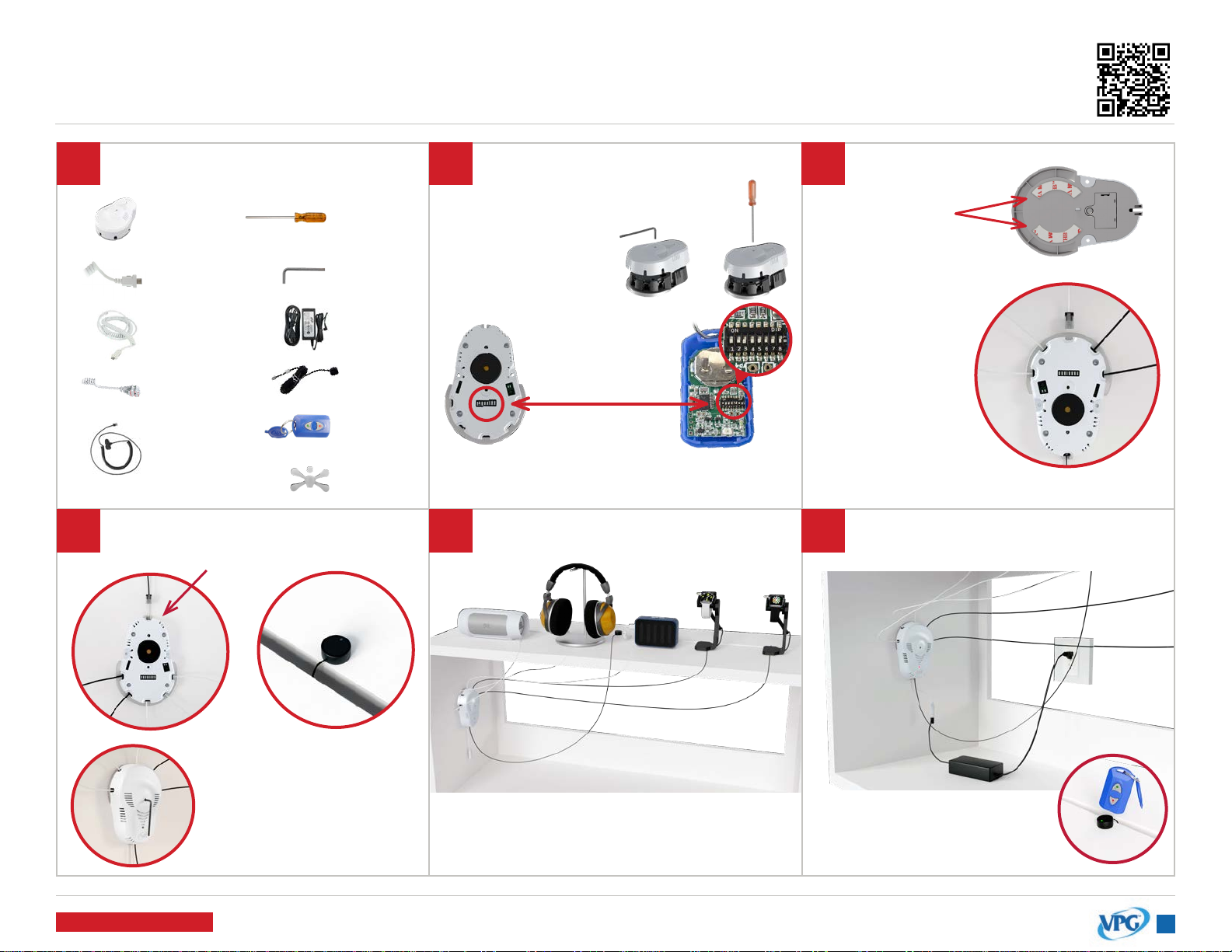
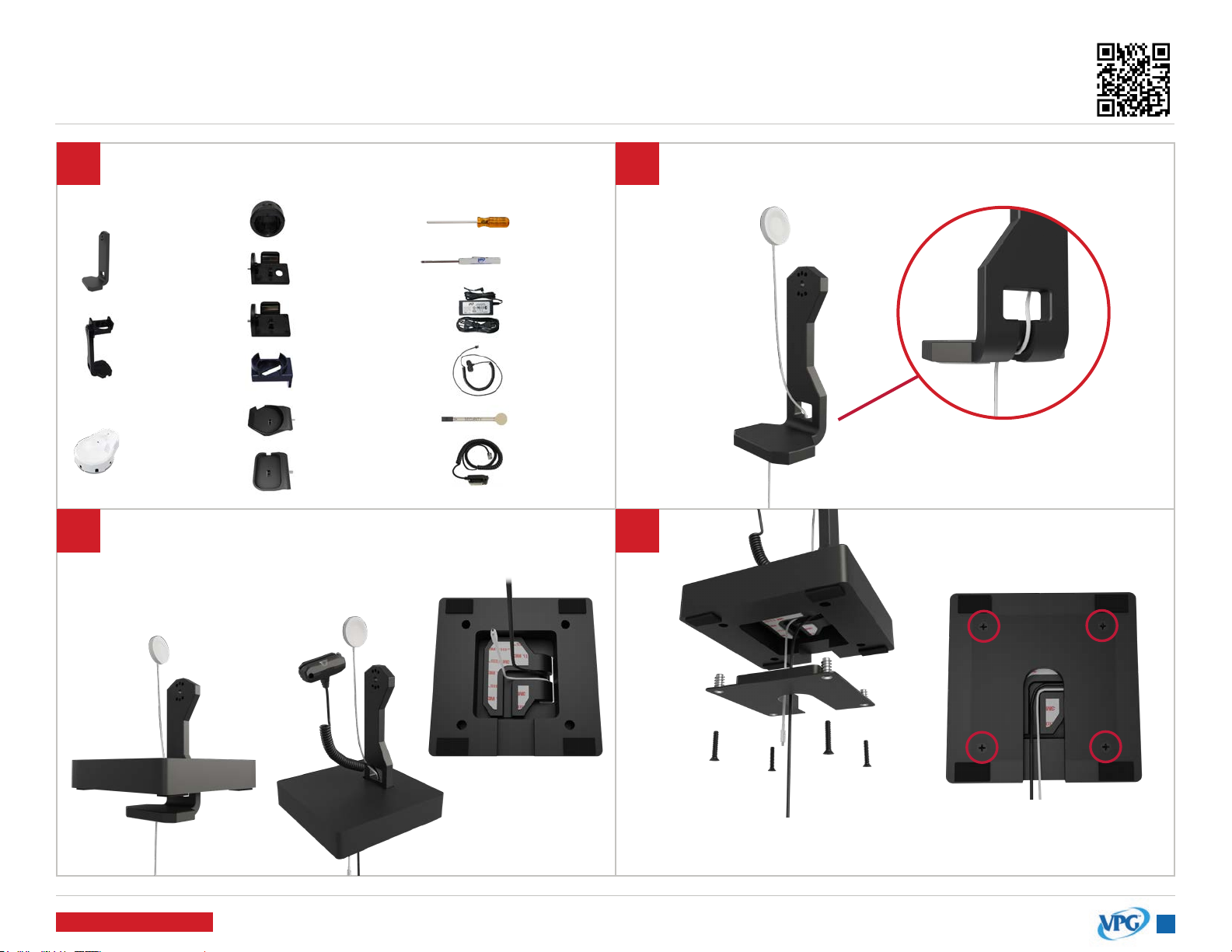
Tools & Parts Needed
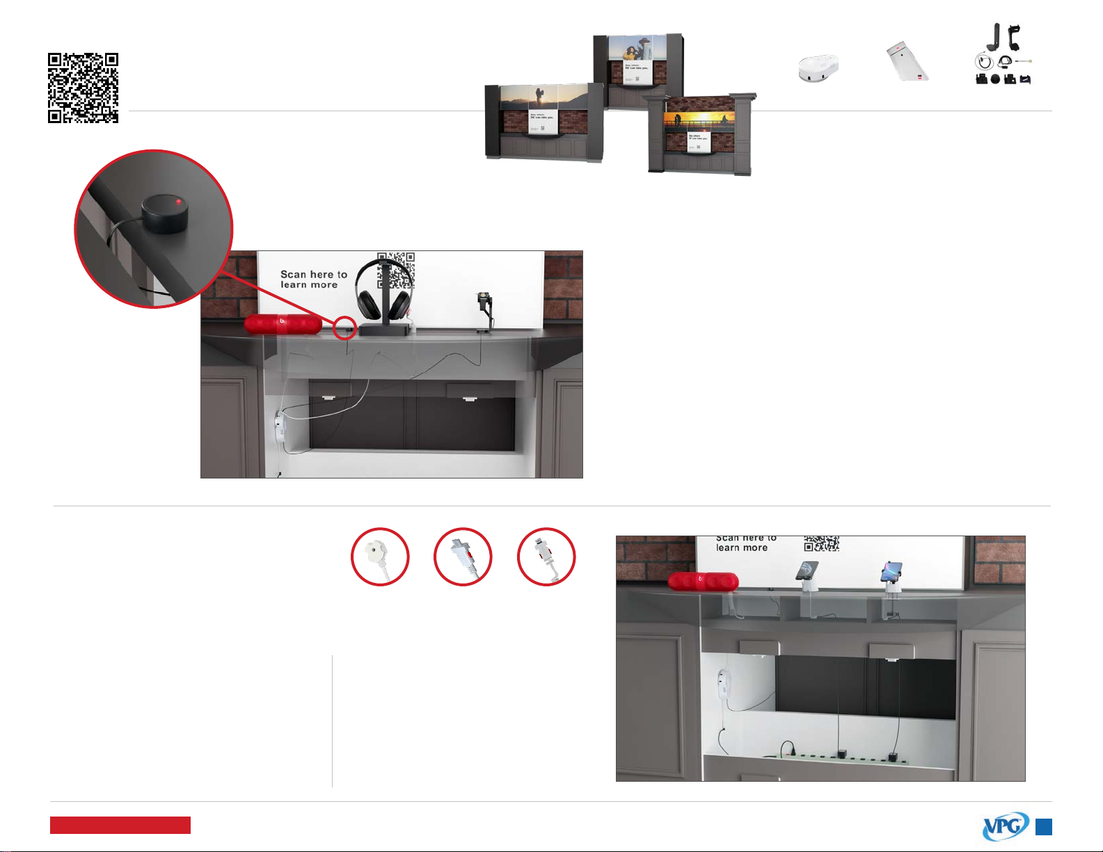
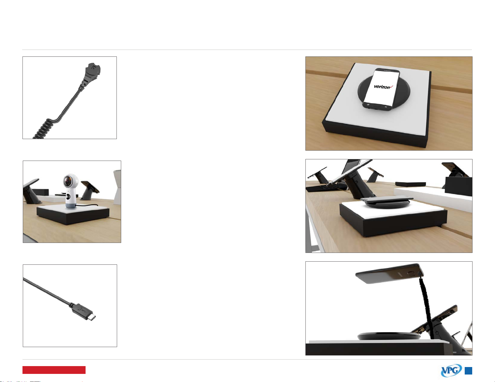
Arm the system
by pressing the
red “lock” button
on the IR Keyfob
(KF-1106). Point
the keyfob near
the black receiver
above the LED.
Plug the power
supply into the
pedestal and
into an AC
outlet.
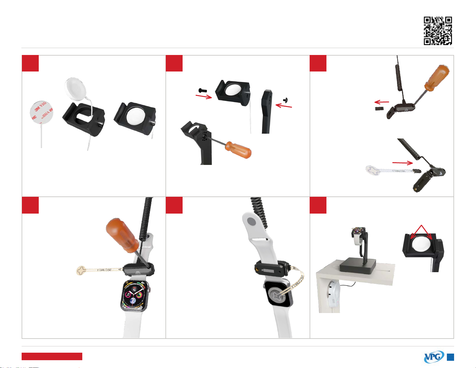
Make sure the tamper switch
is fully depressed and properly
aligned before mounting.
CORRECTINCORRECT
Side View
Clean xture surface and wipe dry.
Remove the adhesive liner on the
base of the pedestal and adhere
the pedestal to the xture.
IMPORTANT: Hold for 30 seconds to
ensure a strong bond.
Bottom View
System is on battery only if LED is
ashing quickly. Must have power
plugged in to arm the system.
Tamper Switch
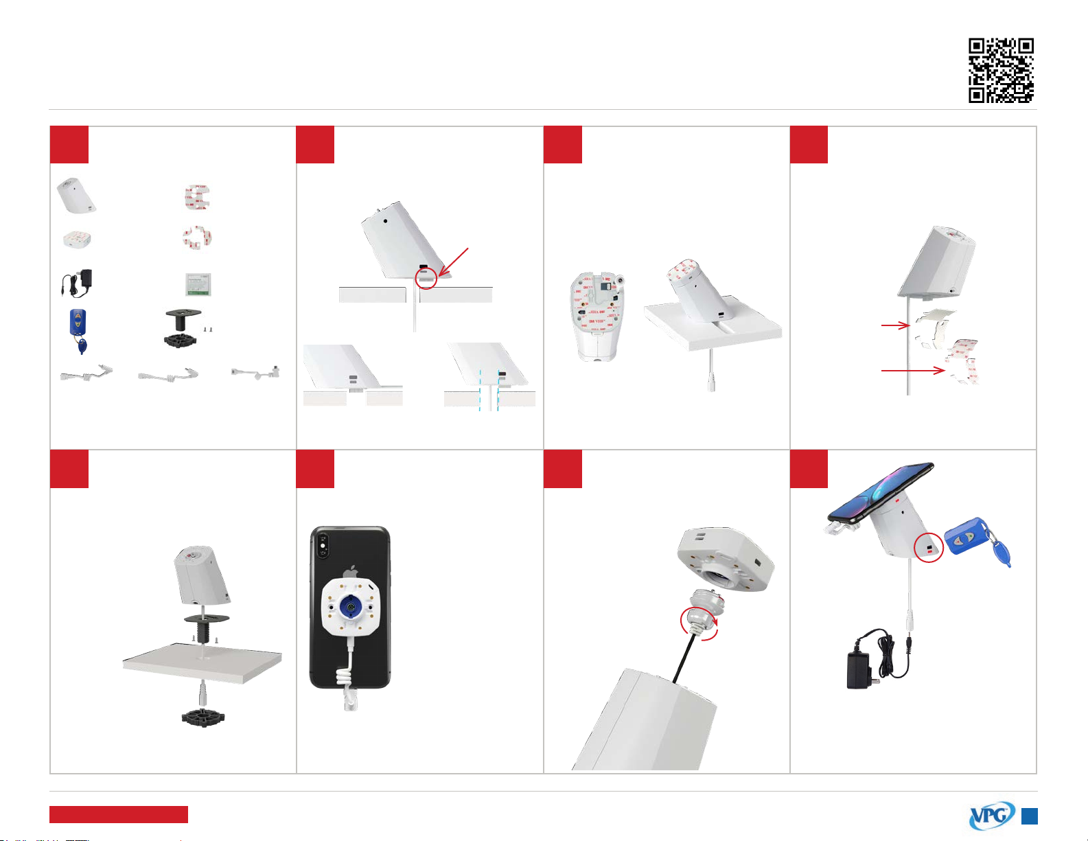
ADHESIVE MOUNTING
(for xtures WITHOUT overlay) ADAPTER MOUNTING
(for xtures WITH overlay)
Adhesive Tape
Adhesive Liner
ADAPTER MOUNTING
(for xtures WITH overlay)
A. Thread the pedestal power cord
through the adapter and screw to
the bottom
of the pedestal.
B. Place
connected
pedestal and
adapter through the hole in the
xture and tighten nut.
VP-1751W AD-238-8
oror
KF-1106
AD-239-5
AP-001-200
VP-1707W
V-39
P-21012 P-21006 P-21002
*K-1140
*Single Hole Adapter may come installed
on pedestal.
IMPORTANT: This step & step 5A are
necessary if the single hole adapter
is NOT already installed on the
CR338 pedestal.
Fully remove both the adhesive liner
and the tape from the bottom of
the pedestal.
Plug the power
coupler into sensor
and device.
*if coupler is not plugged
in, system will not alarm.
Remove adhesive
liner on sensor and
adhere to the center
of the device.
Clean the back of the
device with an alcohol pad
and wipe dry.
Attach the sensor to the
pedestal by twisting the boot
into the sensor.
IMPORTANT: If you are securing a
glass back device, see page 8 prior
to adhering sensor.