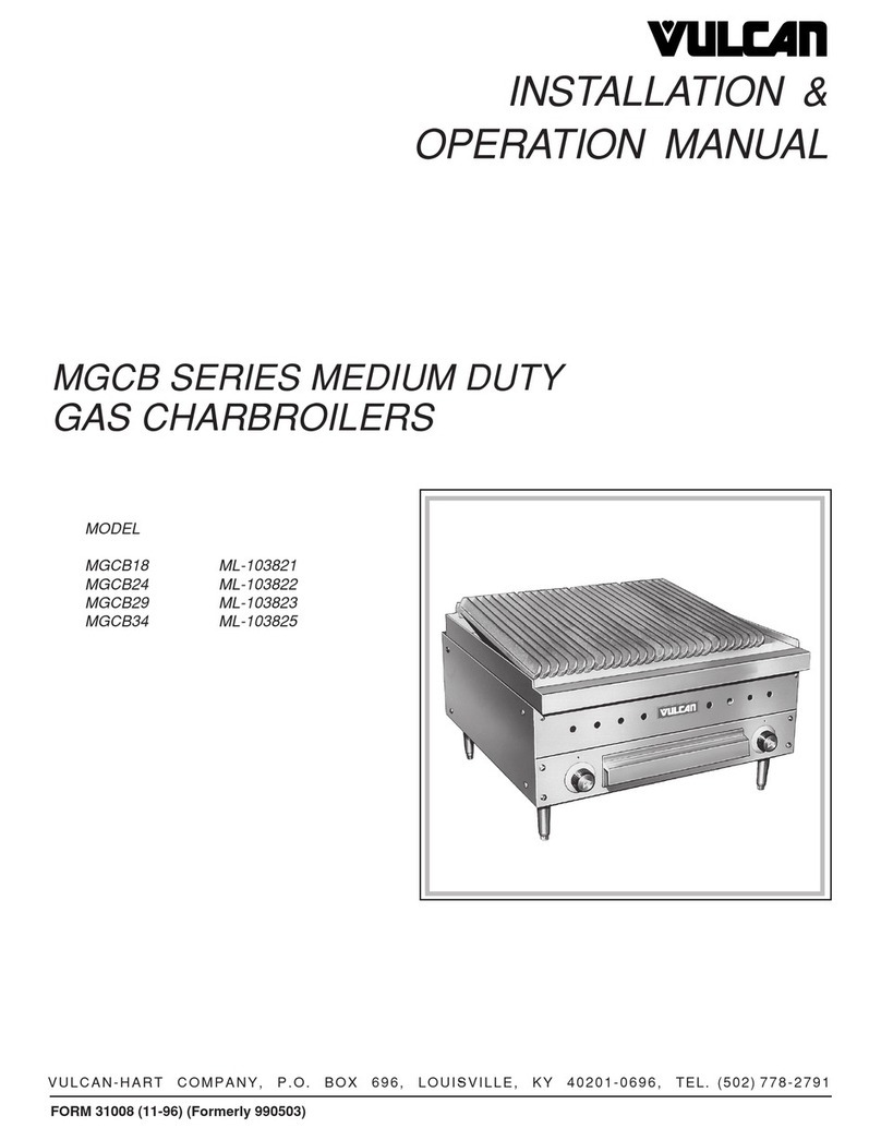
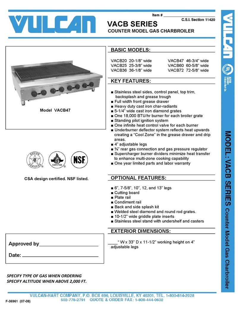
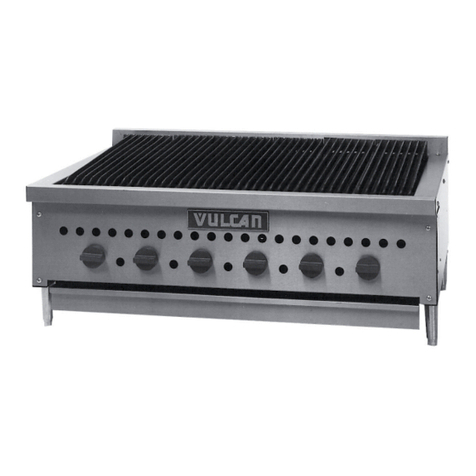
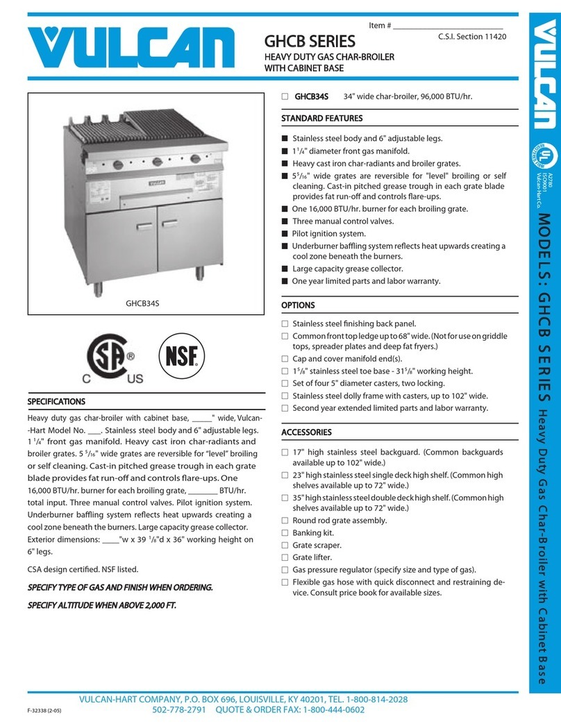
Vulcan-Hart VACB25 User manual

©ITW Food Equipment Group, LLC
3600 North Point Blvd.
Baltimore, MD 21222
RETAIN THIS MANUAL FOR FUTURE USE
FORM F38328 (3-13)
INSTALLATION & OPERATION MANUAL
GAS CHARBROILERS
MODELS
VACB25
VACB36
VACB47
VACB60
VACB72
ACB25
ACB36
ACB47
ACB60
ACB72
VACB36
ACB36

- 2-
IMPORTANT FOR YOUR SAFETY
THIS MANUAL HAS BEEN PREPARED FOR PERSONNEL QUALIFIED TO
INSTALL GAS EQUIPMENT, WHO SHOULD PERFORM THE INITIAL FIELD
START-UP AND ADJUSTMENTS OF THE EQUIPMENT COVERED BY THIS
MANUAL.
POST IN A PROMINENT LOCATION THE INSTRUCTIONS TO BE FOLLOWED IN
THE EVENT THE SMELL OF GAS IS DETECTED. THIS INFORMATION CAN BE
OBTAINED FROM THE LOCAL GAS SUPPLIER.
IMPORTANT
IN THE EVENT A GAS ODOR IS DETECTED, SHUT
DOWN UNITS AT MAIN SHUTOFF VALVE AND
CONTACT THE LOCAL GAS COMPANY OR GAS
SUPPLIER FOR SERVICE.
FOR YOUR SAFETY
DO NOT STORE OR USE GASOLINE OR OTHER
FLAMMABLE VAPORS OR LIQUIDS IN THE VICINITY OF
THIS OR ANY OTHER APPLIANCE.
IN THE EVENT OF A POWER FAILURE, DO NOT ATTEMPT TO OPERATE THIS DEVICE.
Improper installation,
adjustment, alteration, service or maintenance
can cause property damage, injury, or death.
Read the installation, operating and maintenance
instructions thoroughly before installing or
servicing this equipment.

- 3-
INSTALLATION, OPERATION AND CARE OF
GAS COUNTERTOP CHARBROILERS
GENERAL
Vulcan/Wolf Gas Countertop Charbroilers are designed for commercial use only and
feature fast, efficient gas heat. Each burner is controlled by an adjustable gas valve.
Cast radiants are located directly above each burner to maintain uniform temperature.
Radiants are easily removed for cleaning when cool.
Heavy-duty cast iron top grates are reversible to allow all or part of the cooking grid
surface to be level or sloped. A crumb tray is provided to collect fat run-off and debris;
it opens to the front for inspection or cleaning.
Model Number of Burners
Natural Gas BTU/hr
Input Rating
LP Gas BTU/hr
Input Rating
VACB25 / ACB25 4 68,000 64,000
VACB36 / ACB36 6 102,000 96,000
VACB48 / ACB48 8 136,000 128,000
VACB60 / ACB60 11 187,000 176,000
VACB72 / ACB72 13 221,000 208,000
INSTALLATION
UNPACKING
Immediately after unpacking, check for possible shipping damage. If the broiler is found
to be damaged, save the packaging material and contact the carrier within 15 days of
delivery.
Carefully unpack your charbroiler and make sure that no parts are discarded with
packaging material. A pressure regulator designed to operate with the broiler has been
supplied and must be installed before the charbroiler is placed into service (Refer to GAS
PRESSURE REGULATOR INSTALLATION in this manual).
Before installing, verify that the type of gas (natural or propane) and the clearance
dimensions agree with the specifications on the rating plate which is located on the lower
front corner on the right side.

- 4-
LOCATION
The installation location must be kept free and clear of combustibles. Do not obstruct the
flow of combustion and ventilation air. DO NOT install the charbroiler adjacent to open
burners or fryers.
Sufficient air should be allowed to enter the room to compensate for the amount of air
removed by any ventilating system and for combustion of the gas burners. Do not
obstruct the air flow into and around the appliance. Do not obstruct the flow of flue gases
through and above the broiler's top grate. Position the broiler in its final location. Check
that there are sufficient clearances to service the broiler and to make the required gas
supply connection(s). Provide 24" clearance at the front for cleaning, maintenance,
service and proper operation.
This broiler is for use in non-combustible locations only.
Minimum clearances to non-combustible walls are 3" to the rear and 3" to the sides.
INSTALLATION CODES AND STANDARDS
The Charbroiler must be installed in accordance with:
In the United States of America:
1. State and local codes.
2. National Fuel Gas Code, ANSI-Z223.1/NFPA #54 (latest edition). This shall include but
not be limited to: NFPA #54 Section 10.3.5.2 for Venting. Copies may be obtained
from The American Gas Association Accredited Standards Committee Z223, @ 400
N. Capital St. NW, Washington, DC 20001 or the Secretary Standards Council, NFPA,
1 Batterymarch Park Quincy, MA 02169-7471
NOTE: In the Commonwealth of Massachusetts
All gas appliances vented through a ventilation hood or exhaust system equipped with
a damper or with a power means of exhaust shall comply with 248 CMR.
3. NFPA Standard # 96 Vapor Removal from Cooking Equipment, latest edition, available
from the National Fire Protection Association, Batterymarch Park, Quincy, MA 02269.
In Canada:
1. Local codes.
2. CAN/CSA-B149.1 Natural Gas Installation (latest edition)
3. CAN/CSA-B149.2 Propane Installation Code (latest edition), available from the
Canadian Gas Association, 178 Rexdale Blvd., Etobicoke, Ontario, Canada M9W 1R3

- 5-
KEY COMPONENTS
Crumb Tray Fig. 1
Burner
Radiant
Grate
Super Charge
r
Burner Divide
r
Deflector Tray
Hook
Slot
Fig. 2
Enlarged View of Hook
Engaged In Slot
Supercharger Guide
Fig. 3
The charbroiler
and its parts are hot. Use care
when operating, cleaning or
servicing the charbroiler.
Grate – The grates can be utilized
flat or sloped for operational
flexibility.
Deflector Tray – The deflector tray
is the removable pan with holes in
it. The deflector tray deflects heat
back toward the cooking surface
while allowing debris to pass
through the holes and into the
crumb tray below. The deflector
tray should always be in place
above the crumb tray when
operating.
Crumb tray – The crumb tray is the
removable pan without holes in it.
The crumb tray catches any debris
that passes thru the deflector tray
and should always be installed
beneath the deflector tray. (Fig. 1).
Supercharger Burner Divider -
These act as dividers between
cooking zones to offer flexibility in
cooking and help direct heat
upwards to provide for a even
heating pattern. You may remove
some or all of the supercharger
burner dividers at your discretion if
you find your production method
works better without them. The
super charger burner dividers are
installed by inserting the hooks
thru corresponding slots at the
front (Fig. 2) and the back rests in
the super charger guide to the
rear. (Fig. 3).

- 6-
Radiant – The charbroiler must
never be operated without the
radiants in place. They protect the
burner from food drippings and
heat up to provide an even heating
pattern. The radiants are installed
by inserting the tab thru the
corresponding slot in the heat
shield to the front (Fig. 4-A) and
the back of the radiants set on the
radiant rest to the rear (Fig. 5-A).
Burner – The burner shutter
should engage the orifice to the
front (Fig. 6) and rest in the
burner slot to the rear of the unit.
Proper burner shutter adjustment
is important for optimal charbroiler
performance. The burner shutters
should only be adjusted with all
radiants in place. The shutter will
typically be about 50% open for
natural gas and 80 to 100% open
for LP. A properly adjusted burner
should exhibit solid blue flames
that are touching the burner. All
traces of yellow should be
adjusted out of the burner flame
for natural gas and only a slight
yellow tipping should be observed
on LP gas. Large, yellow tipped
flames typically indicate not
enough air and the burner shutters
should be opened slightly.
Floating flames (not touching the
burner) typically indicate too much
air and the shutter should be
closed slightly.
Fig. 4
Fig. 5
Fig. 6
Radiant Tab
Heat Shield Slot
Radiant Rest
Burner Shutter
Orifice
Burner Valve
A
B
A
B

- 7-
LEVELING
It is important that the charbroiler is level front to back and left to right. Areas of uneven
heat distribution will occur on an unlevel unit. The charbroiler is equipped with adjustable
legs. Turn the feet at the bottom of the legs to adjust to level. The unit should be
rechecked for level anytime it has been moved.
VENTILATION HOOD
The broiler must be installed under a suitable ventilation hood. For safe operation and
proper ventilation, keep the space between the charbroiler and vent hood free from any
obstructions.
GAS CONNECTION
The data plate on the lower right side of the charbroiler indicates the type of gas your unit
is equipped to burn. DO NOT connect to any other gas type.
All gas supply connections and any joint compound must be
resistant to the action of propane gases.
Purge the supply line to clean out any dust, dirt, or any foreign matter before connecting
the line to the unit.
Codes require that a gas shut-off valve be installed in the gas line ahead of the
charbroiler. The gas supply line must be at least the equivalent of ¾” iron pipe.
60” and 72” models have a gas inlet at each end of the unit. The unit will arrive from the
factory with a metal cap on one end and a plastic dust cover on the other. You may move
the metal cap to the other end and use which ever connection point is most convenient to
the available supply outlet. The plastic dust cover must be replaced with a metal pipe cap
if you do not use that location as the gas inlet. Do not connect both of the available
charbroiler gas inlets to the gas supply.
A pressure regulator is supplied and must be installed outside of the broiler when making
the gas supply connection. Standard orifices are set for 5"WC (Water Column) for
Natural Gas — 10"WC (Water Column) for Propane. Use the 1/8” pipe tap on the burner
manifold for checking pressure. Make sure the gas piping is clean and free of
obstructions, dirt, and piping compound.
An adequate gas supply is necessary. Undersized or low pressure lines will restrict the
volume of gas required for satisfactory performance. A minimum supply pressure of 7"
W.C. for natural gas and 11" W.C. for propane gas is recommended. With all units
operating simultaneously, the manifold pressure on all units should not show any
appreciable drop.
When testing the gas supply piping system, if test pressures exceed ½ psig (3.45 kPa),
the charbroiler and its individual shutoff valve must be disconnected from the gas supply
piping system. When test pressures are ½ psig (3.45 kPa) or less, the charbroiler must

- 8-
be isolated from the gas supply piping system by closing its individual manual shut-off
valve during any pressure testing of the system.
Prior to lighting, check all joints in the gas supply line for leaks.
Use soap and water solution. Do not use an open flame.
GAS PRESSURE REGULATOR INSTALLATION
Gas regulator pressure is preset at 5” Water Column (W.C.) for natural gas, and 10” W.C.
for propane gas. Minor adjustments may be required based on site specific gas pressure.
Install the regulator as close to the broiler on the gas supply line as possible. Make sure
that the arrow on the underside of the regulator is oriented in the direction of gas flow to
the broiler (Fig. 7) and the regulator is positioned with the vent plug and adjustment
screw upright (Fig. 8).
Fig. 7
Fig. 8
The supply pressure (upstream of the regulator) should be 7-9” W.C. for natural gas and
11-12” W.C. for propane gas. At no time should the charbroiler be connected to supply
pressure greater than ½ psig (3.45 kPa) or 14” W.C.
CASTER EQUIPPED CHARBROILERS
Charbroilers mounted on stands with casters must use a
flexible connector (not supplied) that complies with the
Standard for Connectors for Movable Gas Appliances,
ANSI Z21.69 • CSA 6.16 and a quick-disconnect device
that complies with the Standard for Quick-Disconnect
Devices for use With Gas Fuel, ANSI-Z21.41 • CSA 6.9.
In addition, adequate means must be provided to limit
movement of the broiler without depending on the
connector and the quick-disconnect device or its
associated piping to limit broiler movement. Attach the
restraining device at the rear of the charbroiler. If
disconnection of the restraint is necessary, turn off the
gas supply before disconnection. Reconnect the restraint
prior to turning the gas supply on and return the
charbroiler to its installation position.
Connect Gas Line
Strain Relief Here Fig. 9
Charbroilers mounted on stands with casters
must use a flexible connector (not supplied) that
complies with the Standard for Connectors for
Movable Gas Appliances, ANSI Z21.69 • CSA
6.16 and a quick-disconnect device that complies
with the Standard for Quick-Disconnect Devices
for use With Gas Fuel, ANSI-Z21.41 • CSA 6.9.
In addition, adequate means must be provided to
limit movement of the broiler without depending
on the connector and the quick-disconnect device
or its associated piping to limit broiler movement.
Attach the restraining device at the rear of the
charbroiler. If disconnection of the restraint is
necessary, turn off the gas supply before
disconnection. Reconnect the restraint prior to
turning the gas supply on and return the
charbroiler to its installation position.

- 9-
OPERATION
The charbroiler and its parts are hot. Use care when operating,
cleaning or servicing the charbroiler.
CONTROLS
TO COMPLETELY SHUTDOWN THE BURNERS AND PILOT LIGHTS
For complete shutdown: Turn the main gas supply valve OFF. Make sure all individual
burner valves are OFF.
PREHEATING THE CHARBROILER
Allow the charbroiler to preheat for 30 minutes. Rub grates with cooking oil before using.
Pilot Control Valves – The pilot
control valves are located between
the burner control knobs and
accessed thru slots in the front panel
(Fig. 10). There is one pilot and
corresponding adjustment screw for
every burner.
Using a flathead screwdriver, turn the
slotted, hex-head pilot adjustment
screw clockwise to decrease the
flame and counter clockwise to
increase the flame. Standing pilots
should be adjusted to provide a slight
yellow tip on the flame.
Burner Control Valves – There is one
valve for each burner. To initially
light the burners, the knobs should
be turned to the “MAX” setting then
adjusted to the desire setting as
needed.
The burners will be off when the
control knob is turned all the way to
the right and pointing to “OFF”. The
burners will be at maximum setting
when turned all the way to the left
and pointing to “MAX”. A medium
burner setting can be achieved by
adjusting the knob approximately half
way between the “OFF” and “MAX”
marks. See Fig. 11.
The charbroiler is a free vented
appliance. All products of
combustion and the heat generated
by the burners passes through the
grates. When food products are
placed on the grates, this blocks the
venting and causes a temperature
build-up.
OFF MEDIUM MAXIMUM
Pilot Sight Holes
Pilot Control Valve Fig. 10
Fig. 11
Burner Control Valve

- 10 -
Fig. 10
LIGHTING THE GAS PILOT
1. Turn the main gas shut-off valve
and the individual burner gas
valves OFF. Wait 5 minutes.
2. Turn the main gas shut-off valve
ON.
3. Light each pilot using an outside
ignition source. Pass the ignition
source through the pilot access
hole in the front panel and ignite
the pilot (Fig. 12). The end of the
ignition source will need to be at
least 7” long so it can extend pass
the front panel to reach the pilot
inside.
4. While viewing through the pilot
access hole, adjust the
corresponding pilot valve screw
until the pilot has a slight yellow
tip
5. Repeat steps 3-4 until all pilots
are lit.
6. To light the burners, turn the
individual burners valves ON (MAX
setting) after all pilots are lit. (Fig.
13). If the burners fail to light, turn
all burner valves and the main gas
shut-off valve to the OFF position
and contact an authorized service
agency.
CLEANING
The charbroiler
and its parts are hot. Use care
when operating, cleaning or
servicing the charbroiler.
Scrape top grates during broiling
with a wire brush to keep the
grates clean. Do not allow debris
to accumulate on the grates. (Fig.
14)
Pilot
Fig. 12
Pilot Valve
Fig. 13
Fig. 14
Pilot Access Hole

- 11 -
Never cover the surface of the charbroiler with pans or other objects in attempt
to “burn off” or clean debris from unit. This will cause a buildup of heat that can
potentially damage and warp components of the charbroiler.
Top grates may be immersed in
strong commercial cleaning
compound overnight. In the
morning, rinse with hot water to
remove any residues of cleaning
compound. Thoroughly dry and
apply cooking oil to prevent
rusting.
Stainless steel surfaces may be
cleaned using damp cloth with
mild detergent and water solution.
Daily, when cool, remove top
grates and radiants to clean
places where fat, grease, or food
can accumulate. (Fig. 15)
Deflector trays and crumb trays
should be emptied and cleaned
regularly when cool. Ensure that
the rear hooks of the deflector tray
are over the back edge of the
crumb tray as shown in Fig. 16
when reassembled.
Deflector Tray
Crumb Tray
Fig. 15
Fig. 16
Deflector Tray Hook

- 12 -
MAINTENANCE
The charbroiler and its parts are hot. Use care when operating,
cleaning or servicing the charbroiler.
VENT SYSTEM
At least twice a year the exhaust hood (venting system) must be examined and cleaned.
LUBRICATION
All valves, at the first sign of sticking, should be lubricated by a trained technician using
high temperature grease.
SERVICE
Contact your local Service Agency for any repairs or adjustments needed on this
equipment. For a complete listing of service and parts depots refer to
www.vulcanequipment.com.When calling for service, the following information should be
available from the appliance identification plate: Model Number and Serial Number.
TROUBLE SHOOTING
Uneven heating, sides burning A. Burner valves improperly adjusted
B. Fluctuating gas pressure
C. Improperly adjusted burner
Too much top heat A. Burner valves adjusted too high
B. Faulty ventilation
C. Overrated gas pressure
D. Improperly adjusted burner
Uneven heat side to side A. Burner valves improperly adjusted
B. Appliance is not level side to side
C. Improperly adjusted burner
D. Deflector tray and/or crumb tray improperly maintained
or not installed correctly.
Uneven heat front to back A. Appliance is not level front to back
B. Faulty ventilation
C. Improperly adjusted burner
D. Deflector tray and/or crumb tray improperly maintained
or not installed correctly.
Pilot outage A. Pilot flame is set too low. Adjust pilot to allow more gas
flow.
B. Obstruction in pilot orifice
C. Low gas pressure
Yellow burner flames A. Open burners shutters until flames are blue and touching
burner
Lifting burner flames A. Close burner shutters until flames touch burner and are
not yellow.
Fluctuating gas pressure A. Checked for clogged vent on regulator

- 13 -
ACCESSORY INSTALLATION
The charbroiler and its parts are hot. Use care when operating,
cleaning or servicing the charbroiler.
1
2
SIDEVIEW

- 14 -
3
4
FRONTVIEW

- 14 -
3
4
VUEDEDEVANT

- 13 -
INSTALLATION DES ACCESSOIRES
Le gril et ses pièces sont chauds. Faites attention au moment
de le faire fonctionner, de le nettoyer ou de l'entretenir.
1
2
VUEDECÔTÉ

- 12 -
ENTRETIEN
Le gril et ses pièces sont chauds. Faites attention au moment
de le faire fonctionner, de le nettoyer ou de l'entretenir.
SYSTÈME DE VENTILATION
La hotte à évacuation (système de ventilation) devrait être examinée et nettoyée au
moins deux fois par année.
LUBRIFICATION
Toutes les soupapes devraient être lubrifiées par un technicien qualifié avec une huile
résistant aux températures élevées dès le premier signe de coincement.
SERVICE
Communiquez avec votre service à la clientèle local pour toute réparation ou tout réglage
nécessaire sur cet équipement. Pour une liste des bureaux des services et des pièces,
consultez www.vulcanequipment.com.Lorsque vous appelez pour obtenir du service,
veuillez fournir l'information suivante, disponible sur la plaque d'identification de
l'appareil : le numéro du modèle et le numéro de série.
DÉPANNAGE
Chaleur inégale, côtés brûlés A. Les soupapes des brûleurs sont mal réglées
B. La pression du gaz varie
C. Le brûleur est mal réglé
Trop de chaleur sur le dessus A. Les soupapes des brûleurs sont réglées trop haut
B. La ventilation est défectueuse
C. La pression du gaz est surestimée
D. Le brûleur est mal réglé
Chaleur inégale d’un côté à
l’autre
A. Les soupapes des brûleurs sont mal réglées
B. L’appareil n’est pas de niveau d’un côté à l’autre
C. Le brûleur est mal réglé
D. Le plateau déflecteur et le ramasse-miettes sont mal
entretenus ou mal installés
Chaleur inégale de l’avant
vers l’arrière
A. L’appareil n’est pas de niveau de l’avant vers l’arrière
B. La ventilation est défectueuse
C. Le brûleur est mal réglé
D. Le plateau déflecteur et le ramasse-miettes sont mal
entretenus ou mal installés
Panne de la veilleuse
d’allumage
A. La veilleuse d’allumage est réglée trop bas. Réglez la
veilleuse d’allumage pour permettre la circulation de
plus de gaz.
B. L’orifice de la veilleuse d’allumage est obstrué
C. La pression du gaz est basse.
Flammes des brûleurs
jaunes
A. Ouvrez les obturateurs des brûleurs jusqu'à ce que les
flammes redeviennent bleues et touchent le brûleur
Flammes trop élevées A. Fermez les obturateurs des brûleurs jusqu’à ce que les
flammes touchent le brûleur et ne soient plus jaunes.
Variation de la pression du
gaz
A. Vérifiez si la prise d'air du régulateur est bouchée

- 11 -
Ne couvrez jamais la surface du gril avec une casserole ou d'autres objets pour
essayer de « brûler » ou de nettoyer les débris de l’élément. Cela provoquera une
augmentation de la chaleur qui peut endommager ou déformer les composants du gril.
Les grilles peuvent tremper dans
un puissant détersif commercial
toute la nuit. Au matin, rincez-les
avec de l'eau chaude pour enlever
tout résidu du détersif. Rincez à
fond et mettez de l’huile de
cuisson afin de prévenir la rouille.
Les surfaces en acier inoxydable
peuvent être nettoyées à l’aide
d’un linge humide et d’une
solution d’eau et d’un savon doux.
Chaque jour, une fois qu'elles sont
refroidies, enlevez les grilles et
les éléments radiants pour
nettoyer tous les endroits où la
graisse et les aliments peuvent
s'accumuler. (Fig. 15).
Les plateaux déflecteurs et les
ramasse-miettes doivent être
vidés et nettoyés régulièrement
lorsqu'ils sont froids. Assurez-
vous que les crochets arrière du
plateau déflecteur sont passés
par-dessus le bord du ramasse-
miettes quand ils sont assemblés
(Fig. 16).
Plateau
déflecteur
Ramasse-miettes
Fig. 15
Fig. 16
Crochet du plateau
déflecteu
r

- 10 -
Fig. 10
ALLUMAGE DE LA VEILLEUSE DU GAZ
1. Mettez la valve principale de gaz
et les valves de tous les brûleurs
sur « OFF ». Attendez 5 minutes.
2. Ouvrez le robinet d’arrêt principal
du gaz.
3. Allumez chaque veilleuse à l'aide
d'une source d'ignition externe.
Passez la source d'ignition par le
trou d'accès au pilote à l'avant du
gril et allumez la veilleuse (Fig. 12).
L'extrémité de la source d'ignition
doit avoir au moins 7 po de long de
façon à atteindre le pilote à
l'intérieur du trou.
4. Tout en regardant par le trou,
réglez la vis de l'obturateur de la
veilleuse correspondante jusqu'à ce
que sa flamme présente un petit
bout jaune.
5. Répétez les étapes 3 et 4 jusqu'à
ce que toutes les veilleuses soient
allumées.
6. Pour allumer un brûleur, mettez
sa soupape en position « ON »
(MAX) une fois que toutes les
veilleuses sont allumées. (Fig. 13).
Si le brûleur ne s'allume pas, mettez
toutes les soupapes ainsi que la
soupape principale de gaz sur
« OFF » et communiquez avec une
agence de service autorisée.
NETTOYAGE
Le gril et
ses pièces sont chauds. Faites
attention lorsque vous employez,
nettoyez ou entretenez ce gril.
Grattez les grilles supérieures
durant la cuisson au grill avec une
brosse métallique afin de les garder
propres. Empêchez les débris de
s'accumuler sur les grilles. (Fig. 14).
Fig. 12
Soupape de
la veilleuse
Fig. 13
Fig. 14
Trou du regard
V
eilleuse
d’alluma
g
e

- 9-
EMPLOI
Le gril et ses pièces sont chauds. Faites attention lorsque
vous employez, nettoyez ou entretenez ce gril.
POUR FERMER COMPLÈTEMENT LES FLAMMES DES BRÛLEURS ET DES
VEILLEUSES
Pour fermer complètement : mettez le robinet d'alimentation en gaz sur « OFF ».
Assurez-vous que toutes les soupapes individuelles des brûleurs sont fermées.
PRÉCHAUFFAGE DU GRIL
Préchauffez le gril pendant 30 minutes. Frottez les grilles avec de l’huile de cuisson
avant de l'utiliser.
Soupapes de contrôle des veilleuses
d'allumage – Les soupapes de contrôle
des veilleuses d'allumage sont situées
entre les boutons de commande des
brûleurs et sont accessibles par les
fentes du panneau avant (Fig. 10). Il y a
une veilleuse et une vis de réglage pour
chaque brûleur.
À l’aide d’un tournevis à tête plate,
tournez la vis à tête hexagonale fendue
de réglage de la veilleuse d’allumage
dans le sens des aiguilles d'une montre
pour diminuer la flamme et dans le sens
contraire des aiguilles d'une montre
pour augmenter la flamme. Les
veilleuses permanentes devraient être
réglées afin d'offrir une légère pointe
jaune sur la flamme.
Soupapes de contrôle des brûleurs – Il
y a une soupape par brûleur. Pour
allumer pour la première fois un brûleur,
le bouton doit être tourné sur « MAX »
puis placé au réglage souhaité.
Les brûleurs sont éteints quand leur
bouton de commande est complètement
tourné vers la droite, en position
« OFF ». Les brûleurs sont au maximum
quand leur bouton de commande est
complètement tourné vers la gauche, en
position « MAX ». Pour tout réglage
intermédiaire, le bouton doit se trouver
environ à mi-chemin entre les marques
« OFF » et « MAX » (Fig. 11).
Le gril est un appareil sans évacuation.
Tous les produits de la combustion et
de la chaleur générés par les brûleurs
passent à travers les grilles. Lorsque
des aliments sont placés sur les grilles,
cela bloque la ventilation et provoque
une augmentation de la température.
ARRÊT MOYEN MAXIMUM
Trou du regard
Fig. 10
Fig. 11
Soupape de contrôle
du brûleur
Soupape de contrôle
de la veilleuse
Other manuals for VACB25
1
This manual suits for next models
18
Table of contents
Other Vulcan-Hart Grill manuals

Vulcan-Hart
Vulcan-Hart VCB-S User manual

Vulcan-Hart
Vulcan-Hart GHCB34S User manual

Vulcan-Hart
Vulcan-Hart Vulcan VCCB25 User manual

Vulcan-Hart
Vulcan-Hart Wolf VCRB25 User manual

Vulcan-Hart
Vulcan-Hart VTEC14 User manual

Vulcan-Hart
Vulcan-Hart MG24CB User manual

Vulcan-Hart
Vulcan-Hart HD12C Programming manual

Vulcan-Hart
Vulcan-Hart VACB20 User manual

Vulcan-Hart
Vulcan-Hart MGCB18 ML-103821 User manual

Vulcan-Hart
Vulcan-Hart Vulcan VCCB25 User manual