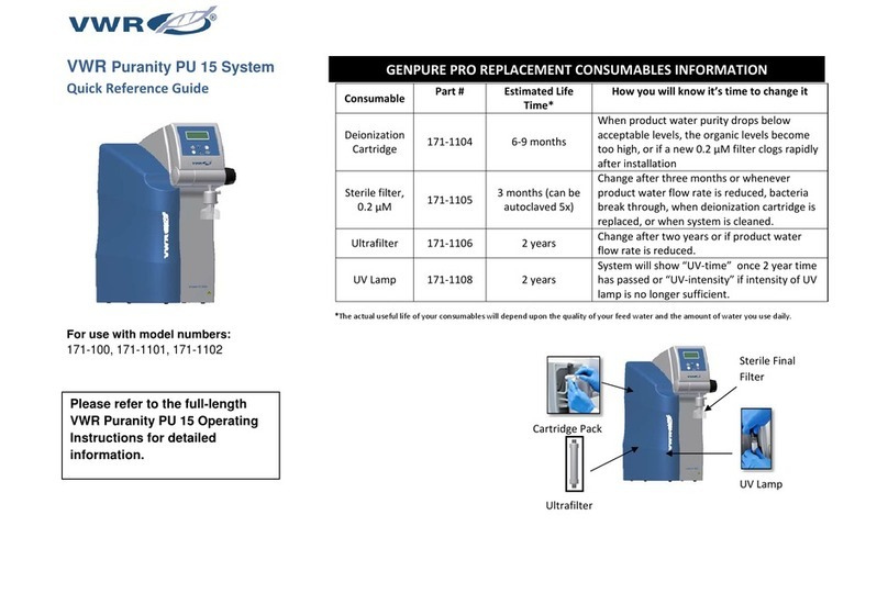
VWR Puranity PU 15 System User manual

i
VWR Puranity PU 15
INSTRUCTION MANUAL
Version: 1
Issued: 18.03.2013

ii
Legal Address of manufacture
Belgium
VWR International bvba
Researchpark Haasrode 2020
Geldenaaksebaan 464
B - 3001 Leuven
Tel.: 016 385 011
Fax: 016 385 385
E-mail:
Country of origin
Germany

iii
Puranity PU 15

iv
Preface
Dear Sir or Madam
In deciding to purchase an ultrapure water system from the Puranity PU 15 series, you have
selected a high-quality product.
Before you start to install and work with your Puranity PU 15 system, please carefully read
the information that is given in these operating instructions on how it is to be installed and
operated.
This is particularly important as we, the manufacturer, cannot accept liability for any damage
occurring as a result of incorrect operation of the system or from use of it for other than the
specified purpose.
Thank you for the confidence you have placed in us.

v
Table of Contents
1. Symbols & conventions .......................................................................... 1
2. Package contents................................................................................... 2
3. Safety information .................................................................................. 3
3.1 Warning ............................................................................................................................. 4
4. Use ......................................................................................................... 5
4.1 Intended use ...................................................................................................................... 5
4.2 Unintended use.................................................................................................................. 5
5. Accessories & spares............................................................................. 6
5.1 Spares ................................................................................................................................ 7
5.2 Accessories ....................................................................................................................... 7
6. Specifications ......................................................................................... 8
7. Describtion of how the systems functions ............................................ 10
7.1 Flow chart for Puranity PU 15.......................................................................................... 10
7.2 Flow chart for Puranity PU 15 UV/UF .............................................................................. 11
7.3 Flow chart for Puranity PU 15 UV.................................................................................... 12
8. Installation ............................................................................................ 13
8.1 Installation area ............................................................................................................... 13
8.2 Installation........................................................................................................................ 14
8.3 Mounting the power pack (voltage supply) ...................................................................... 16
8.4 Wall mounting (option)..................................................................................................... 17
9. Putting the system into operation ......................................................... 18
9.1 Venting the sterile filter .................................................................................................... 18
10. Instruction for use............................................................................... 19
11. The system control .............................................................................. 20
11.1 Menu.............................................................................................................................. 21
11.1.1 Feedwater conductivity ........................................................................................... 21
11.1.2 Ultrapure water limiting value:................................................................................. 21
11.1.3 UV-Lamp operating time and intensity: ................................................................... 22
11.1.4 Filter cartridge operating time counter: ................................................................... 22
11.1.5 Rinsing .................................................................................................................... 22
11.1.6 Disinfection.............................................................................................................. 23
11.1.7 Display of fault storage:........................................................................................... 24
11.1.8 Data print out........................................................................................................... 25
11.1.9 Unlocking the system .............................................................................................. 25

vi
11.2 OEM Menu:.................................................................................................................... 27
11.2.1 Setting the limiting temperature for the system:...................................................... 27
11.2.2 Setting the rinsing time:........................................................................................... 28
11.2.3 Changing the disinfection time: ............................................................................... 28
11.2.4 Setting the interval time for the pump: .................................................................... 28
11.2.5 Setting the interval rinse time:................................................................................. 29
11.2.6 Setting the real-time clock:...................................................................................... 29
11.2.7 Setting the sending interval:.................................................................................... 29
11.2.8 Selecting the language:........................................................................................... 30
11.2.9 Switching units: ....................................................................................................... 30
11.2.10 Switching temperature compensation on/off: ........................................................ 30
12. General maintenance ......................................................................... 31
12.1 Maintenance intervals.................................................................................................... 32
12.2 Change the filter cartridge ............................................................................................. 33
12.3 Disinfection procedure ................................................................................................... 34
12.4 Change the ultrafilter ..................................................................................................... 36
12.5 Change the UV lamp ..................................................................................................... 37
13. Equipment disposal ............................................................................ 38
14. Trouble shooting................................................................................. 39
15.Technical service .............................................................................. 41
16. Warranty............................................................................................. 42
16.1 Compliance with local laws and regulations ................................................................... 42
17. Appendix ............................................................................................ 43
17.1 Terminal assignment ..................................................................................................... 43
17.2 Maintenance record ....................................................................................................... 44

1
1. Symbols & conventions
EU Mark of Conformity
This symbol indicates the presence of high voltage and warns
the user to proceed with caution.
Important operating and/or maintenance instructions! Read the
operating instructions with due care.
Risk of electric shock! Electrical work on the system is only to be
carried out by qualified personnel.
General information! Particularly important notes are marked with
this information sign.
Protective conductor connection
Connect the power supply to an electrical socket with a protective
connection.
The information provided in these operating instructions is only valid for the system which
has the serial number which is to be entered on the front page.
Please enter the serial number* of your Puranity PU 15 system in
the space provided on the front page.
* Read the serial number of your ultrapure water system from the type plate.
For quick and correct service, please include the following information on all inquiries and
replacement parts orders which relate to your system:
- The serial number
- The article number

2
2. Package contents
Ultrapure water systems are carefully controlled and packed prior to dispatch, but damage
could still possibly occur during transport. Carrying the system by hand is always to be by
two people. Do not throw or tip the system.
Examination on receipt
-Check the completeness of the goods received against the delivery note.
Does the packaging show signs of damage?
-Inspect the system for damage.
Complaints
Should damage have occurred to the goods during transport:
-Immediately contact the post, railway or forwarding agent *.
-Save the complete packaging, including the cardboard box, for a possible
inspection of them and/or return shipment of the system.
Packing for return
If possible, use the original box and packaging material.
When these are no longer available, then:
-Protect the system from shock by packing it in a suitable bag or sheet and a
strong cardboard box.
* The time limit for claims is 6 days from the time of receipt of the
goods.
The right to claim for damages ceases when this time has elapsed.

3
3. Safety information
For your own safety, please observe the above safety precautions!
Each system of the Puranity PU 15 series is a modern ultrapure through out water
system, exclusively designed for the purification of tap water of drinking water
quality.
Please do not start to install and operate your system until you have read through
the information given in these operating instructions.
Please note that the manufacturer is freed from all liability when the system is used
for other than the intended purpose and/or is improperly operated.
Lifting and carrying the ultrapure water system, e.g. to the installation location,
should be carried out by two people. To lift it, each takes hold of it under the base
plate at two corners.
The CE-mark is invalidated when constructional changes are made to the system
or foreign products are installed in it.
Protect the system from frost. The temperature at the installation area must be at
least + 2°C.
Observe all general rules and regulations that are valid at the installation location,
including the current accident prevention regulations.
The feedwater pressure must be min. 1 bar and max. 6 bar. An additional pressure
reducer must be installed should it be higher.
According to DIN EN 1717 (for German and Europe), water purification systems
must be equipped with a device that safeguards the tap water against
contamination.
A suitable electric socket must be made available for the system (refer to Technical
Specifications).
The installation area must have a drain floor or a gravity floor with at least
DN(nominal diameter) 50 pipe and which allows free run off. Should no such drain
be available, we recommend the installation of a water watcher (article no. 171-
1126), otherwise the manufacturer will not accept any liability for water damage.(
specifically for Europe)
When the system is to be wall-mounted, please previously check that the wall has a
sufficient load-bearing capacity (refer to Technical Specifications for the weight).
The ultrapure water system only be mounted on a concrete wall or a solid masonry.
The maximum operating temperature of the system is 40°C.

4
If neither a floor drain is not is available, then proceed as follows during longer
system standstills (e.g. long holidays):
Switch the system off (unplug the mains plug).
Shut off the supply of water to the ultrapure water system.
Do not re-start the system with the water supply still in the shut off condition, as the
pump would then suffer damage. The manufacturer will not accept any liability
should this occur. When restarting your system, please open the feedwater to the
ultrapure system and follow our sanitization instructions to put your system into
operation.
When installing the ultrapure water system, ensure that there is sufficient working
room around it for problem-free operation of it as well as for filter replacement,
checking connections etc.
The warranty is valid for a period of 2 years!
Never look directly at a switched-on UV-lamp, because UV light endangers
eyesight!
Never switch the UV-lamp on when is has been taken out of the metal cylinder!
3.1 Warning
Installing the appliance incorrectly, making incorrect settings on it or modifying it can
lead to damage, injury or even death.
Do not put your fingers in socket of electrical connector because a electrical shock
you can have.
Do not swap any electrical parts of the unit when it is on and works, because there is
a danger of electrical shock exist.

5
4. Use
4.1 Intended use
Puranity PU 15 ultrapure water systems are a reaction to actual user needs, the continually
increasing requirements that water of ultrapure quality must fulfill, the increasingly strict
demands resulting from technological advances and the need for user-friendly systems and
complete solutions.
Puranity PU 15 systems have therefore been solely and specifically designed for the
production of ultrapure water which is free of particles, salts and organic compounds and is
sterile filtered.
Application areas
- Analytical methods:
- HPLC ( High Performance Liquid Chromatography )
- IC ( Ion Chromatography )
- ICP ( Inductive Coupled Argon Plasma )
- AAS ( Atomic Absorption Spectrophotometry )
- TOC Analysis ( Total Organic Carbon )
- etc.
- Reagent and solution preparation:
- Cell culture media
- Tissue culture media
Ultraclean washing and rinsing processes in laboratories
4.2 Unintended use
It must be stated according to standard din en iso 12100

6
5. Accessories & spares
Puranity PU 15 ultrapure water system versions with performances of up to 1.5 l/min are
available as follows:
Article no.: 171-1100 Puranity PU 15 Standard (Standard system)
Article no.: 171-1101 Puranity PU 15 UV/UF (Standard system + UV-Photooxidation +
Ultrafiltrationmodule)
Article no.: 171-1102 Puranity PU 15 UV (Standard system + UV-Photooxidation)
(Please check that your system corresponds to the article number given on the delivery
note.)
1x Puranity PU 15 (according to version) Article no. 171-xxxx
together with an assembly kit , consisting of:
Filter cartridge Article no. 171-1104
Sterile filter capsule, 0.2 µm Article no. 171-1105
Feedwater connecting kit, R 3/4" Article no. 171-1127
Rinse water hose, 8 mm o.d., 3 m Article no. 171-1128
Tabletop power pack, 24 VDC Article no. 171-1121
Universal adapter Article no. 171-1129
Universal holder Article no. 171-1130
Connecting cord (rubber connector to nema plug connector) Article no. 171-1131
Connecting cord (rubber connector to british ST plug connector) Article no. 171-1132
Connecting cord (rubber connector to euro plug connector) Article no. 171-1133

7
5.1 Spares
Article designation Article no.
Filter cartridge 171-1104
Sterile filter 171-1105
Ultrafiltration module 171-1106
Circulation pump 171-1107
Replacement UV-lamp
UV-Booster
171-1108
171-1153
Feedwater conductivity measuring cell 171-1109
Ultrapure water conductivity measuring cell
Temperature sensor
171-1177
171-1111
Pressure reducer 171-1112
Check valve 171-1113
Ultrapure water dispensing valve 171-1114
Rinsing solenoid valve 171-1115
Microprocessor control interface 171-1116
Microprocessor control CPU with LCD display 171-1117
Fuseholder for glas tube fuse, 5 x 20mm
Glas tube fuse, 5 x 20mm, 3,15 A, slow
171-1118
171-1119
Table power pack 24V DC 171-1121
5.2 Accessories
Designation Article no.
Disinfection cartridge 171-1183
Disinfection agent, MICRO-Chlor (pack of 12 cans, Europe only) 171-1123
Cleaning Solution, 1 syringe (US-market only) 171-1124
Wall-bracket 171-1125

8
6. Specifications
Demands on the feedwater
Source Potable tap water pretreated by reverse osmosis, ion
exchange or distillation.
Feedwater resistance > 0.20 Mxcm
Free chlorine max. 0.05 ppm
TOC Value max. 50 ppb
Turbidity < 1.0 NTU
Carbon dioxide max. 30 ppm
Silicate max. 2 ppm
Pressure 0.1- 6 bar,
A pressure reducer must be connected in series
when the feedwater pressure is > 6 bar.
Temperature +2 - +35 °C
Product water quality
Standard UV/UF UV
Conductivity µS/cm 0.055 0.055 0.055
Resistance Mxcm at
25°C 18.2 18.2 18.2
RNase
DNase
ng/ml
pg/ul -- --
<0.003
<0.4
TOC ppb 5 - 10 1 - 5 1 - 5
Bacteria CFU/ml < 1 < 1 < 1
Bacterial
endotoxines EU/ml -- 0.001* --
Particles > 0.2 µm per
ml < 1 < 1 < 1
Flow rate L/min 1.5 1.0 1.5
*Contingent on the feedwater and disinfection!
Dimensions
Height: 545 mm
Width: 305 mm
Depth: 300 mm
Weight:
Puranity PU 15 Standard approx. 17 kg
Puranity PU 15 UV/UF approx. 17 kg
Puranity PU 15 UV approx. 17 kg
Water connectors
Feedwater Hose, 8 mm o.d./ R 3/4“
Rinse water Hose, 8 mm o.d.
Cell constants of the measuring cells
Feedwater conductivity 0.16 cm-1
Ultrapure water conductivity 0.01 cm-1

9
Electrical connections / external switched mode power supply
Input voltage AC 100 – 240 V, 50 – 60 Hz, 5 – 3.8 A
Output voltage DC 24 V, 3.8 A
System connection DC 24 V, 80 W
Potential-free contact max. 30V, 2A
Protection Class Class II (external SMPS certified as Class I)
Airborne sound emission
Sound-pressure level 43 dB(A)
Ambient conditions (DIN EN 61010-1 (VDE 0411-1):2011-02)
Usage Indoor rooms
Height Up to 2000 m
Temperature range From 5° C to 40° C
Relative humidity Maximum relative humidity 80 % at temperatures of
up to 31° C, linearly decreasing to 50 % relative
humidity at 40° C
Line-voltage variation Not more than ± 10 % of the line voltage
Transient overvoltages As usually occur in the supply network (overvoltage
category II acc. to IEC 60364-4-44).
Note: The rated level of transient overvoltage is the
withstand impulse voltage acc. to overvoltage
category II of IEC 60364-4-44
Ventilation requirements There are no special requirements with regard to
ventilation.
Degree of pollution 2
Parts which contact water
Pump head Nylon with glass fibre
UV-Lamp High-purity synthetic quartz
UV Housing Stainless steel
Filter cartridge PP
UF Housing Polycarbonate
Rinsing solenoid valve PA
Pressure reducer VA, EPDM
Dispensing valve POM
Conductivity measuring cells PVC, stainless steel
Connections POM
Hoses PE
O-Rings EPDM
Sterile filter PP, PE, PSU

10
7. Describtion of how the systems functions
Puranity PU 15, UV/UF, UV
Tap water that has been pretreated by reverse osmosis, ion exchange or distillation flows
through a pressure reducer and into the ultrapure water system, where the electric
conductivity of it is monitored. A pump forces this feedwater through UV-photooxidation (only
with Puranity PU 15 UV and Puranity PU 15 UV/UF) and a filter cartridge. Following this, the
water is further pumped through an ultrafiltration module (only with Puranity PU 15 UF and
Puranity PU 15 UV/UF) and on past a special conductivity measuring cell equipped with
temperature compensation which continuously measures the conductivity. When treated
water is dispensed, it flows through a sterile filter before exiting from the ultrapure water
outlet. The water inside the system is recirculated at regular time intervals during the
“Interval” mode.
7.1 Flow chart for Puranity PU 15
A-F1 Filter cartridge
A-F2 Sterile filter
A-P1 Circulation pump
QIA 300 Feedwater conductivity
QIA 303 Ultrapure water conductivity
TIA 500 Temperature sensor
V1 Pressure reducer
V2 Check valve
V3 Dispensing valve
V4 Solenoid rinsing valve

11
7.2 Flow chart for Puranity PU 15 UV/UF
A-F1 Filter cartridge
A-F2 Sterile filter
A-F3 Ultrafiltration module
A-P1 Circulation pump
A-UV1 UV-photooxidation
QIA 300 Feedwater conductivity
QIA 303 Ultrapure water conductivity
TIA 500 Temperature sensor
V1 Pressure reducer
V2 Check valve
V3 Dispensing valve
V4 Solenoid rinsing valve

12
7.3 Flow chart for Puranity PU 15 UV
A-F1 Filter cartridge
A-F2 Sterile filter
A-P1 Circulation pump
A-UV1 UV-photooxidation
QIA 300 Feedwater conductivity
QIA 303 Ultrapure water conductivity
TIA 500 Temperature sensor
V1 Pressure reducer
V2 Check valve
V3 Dispensing valve
V4 Solenoid rinsing valve

13
8. Installation
8.1 Installation area
Take the following criteria into consideration when selecting the installation area:
Feedwater pressure, not below 0.1 bar, not above 6 bar.
The feedwater pressure must not be allowed to go above 6 bar. Install an
additional pressure reducer when the feedwater pressure is higher.
Minimum temperature + 2°C.
Level standing surface
A smooth wall is required when the system is to be wall-mounted.
The standing or wall surface must be strong enough to hold the system (for
system weight, see "Technical Specifications")
A gravity drain with a DN(nominal diameter) 50 size (id 38.5 mm) waste pipe is
required.
When no such floor drain is available, install a water watcher (article no.: 171-
1126) to guard against water damage! (specifically for Europe)
Free gravity flow to drain must be ensured!
An electric socket with protective conductor must be available for connection of the
system to the voltage supply (see Technical specifications).
Position the system so that there is no difficulty in separating the
device from the electric mains.
There must be sufficient working space around the system (filter replacement
etc.).
The system must be easy to operate and check.
R 3/4" pre-treated-water connection.

14
8.2 Installation
1) Feedwater connector Hose, 8 mm od
2) Rinse water connector Hose, 8 mm od.
3) Connection power supply 4-pin 24V DC
4) Sterile filter
5) Filter cartridge
Proceed as follows to install and start your Puranity PU 15 ultrapure water system:
Either stand the system on the intended surface or hang it on a wall using the wall-
mount which is available as an accessory.
Press the push-button of the cartridge cover to unlock the cover. Remove the cover.
Remove the stoppers from the filter cartridge (5) which is supplied with the system
and save them for possible return of the spent filter cartridge (only when it is to
carry out waste disposal).
Fit filter cartridge (5) in the free space at the back of the compartment, then plug the
2 quick-connect couplings onto the filter cartridge connections so that they audibly
snap into position.
Use the R3/4" feedwater hose kit to make connection to the feedwater connector
(1).
Position the dirt-trap sieve (from the hose kit) in the 3/4" threaded connector of the
feedwater hose and screw this connector to the water tap which can be turned off.
Swivel display
Push-button of the
cartridge cover
Cartridge cover
Rotary knob for
dispensing Ultrapure
water
Quick connectors filter
cartridge
1
3 2
4
5
Other manuals for Puranity PU 15 System
1
Table of contents
Other VWR Water Filtration System manuals
Popular Water Filtration System manuals by other brands

ACO
ACO Lipumax-P installation guide

Bestway
Bestway 58515 owner's manual

Eriez
Eriez FF4 Installation, operation and maintenance instructions

DH Instruments
DH Instruments 1-2 IN. FILTER KIT instruction sheet

Canature
Canature 475 Pro Series Installation & operation manual

Pontec
Pontec PondoClear Set operating instructions

Eureka Forbes
Eureka Forbes Dr. Aquaguard MAGNA UV user manual

Blue Wave
Blue Wave EASY CLEAN 100 instruction manual

Duro
Duro 6200 SXT Operating and service manual

Everpure
Everpure PBS-400 installation instructions

Clack
Clack T.F.C.-400 Installation, operation & service manual

Formula Air
Formula Air Cyclone FA Maintenance manual