Canature 475 Pro Series User manual

475 PRO SERIES
Reverse Osmosis System
Installation & Operation
Manual
REV. #1 9.18.11
PLEASE READ ALL INSTRUCTIONS BEFORE INSTALLING AND USING THIS SYSTEM
Model
STAGE 1
STAGE 2
STAGE 3
STAGE 4
OUTPUT
475
SEDIMENT
CARBON
TFC RO
MEMBRANE
CARBON
75 GPD
475-BP
SEDIMENT
CARBON
TFC RO
MEMBRANE
CARBON
75 GPD
These drinking water systems are not intended to be used for the treatment of
water that is microbiologically unsafe or of unknown quality.

Your Reverse Osmosis System has been factory tested to
ensure proper operation. The following periodic
maintenance is recommended so your system will provide
years of trouble-free service:
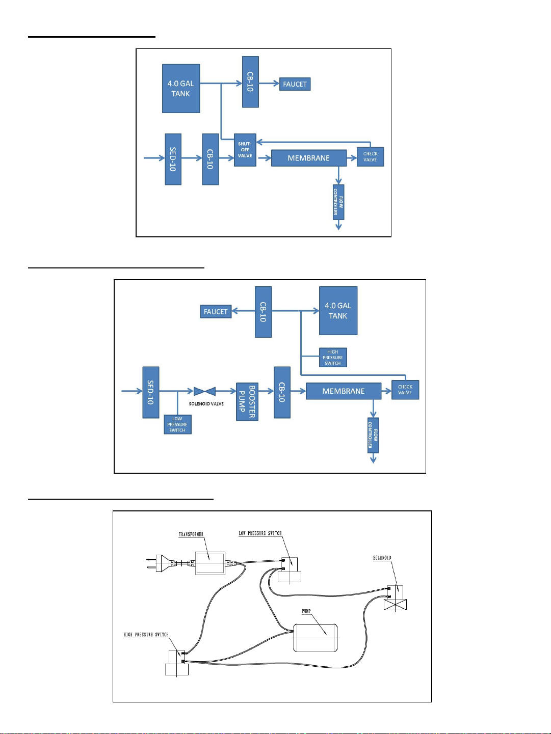
Disposable Filters Change Schedule
Sediment (SED-10) Every 3-6 months
Carbon (CB-10) Every 6-12 months
R/O membrane Every 24-36 months
Components
The following components make up your Reverse Osmosis
Drinking Water System:
1. Pre-filter (Sediment SED-10) removes larger particles
such as sand, silt, and rust.
2. Pre-filter (Carbon COC-10) removes chlorine in the
feed water to protect the reverse osmosis membrane.
3. Reverse Osmosis Membrane reduces dissolved
minerals, metals and salts. During the process,
harmful compounds are separated by the membrane
and the reject water goes to waste (drain).
4. Post-filter (Carbon COC-10) is provided for a final
“polish” to provide great tasting drinking water.
5. Storage tank holds filtered water, ready for use.
6. Automatic shut-off valve senses when the storage
tank is full and closes the water supply to conserve
water.
7. Faucet used to dispense RO water when needed.
8. Feed water valve is connected to the cold water line
to supply water to the RO system.
9. Waste water saddle valve is connected to the drain to
remove reject water from the RO system.
Tools
The following tools may be necessary, depending on each
particular installation:
3/8`` variable speed electric drill; 1/8”, ¼”, ½” bits
Center punch and hammer
Phillips head and flat blade screwdrivers
Adjustable wrench
Teflon tape
Plastic tube cutter
System Location
Your R/O system may be installed under a sink, in a
basement or other location, depending on available space.
Do not install unit where temperatures fall below freezing;
otherwise, damage will result. Connection to an icemaker
should also be considered for optimum performance.
Guidelines for component placement are as follows:
Faucet should be placed near the sink where
drinking/cooking water is normally required. A 2`` flat
surface is required to mount the faucet if an existing hole for
a second faucet is not available. The thickness of the
mounting surface should not exceed 1-1/4``.
Storage tank may be placed where it is convenient, within
ten feet of the faucet. Under the sink or in a nearby cabinet
are excellent choices. If tank is located further than ten feet
from the faucet, use 1/2`` tubing to reduce pressure drop.
Full tanks may weigh more than thirty pounds, so a sturdy
shelf is required.
RO unit may be mounted on either side of the sink, in a
cabinet or heated basement, with nearby access to a
potable, cold line.
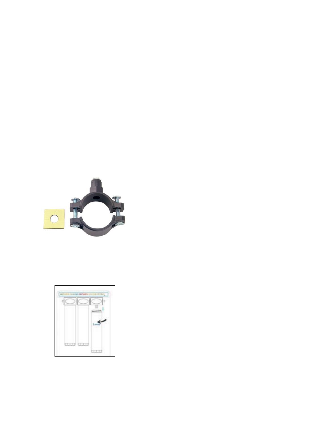
Feed water connection is accomplished with a feed water
adaptor or self-piercing feed water saddle valve. Locate this
assembly as close to the R/O unit as possible. Connect to a
potable, cold water supply line only.
NOTE: Softened water is preferred since it will extend the
life of your R/O membrane.
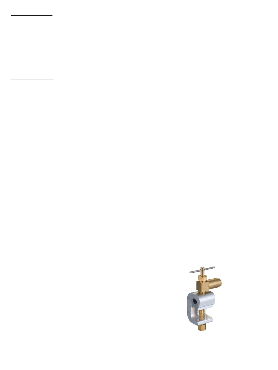
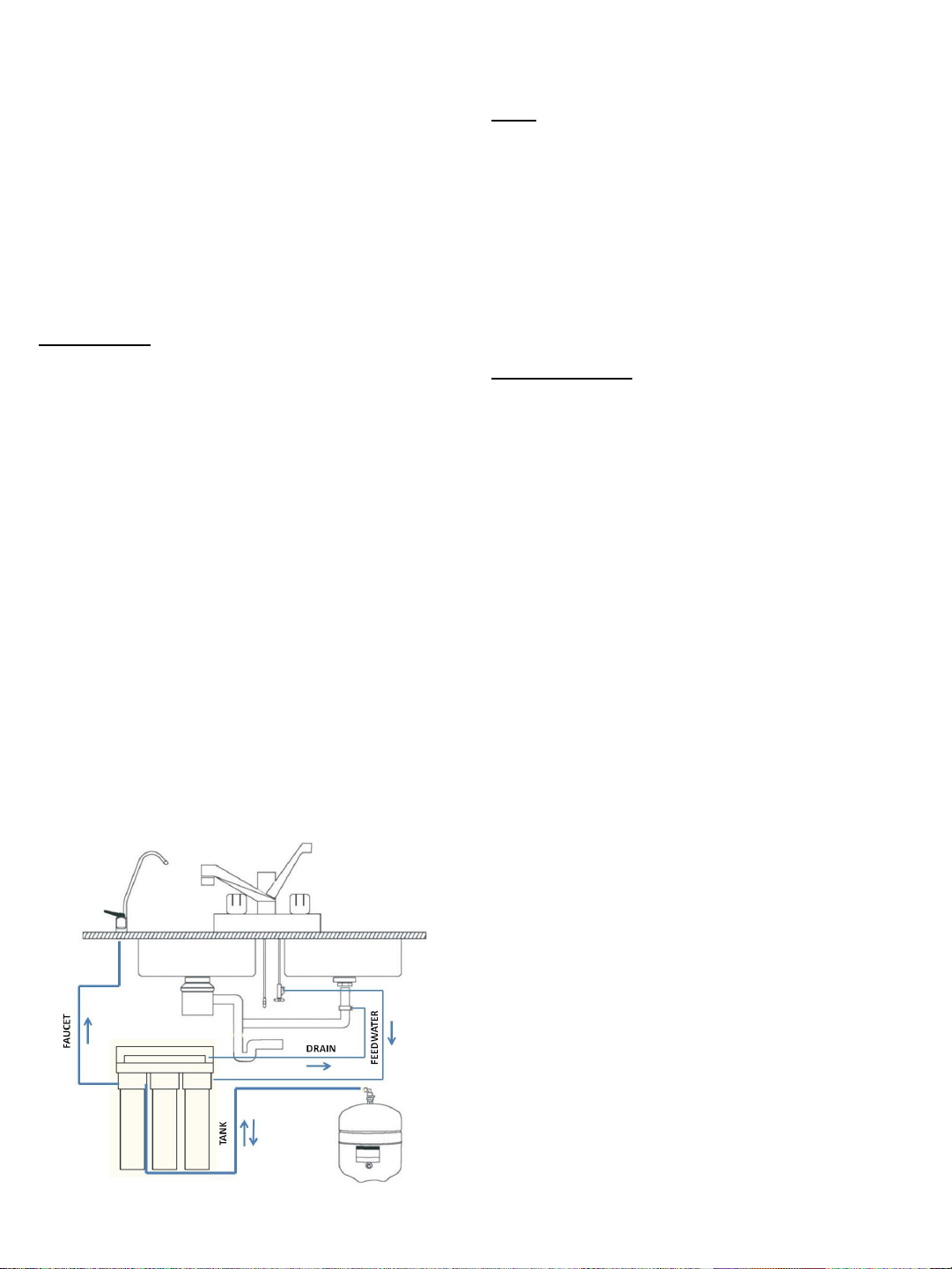
Drain connection is accomplished using a waste water
saddle valve which is designed to fit around a standard 1-
1/2`` OD drain pipe. The drain saddle valve should always be
installed above (before) the trap and on the vertical or
horizontal tailpiece. Refer to Figure 1
NOTE: Some local plumbing codes may require an air gap
drain connection.
Figure 1. Installation Example
#1#2
#3
#4 #5
#7
#8
#9
#6
2
Installation Instructions
Reverse Osmosis Drinking Water System

Site Preparation
Installers may want to speak with customers in advance
and ask them to clean under the sink to save time. If a
basement installation is advisable, check area to
determine if extra fittings or hosing are required. Upon
arrival it is a good idea to check the condition of all
plumbing for potential leaks and advise customer so there
will be no misunderstandings in the event leaks occur.
Unit Preparation
Open shipping carton, remove components and check that
all parts are present.
Installation Steps
All plumbing must be completed in accordance with
provincial/state and local plumbing codes. Some
municipalities may require installation by a licensed
plumber. Check local authority prior to installation.
1. Faucet Installation
If the sink has a sprayer it may be disconnected for faucet
installation. (Installers should discuss this with customers).
A pipe cap or plug will be necessary to seal the sprayer
connection.
The faucet should be positioned so it empties into the sink
and the spout swivels freely for convenience. If sink has a
hole that can accommodate the RO faucet, no drilling Is
required. Proceed with mounting the faucet.
Porcelain, Enamel, Ceramic on Metal or Cast Iron Sinks
For porcelain/enamel sinks marble or granite counter
tops refer to Manufacturer/Supplier for proper drilling
instructions.
Installation procedures for stainless steel sinks
Recommended tools:
Center punch
Variable speed drill
High speed drill bits
Protective gloves & eye protectors
Continued next section top of page.
3
Installation procedures for stainless steel sinks Con’t
To make the faucet mounting hole (if sprayer or second
hole is not used), check below to make sure the drill does
not interfere with anything below the sink. Center punch a
small indent at the desired faucet location. (2`` flat surface
is required, not exceeding 1-1/4`` in thickness). Drill the
1/8”pilot hole. Drill the ½” hole for the faucet shank to fit
through. Clean up sharp edges.
Mounting the Faucet
Disassemble hardware from the threaded nipple, except
for chrome base plates and rubber washers.
Feed the threaded nipple through sink or counter
mounting hole and orient the faucet. From below sink or
counter, assemble the flat washer and hex nut on
threaded nipple and tighten by hand. After checking
faucet orientation, tighten with a wrench until secure.
2. Feed Water Adaptor Valve and Tubing Installation
The self piercing saddle tapping valve which is also
supplied is designed for use with 3/8`` to 1/2`` OD soft
copper supply tubing.
1. Turn off cold water valve from under sink or main
water line valve for whole house.
2. Before installing saddle tapping valve, make sure
piercing lance does not protrude beyond rubber
gasket.
3. Assemble saddle valve on copper tubing.
4. Tighten screw to fasten saddle valve to copper tubing.
5. Connect 1/4`` feed water tubing from the R/O inlet to
the quick connect fitting on feed water adaptor valve.
6. Turn handle clockwise to pierce soft copper tube until
valve is firmly seated. (Valve is closed in this position).
7. Turn on water supply to pressure cold water line and
check for leaks.
Figure 2. Feed Water Saddle Valve

4
3. Drain Saddle Valve Installation
Prior to proceeding it is important to inspect the condition
of drain pipes to make sure they are not thin and frail.
Drain saddle valves are designed to be installed on
standard 1-1/2`` OD drain pipe.
Install drain saddle valve above (and before) the trap
and on the vertical or horizontal tailpiece. Never install a
drain saddle valve close to the outlet of a garbage disposal
or plugging of the RO drain line may result . Refer to
Figure 1.
1. Position half of drain saddle valve with quick connect
fitting at selected location and mark for the opening.
2. Drill ¼`` hole at mark through one side of pipe.
Position both halves of drain saddle on drain pipe so
quick connect opening lines with hole.
3. Secure drain saddle clamp on valve with bolts and nuts
provided. (Do not over tighten and make sure there is
equal space between saddle halves on each side).
4. Filter Cartridge Installation
Install cartridge filters into RO unit. (Also refer to figure 1.)
5. RO Unit Installation
The unit is normally mounted to the right or left sink
cabinet sidewall. To mount the unit, elevate it at least 3``
off the floor, level it and mark the location of mounting
holes needed.
Figure 3. Drain Saddle Valve
Drill holes for mounting screws and install screws, allowing
the mounting bracket slots to slip over them.
NOTE: If the cabinet sidewalls are not solid, unit may sit on
the floor with screws to keep it against the cabinet in a
vertical position.
6. Tubing Connections
With all components in place, complete final tubing
connections using these guidelines:
•Tubing should follow contour of the cabinets
•Cut tubing to desired length using square cuts and
proper cutting device
•Make no sharp bends
•Keep tubing from the unit to the faucet as short as
practical for good flow
Procedure
1. Connect 3/8”tubing from faucet to RO unit.
2. Connect 3/8”tubing from tank to RO unit.
3. Connect ¼” tubing from supply valve to RO unit.
4. Connect ¼” tubing from drain valve to RO unit.
7. System Start-Up
1. Check all connections to be sure they are secure.
2. Turn on feed water valve and check for leaks. (Turn
off and correct leaks if leaks occur).
3. Close faucet and wait a reasonable amount of time to
see if leaks result.
8. Flush System and Check Operation
1. Open faucet handle and allow tank to completely
drain of sanitizing solution. Do not use this water.
NOTE: When tank is empty, faucet will steadily drip.
This is the rate the RO system processes water.
2. Close faucet and re-inspect system for leaks.
3. Allow system to process water for approximately four
hours, at which point tank will be practically full.
4. Open faucet again and allow tank to empty for a
second time. Do not use this water.
5. Wait another four hours to allow tank to re-fill.
NOTE: If no objectionable tastes are noticed after
second tank draining, RO processed water is ready for
use. Otherwise, drain tank and re-fill for a third time.
Figure 4. Filter Installation

Maintenance
Change Filters
Your system contains filters which must be replaced
periodically for proper operation. (Please see Page 2 for
general filter change schedule)
NOTE: Filter cartridges may require changing more
frequently depending on the source water conditions.
In each filter head there is an automatic shut-off device
which allows the filters to be changed without having to
turn off the inlet water supply.
To change filters follow the procedures in figure 5 below.
NOTE: Expect a few drops of water when removing the
filter cartridge.
Change Membrane
Your system contains a reverse osmosis membrane which
should be replaced periodically for proper operation.
(Please see Page 2 for general filter change schedule)
NOTE: RO Membrane may require changing more
frequently depending on the source water conditions.
To change filters follow the procedures below:
1. Turn off water supply by turning feed water saddle
valve clockwise until valve is fully closed.
2. Turn storage tank valve clockwise to close.
3. Open faucet to relieve pressure.
4. Remove quick connect fittings from RO Membrane.
5. Re-connect RO Membrane.
6. Turn water supply back on.
7. Turn storage tank valve to open position.
8. Empty storage tank. Produce an additional full tank of
water and discard it.Normal operation can resume.
5
Figure 5. Filter Installation
Figure 6. RO Membrane
Water Pressure and Temperature
Product water quality and production of RO systems is
dependent on pressure and temperature. Typically, RO
membranes are rated at standard conditions of 77F (25 C)
and 60 psi (4 bar) discharging to atmosphere. In general,
the higher the pressure differential and temperature,
increased quality and quantity of water is produced. These
factors should be considered when sizing RO systems for a
particular application.
Quick Connect Fittings
The 475 PRO Series system utilizes quick-connect fittings.
Proper use of these push-in fittings is shown below. Along
with these fittings, all tubing selected must be of high
quality and must be cut with a plastic tube cutter or sharp
razor with a clean, square cut.
Should a leak occur at a fitting, the cause is generally
defective tubing. To fix a leak, relieve pressure, release
tubing, cut off at least ¼`` from the end (square cut),
reattach the tubing and confirm the connection is leak-
free. Each time a new connection is made, it is advisable
to cut of ¼`` from the end of the tubing using these fittings.
Cut the tube square and remove
burrs and sharp edges. Ensure
that the outside diameter is free
from score marks. For soft or
thin walled plastic tubing we
recommend the use of a tube
insert.
Push the tube into the fitting and
up to the tube stop.
Pull on the tube to check that it
is secure. Test the system
before use.
To disconnect, ensure that the
system is depressurized, push
the collet square against the
fitting. With the collet held in this
position the tube can be
removed.

6
Flow Diagram (No Pump)
Flow Diagram (With Booster Pump
Wiring Diagram (With Booster Pump

7
Trouble Shooting
PROBLEM
CAUSE
SOLUTION
No product water.
1. Water supply is turned off.
1. Turn on feed water.
Not enough product
water.
1. Water supply is blocked.
1. Clear restriction.
2. Filters are plugged.
2. Replace pre-filter cartridge(s).
3. Feedwater valve plugged or closed.
3. Open valve or unclog.
4. No drain flow. Drain flow restrictor
is plugged.
4. Clear or replace Drain Restrictor
Pump not running.
1. Low feed water pressure.
1. Check source water supply.
2. No power supply or loose
connection.
2. Turn on power supply.
3. Transformer burnt out.
3. Repair or replace.
Pump running but system
not producing water.
1. Carbon pre-filter CB-10 plugged.
1. Replace filter cartridge.
2. Inlet solenoid valve not working.
2. Repair or replace solenoid valve.
System does not shut off.
1. High pressure switch not working.
1. Repair or replace high pressure
switch.
Abnormal pump cycling
noise.
1. Pre-filter plugged or low feed water
pressure.
1. Replace filter or adjust or sufficient
feed water.
No water to drain.
1. Plugged drain flow restrictor.
1. Replace drain flow restrictor.
Water has bad taste.
1. Post filter (CB-10) is exhausted.
1. Replace post filter (CB-10)
Leaks
1. Tubing connections not installed
properly.
1. Re-install tubing into fitting.
2. Defective tubing.
2. Cut damage section of tubing and re-
install.
Guarantee
475 PRO systems (excluding cartridge pre-filter, post-filter, and membrane) are warranted to be free from defects in
materials and workmanship under normal use within the operation specifications for a period of two (2) years from
the date of manufacture or date of purchase when verified by a bill of sale.
Canature North America Inc. will replace any part which fails two (2) years from date of manufacture as indicated by
the serial number, provided the failure is due to a defect in material or workmanship. The only exception shall be
when proof of purchase or installation is provided and then the warranty period shall be from the date thereof.
Canature North America Inc. assumes no responsibility for consequential damage, labour or expense incurred as a
result of a defect or for failure to meet the terms of these guarantees because of circumstances beyond its control.
Conditions for Use
WATER SUPPLY
CHLORINATED / NON-CHLORINATED
FEED WATER PRESSURE
35 - 100 PSI
TEMPERATE
40 - 100F
PH
3.0 -11.0
MAX. TDS
2000 MG/L
TURBIDITY
< 1.0 NTU
MAX SILT DENSITY INDEX
<4.0
HARDNESS
< 5 GPG
IRON
<0.1
MANGANSESE
<0.05
HYDROGREN SULFIDE
0.00
This manual suits for next models
2
Table of contents
Other Canature Water Filtration System manuals
Popular Water Filtration System manuals by other brands

Teros
Teros 2S Installation and service manual

Blue Mountain
Blue Mountain RAIN HARVESTING TATS15 Installation and specification guide

DARLEY
DARLEY Versa Fresh Pak manual

Spirotech
Spirotech SPIROTRAP SV3 Installation and operating instructions

A.O. Smith
A.O. Smith AO-US-100-R Replacement manual

Clean Water Systems
Clean Water Systems 2510-SXT Installation & start?up guide