USER’S GUIDE:
OPERATIONS & MAINTENANCE
OPERATION INSTRUCTIONS
MACHINE SETUP PROCEDURES
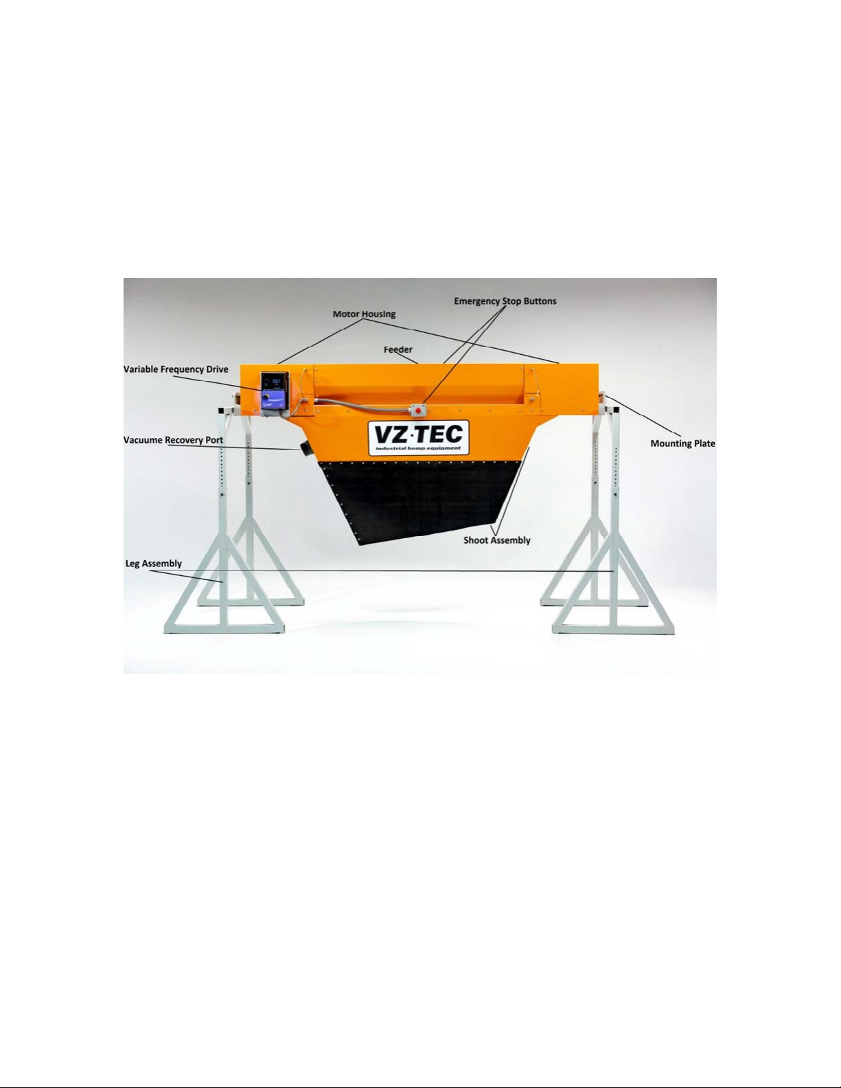
LEG ASSEMBLY
Assemble the leg before hoisting machine, platforms, or putting in place the conveyor belt. The
Easy Bucker employs two separate leg assemblies that allow the machine to set variable height
and to pivot at its center point; these are the center bolt holes on the mounting plate
(Fig 4.1). Bolt holes to either side of the center bolt hole on the mounting plate are to secure
the machine to the desired angle.
Before trying to insert the upper leg into the lower leg makes
sure that the grove on the upper leg and the inner seam on the
lower leg will be on the same plane. Upper leg (Mounting Plate)
inserts into the lower legs (Leg Base) locking into place with
through bolts and nuts. F101.1 and N101.1. Once assembled,
legs should be positioned so that the oset Mounting Plate will
be in direct contact with the machine’s own mounting plate,
once in place.
HOISTING MACHINE
Bring the machine into place by either one of two ways:
1. Forklift: The Easy bucker’s center point is at the center of the
machine, position forks as wide as possible and ender under
the center of the machine. Bring to desired height. Double
check that the legs are at the same height and the center
holes of the machine’s mounting plate and the center hole
of the legs’ mounting plates are in line. Fasten with F102.1
and N102.1 at the center hole of both sides before fastening
the pivoting adjustment hole to the desired angle. NOTE: At
this point the Shoot Assembly and Emergency Stop Buttons
should not be fastened to the machine
2. Engine Hoist: If using an engine hoist to bring the machine
up into place rst place the machine securely onto blocks
or the base of an engine hoist so that ngers and arms
can safely pass under the center point of the machine. At
the center point of the machine use a short strap to wrap
on top of the machine so that the ends of the strap come
underneath the unit and into the area of the shafts inside.
Pass the end of the strap over the shafts and now you bring
in the engine hoist and hook eyelets of straps into the hoist
arm. NOTE: Be sure to test the position of the strap in order
to ensure you have strapped at the point of balance where
the machine can travel parallel to the ground. *At this point
the Shoot Assembly and Emergency Spot Buttons should not
be fastened to the machine.
Fig. 4.1
Fig. 4.2