W.E. Anderson FlotecT V4 series Installation and operating instructions

W.E. ANDERSON DIV., DWYER INSTRUMENTS, INC.
P.O. BOX 358 • MICHIGAN CITY, INDIANA 46360 U.S.A.
Phone: 219/879-8000 www.dwyer-inst.com
Fax: 219/872-9057 e-mail: info@dwyermail.com
Bulletin E-71
Specifications - Installation and Operating Instructions
Vane Operated Flow Switch
SPECIFICATIONS
Service: Gases or liquids compatible with wetted materials.
Wetted Materials: Vane: 316 SS; Body: Brass or 316 SS standard; Magnet
Keeper: 430 SS standard, 316 SS optional; Options: Other materials also
available, consult factory (e.g. PVC, Hastelloy, Nickel, Monel, Titanium).
Temperature Limit: -4 to 275°F (-20 to 135°C) standard, MT high temperature
option 400°F (205°C) [MT option not UL, CSA, AT X or I C x] AT X and I C x
options, ambient temperature -4 to 163°F (-20 to 73°C); Process temperature -4
to 163°F (-20 to 73°C).
Pressure Limit: Brass body 1000 psig (69 bar), 316 SS body 2000 psig (138
bar), optional 5000 psig (345 bar) available with 316 SS body and SPDT switch
only.
Enclosure Rating: Weatherproof and xplosion-proof. Listed with UL and CSA
for Class I, Groups C and D; Class II, Groups , F, and G.
AT X 0518 II 2 G x db IIB T6 Gb -20°C≤Tamb≤73°C.
-20°C≤Process Temp≤73°C.
C-Type Certificate No.: K MA 03 AT X 2383.
AT X Standards: N60079-0: 2012 + A11: 2013; N60079-1: 2014.
I C x Certified: For x db IIB T6 Gb -20°C≤Tamb≤73°C. -20°C≤Process
Temp≤73°C.
I C x Certificate of Conformity: I C X D K 11.0071.
IC x Standards: I C 60079-0: 2011; I C 60079-1: 2014.
Zone I. Also FM approved.
Switch Type: SPDT snap switch standard, DPDT snap switch optional.
Electrical Rating: UL, FM, AT X and I C x models 10A @ 125/250 VAC (V~).
CSA models: 5A @ 125/250 VAC (V~); 5A res., 3A ind. @ 30 VDC (V ). MV
option: 1A @125 VAC (V~); 1A res., .5A ind. @ 30 VDC (V ). MT option: 5A @
125/250 VAC (V~). [MT and MV option not UL, CSA, FM, AT X or I C x].
Electrical Connections: UL and CSA models: 16 AWG, 6˝ (152 mm) long. AT X
or I C x unit: Terminal block.
Conduit Connection: 3/4˝ female NPT or M25 x 1.5 with -BSPT option.
Process Connection: 1-1/2˝ male NPT or 1-1/2˝ male BSPT.
Mounting Orientation: Within 5° of vertical for proper operation. Units for
horizontal installation (vertical pipe with up flow) available.
Set Point Adjustment: For universal vane: five vane combinations.
Weight: 4 lb 8 oz (1.9 kg).
Series
V4
Rugged and reliable the Flotect®V4 flow switch operates automatically to
protect equipment and pipeline systems against damage from reduction or loss of
flow. The V4 is time tested being installed in thousands of pipelines and processing
plants around the world. A unique magnetically actuated switching design gives
superior performance. There are no bellows, springs, or seals to fail. Instead, a free-
swinging vane attracts a magnet within the solid metal switch body, actuating a
snap switch by means of a simple lever arm.
FEATURES
• Leak proof body machined from bar stock
• Choice of custom vane calibrated for your application, Model V4, or field
adjustable multilayer vane, Model V4-2-U (see set point chart on page 4)
• Weatherproof, designed to meet N MA 4
• xplosion-proof (listing included in specifications)
• Installs directly and easily into pipeline with a thredolet, tee, or flange (see
application drawings on page 4)
• Can be used in pipes 1-1/2˝ and up
• lectrical assembly can be easily replaced without removing the unit from
installation so that the process does not have to be shut down
• High pressure rating of 1000 psig (69 bar) with the brass body and 2000 psig (138
bar) with the 316 SS body
APPLICATIONS
• Protects pumps, motors and other equipment against low or no flow
• Controls sequential operation of pumps
• Automatically starts auxiliary pumps and engines
• Stops liquid cooled engines, machines and processing when coolant
flow is interrupted
• Shuts down burner when air flow through heating coil fails
• Controls dampers according to flow
Notes:
• Check all ratings given in the instructions and on the product to make sure that the
product is suitable for your application. Do not exceed electrical ratings, pressure
ratings, or temperature ratings of the product.
• Disconnect power supply before beginning installation to prevent possible
equipment damage or electrical shock.
MAINTENANCE
Inspect and clean wetted parts at regular intervals. The cover should be in place at
all times to protect the internal components from dirt, dust, and weather, and to
maintain hazardous location ratings. Disconnect device from the supply circuit
before opening to prevent ignition of hazardous atmosphere. Repairs to be
conducted by Dwyer Instruments, Inc. Units in need of repair should be returned to
the factory prepaid.
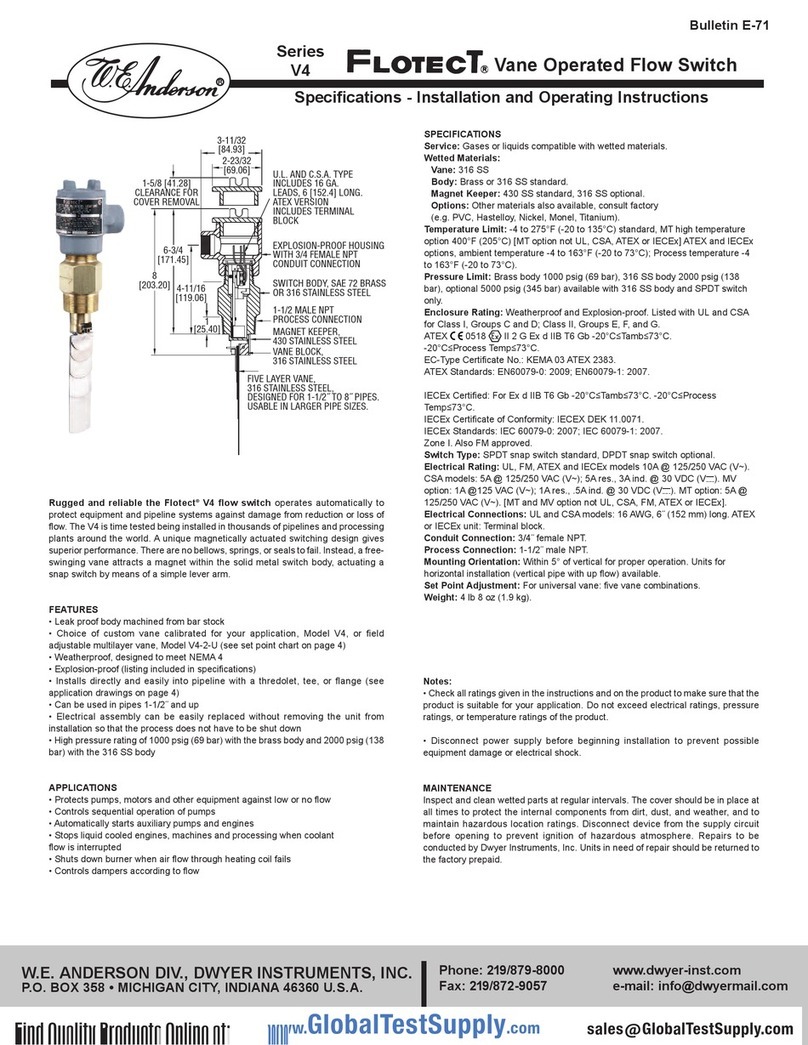
U.L. AND C.S.A. TYPE
INCLUDES 16 GA.
LEADS, 6 [152.4] LONG.
ATEX VERSION
INCLUDES TERMINAL
BLOCK
EXPLOSION-PROOF HOUSING
WITH 3/4 FEMALE NPT
CONDUIT CONNECTION
SWITCH BODY, SAE 72 BRASS
OR 316 STAINLESS STEEL
1-1/2 MALE NPT
PROCESS CONNECTION
MAGNET KEEPER,
430 STAINLESS STEEL
FIVE LAYER VANE,
316 STAINLESS STEEL,
DESIGNED FOR 1-1/2˝ TO 8˝ PIPES.
USABLE IN LARGER PIPE SIZES.
VANE BLOCK,
316 STAINLESS STEEL
3-11/32
[84.93]
2-23/32
[69.06]
1-5/8 [41.28]
CLEARANCE FOR
COVER REMOVAL
8
[203.20]
6-3/4
[171.45]
1
[25.40]
4-11/16
[119.06]

Example
Construction
Construction
Options
Magnet Keeper
Material Options
Vane Material
Options
Body Material
Options
Other
Options
Flange*
Flange Size
Flange Material
Flange Rating
Bushing*
Bushing Size
Bushing Type
Bushing Material
Tee*
Tee Size
Tee with Bushing*
Tee Size
Tee Material
and Type
V4-SS-316-C-F2S1
Brass Body, SPDT Switch
316 SS Body
Type 2 Body Style
DPDT Switch
Universal Vane (Omit for a custom vane)
430 SS (Standard)
Nickel 200
316 SS
316 SS (Standard)
Carpenter 20
Hastelloy B
Hastelloy C
Monel
Brass (Standard)
Carpenter 20
CPVC*
Hastelloy B
Hastelloy C
316 SS (Must also use SS construction selection)
Monel
AT X
1-1/2˝ Female BSPT Process Connection, M25 x 1.5
Conduit Connection
IC x
poxy Coated Housing
Full Swing Vane
Flow Test Report
High Pressure*, 5000 psi (345 bar) (Only with SS body)
Hinged Vane
High Temperature* (See specifications for rating)
Gold Contact Snap Switch* (See specifications for rating)
NAC Heat Treated Body*
Neoprene Boot*
No lectrical Housing*
Socket Weld Connection*
Terminal Block Wire Connections*
Time Delay Relay* (On flow decrease)
Time Delay Relay* (On flow increase)
Vertical Up Flow Applications
Flange Process Connection
2˝
2-1/2˝
3˝
4˝
Carbon Steel
316 SS
Monel
Hastelloy B
Hastelloy C
150#
300#
600#
900#
Bushing Process Connection
2˝
2-1/2˝
4˝
Hex
Flush
Brass
Carbon Steel
316 SS
304 SS
Tee Process Connection
1-1/2˝
Tee with Bushing Process Connection (Both same material)
2˝
3˝
Brass 125 #
Brass 150 #
Brass 250 #
Carbon Steel 2000 #(Only with 2˝ and 3˝)
CPVC SCH 80
316 SS 150 #
PVC SCH 80
V4
V4
SS
SS
2
D
U
3
1
2
3
1
1
2
3
4
5
6
1
2
3
4
5
6
7
C
AT
BSPT
IC
POXY
FSV
FTR
HP
HV
MT
MV
NAC
NB
NH
SW
TBC
TRD
TRI
V
F
F
B
T
TB
2
2
2.5
3
4
1
2
4
1
2
3
S
C
S
M
B
H
H
F
1
1
3
6
9
B
C
S
4
B0
B1
B2
C
CP
S
P
*Options that do not have AT X or I C x.
Attention: Units without the “AT” suffix are not Directive 2014/34/ U (AT X) compliant. These units are not intended for use in potentially
hazardous atmospheres in the U. These units may be C marked for other Directives of the U.

INSTALLATION
1. Remove packing material from switch body-cap and remove tape from magnet
keeper. Adjust vane length if necessary on multi-layer vanes only (see flow
rate charts on next page). Install switch in thredolet previously welded to line.
In some cases, it may be necessary to install the switch in a flange or tee (see
installation drawings on next page). Note: extreme care must be exercised in
welding the fitting to the line so that it is plumb and level.
AD USTMENT OF MULTI-LAYER VANE
Remove only those layers which are too long. Leave the smaller layers to
reinforce the vane. The longest vane fits 6˝ (150 mm) or larger pipe, the
second longest vane fits 4˝ (100mm) pipe, etc. Actuation-Deactuation rates
are shown in the charts on the next page. To remove vane layers, proceed as
follows:
a. Remove the two screws and lockwashers holding the layers together. Do
not lose these special corrosion resistant type 316 stainless steel screws and
lockwashers.
b. Remove the unwanted layers.
c. Resecure the vane with the original two screws and lockwashers.
d. With a hammer, lightly peen the ends of the screws so that they can't back
out.
e. If you lose the screws or lockwashers, don't replace with other parts which
may corrode and break. That will void the warrantee and might cause severe
damage to equipment located downstream of the switch.
Note: Custom vane units have been calibrated at factory to meet
requirements. Do not change.
2. The arrow on the side of the switch must point in the direction of flow.
3. Wiring: UL and CSA units only: thread connecting wires through conduit and
connect. Wire in accordance with local electrical codes.
Black - Common
Blue - N.O.
Red - N.C.
Note: Double pole, double throw switches have dual black, blue and red
leads. These are connected in the same manner as single pole, double throw
switches, as described above.
AT X and I C x Installation Instructions:
Cable Connection
The cable entry device shall be certified in type of explosion protection
flameproof enclosure “d”, suitable for conditions of use and correctly installed.
Cable entry may exceed 70°C. Conductors and cable gland rated ≥95°C shall
be used.
Conduit Connection
An x d certified sealing device such as a conduit seal with setting compound
shall be provided immediately to the entrance of the valve housing. Cable
entry may exceed 70°C. Conductors and cable gland rated ≥95°C shall be
used.
Note: The switch is deactivated and contacts are in normal condition when
there is no flow in the line.
4. Make sure conduit or cable are properly sealed. lectrical components must
be kept free of moisture, including condensation, at all times. CAUTION: To
prevent ignition of hazardous atmosphere, disconnect the device from the
supply circuit before opening. Keep assembly tightly closed when in operation.
Note: AT X and I C X units only: The temperature class is determined by
the maximum ambient and or process temperature. Units are intended to be
used in ambient of -20°C≤Tamb≤73°C. Units may be used in process
temperatures up to 133°C providing the enclosure and switch body
temperature do not exceed 73°C. The standard Temperature Class is T6
Process Temp ≤73°C.
FG
E
C
D
1
2
3
4
5
6
7
8
9
10
8
9
10
4
6
7
3
STANDARD V4 CENELEC V4
PROCESS CONNECTION
1-1/2 MALE NPT
3-11/32
[84.93]
2-23/32
[69.06]
1-5/8 [41.28]
CLEARANCE FOR
COVER REMOVAL
1
[25.40]
AB
Ref #
1
2
3
4
5
6
7
8
9
10
Standard V4
N/A
N/A
xplosion-proof housing with 3/4˝
female NPT conduit connection.
16 AWG, 6˝ (152 mm) long.
Internal
Magnet arm and switch assembly.
Switch body of SA 72 Brass or
316 SS.
Five layer vane, 316 Stainless
Steel, Designed for 1/2˝ to 8˝
pipes. Usable in larger pipe sizes.
Magnet keeper of 430 Stainless
Steel.
Vane block of 316 Stainless Steel.
ATEX/IECEx unit
Cover lock.
xternal ground.
xplosion-proof housing with 3/4˝
female NPT conduit connection.
Terminal Block
Internal ground.
Magnet arm and switch assembly.
Switch body of SA 72 Brass or
316 Stainless Steel.
Five layer vane, 316 Stainless
Steel, Designed for 1/2˝ to 8˝ pipes.
Usable in larger pipe sizes.
Magnet keeper of 430 Stainless
Steel.
Vane block of 316 Stainless Steel.
Dim
A
B
C
D
F
G
V4 in(mm)
8-3/16 (207.96)
6 (152.40)
4-11/16 (119.06)
1 (25.40)
1-5/16 (33.34)
7/8 (22.23)
11/16 (17.46)
V4-2 in(mm)
8 (203.20)
6-3/4 (171.45)
3-15/16 (100.01)
1-3/4 (44.45)
9/16 (14.30)
11/16 (17.63)
1/2 (12.70)
AT X/I C x unit
5. For units supplied with both internal ground and external bonding terminals, the
ground screw inside the housing must be used to ground the control. The external
bonding screw is for supplementary bonding when allowed or required by local
code. When external bonding conductor is required, conductor must be wrapped a
minimum of 180° about the external bonding screw. See below.
FRONT VIEW DETAIL SIDE VIEW DETAIL
CLAMP
SCREW
LOCKWASHER CONDUCTOR
Standard V4
TERMINAL CONNECTIONS SPDT TERMINAL CONNECTIONS DPDT

Actuation rates are based on cold water at a specific gravity of 1.0. For fluids of different specific gravity, actuation rates may be approximated by
dividing the rate shown by the square root of the specific gravity.
Actuation rates are based on air at standard conditions. For gases at other pressures, temperatures, or specific gravities, consult factory for
equivalent flow approximations.
VANE
LAYERS
1
1&2
1,2,&3
1,2,3,&4
1,2,3,4,&5
1.5˝ PIPE
7-3
26.67-11.67
2˝ PIPE
15-8
56.7-30
7-4
26.7-15
3˝ PIPE
45-22
167-83.3
23-14
86.7-53.3
11-7
41.7-26.7
4˝ PIPE
95-40
367-150
50-35
190-132
27-19
102-71.7
17-12
65-45
6˝ PIPE
210-120
800-450
130-90
500-333
80-60
300-233
60-45
233-167
40-30
152-113
8˝ PIPE
375-175
1417-667
230-150
867-567
160-115
600-433
120-90
450-333
80-65
300-250
10˝ PIPE
600-300
2267-1133
450-250
1700-950
300-180
1133-683
230-150
867-567
135-100
517-383
12˝ PIPE
900-450
3400-1700
650-350
2467-1317
450-275
1700-1033
310-200
1167-750
200-140
750-533
20˝ PIPE
2400-1200
9083-4550
1800-1000
6817-3783
1200-700
4550-2650
850-550
3217-2083
575-400
2183-1517
18˝ PIPE
2000-1000
7567-3783
1450-800
5483-3033
1000-600
3783-2267
700-450
2650-1700
460-325
1733-1233
16˝ PIPE
1400-800
5300-3033
1200-650
4550-2467
750-450
2750-2083
550-360
2083-1367
360-250
1367-950
14˝ PIPE
1200-600
4550-2267
900-500
3400-1900
600-350
2267-1317
430-280
1633-1067
290-200
1100-750
APPROXIMATE ACTUATION/DEACTUATION FLOW RATES FOR COLD WATER.
UPPER FIGURES IN GPM. LOWER FIGURES IN
LPM
VANE
LAYERS
1
1&2
1,2,&3
1,2,3,&4
1,2,3,4,&5
1.5˝ PIPE
32-17
15-8
2˝ PIPE
65-32
30-20
23-13
10-6
3˝ PIPE
210-105
100-50
120-70
60-30
60-48
30-20
4˝ PIPE
400-200
190-90
195-140
90-70
135-100
60-50
65-50
30-20
6˝ PIPE
950-475
450-220
550-375
260-180
375-265
180-130
260-200
120-90
130-100
60-50
8˝ PIPE
1550-850
730-400
1100-700
520-330
725-500
340-240
500-400
240-190
310-250
150-120
10˝ PIPE
2400-1300
1100-600
1850-1200
870-570
1200-850
570-400
875-700
410-330
650-525
310-250
12˝ PIPE
3450-1900
1600-900
2700-1750
1300-800
1850-1300
870-610
1250-1000
590-470
1000-800
470-380
20˝ PIPE
10000-5500
4700-2600
7400-4800
3500-2300
5300-3700
2500-1700
3900-3100
1800-1500
3550-2850
1700-1300
18˝ PIPE
8000-4400
3800-2100
6000-3900
2800-1800
4300-3000
2000-1400
3100-2500
1500-1200
2800-2250
1300-1100
16˝ PIPE
6400-3500
3000-1700
4800-3100
2300-1500
3350-2350
1600-1100
2500-2000
1200-900
2200-1750
1040-830
14˝ PIPE
4700-2600
2200-1200
3400-2200
1600-1000
2600-1800
1200-800
1900-1500
900-710
1600-1250
760-590
APPROXIMATE ACTUATION/DEACTUATION FLOW RATES FOR AIR.
UPPER FIGURES IN SCFM. LOWER FIGURES IN
LPS
Values shown in both charts are nominal. If normal flows exceed actuation rates by less than 10%, custom vanes are recommended.
Figures are based on standard vertical installation in a 1-1/2" thredolet in a horizontal run of pipe.
V4 Universal Vane Flow Charts
APPLICATION DRAWINGS FOR FLOTECT®AUTOMATIC FLOW SWITCHES
Standard Installation 2-1/2˝ Thredolet Installation
1-1/2˝ X 1-1/2˝ X 1-1/2˝
Tee Installation
2˝ X 2˝ X 2˝
Tee Installation
Flange Installation
W.E. ANDERSON DIV., DWYER INSTRUMENTS, INC.
P.O. BOX 358 • MICHIGAN CITY, INDIANA 46360 U.S.A.
Phone: 219/879-8000 www.dwyer-inst.com
Fax: 219/872-9057 e-mail: info@dwyermail.com

Bulletin E-71
Betriebsanleitung
Durchflußwächter
TECHNISCHE DATEN
Medium: Flüssigkeiten, kompatibel zu den mediumberührenden Teilen.
Mediumberührende Teile:
Schwimer und Arm: 316 delstahl.
Körper: Messing oder 316 delstahl.
Magnethalter: 430 delstahl Standard, 316 delstahl oder Nickel
optional.
Temperaurbereich: -20°C bis 135°C Standard, MT Version bis 205°C
[MT-Option nicht möglich bei UL, CSA, AT X und I C x]. Optionen mit
AT X-, I C x- oder Schutz: Umgebungstemperatur -20 bis 73°C;
Prozesstemperatur -20 bis 73°C.
Druckbereich: Messingkörper: 69 bar, 316 delstahlkörper: 138 bar,
optional bis 345 bar nur verfügbar mit 316 delstahlkörper und 1 x
SPDT.
Gehäuse: Wettergeschützt und xplosionsgeschützt. Listed mit UL
andCSA für Class I, Groups C and D; Class II, Groups , F, and G.
AT X 0518 II 2 G x db IIB T6 Gb -20°C≤Tamb≤73°C.
-20°C≤Prozesstemp ≤73°C.
C-Zertifikat Nr.: K MA 03 AT X 2383.
AT X-Normen: N60079-0: 2012 + A11: 2013; N60079-1: 2014.
I C x-genehmigt: für x db IIB T6 Gb -20°C ≤Tamb ≤73°C.
-20°C≤Prozesstemp ≤73°C.
I C x-Konformitätszertifikat: I C x D K 11.0071 oder M25 x 1,5 mit -
BSPT-Option.
I C x-Normen: I C 60079-0: 2011; I C 60079-1: 2014 oder 1-1/2˝
(47,8 mm) Stecker BSPT.
Mikroschalter: SPDT Standard, DPDT optional.
Schaltleistung: Modelle UL, FM, AT X und I C x: 10A @125/250
VAC (V~). CSA Modelle: 5A @ 125/250 VAC (V~); 5A res., 3A ind. @
30 VDC (V ). MV Option: .1A @ 125 VAC (V~). MT option: 5A
@125/250 VAC (V~). [MT- und MV-Option nicht möglich bei UL, CSA,
FM, AT X und I C x].
Elektrische Anschlüsse: UL und CSA Modelle: 16 AWG, 152 mm
lang, AT X und I C x Ausführung: Klemmleiste.
Kabeleingang: 3/4“ NPTF ou M25 x 1,5 avec BSPT en option.
Prozessanschluss: 1-1/2“ NPTM ou filetage mâle BSPT 1 à 1/2 po
(2,54 à 1,27 cm).
Montagerichtung: Innerhalb 5° zur Vertikalen, Optional Geräte für
horizontalen inbau.
Gewicht: 2,07 kg.
Schaltpunkteinstellung: mit Standardpaddel: Kombination aus fünf
Schichten.
Reihe
V4
Der robuste und zuverlässige Durchflußwächter der Reihe V4
schützt Geräte und Rohrsysteme vor Schäden durch Verringerung oder
fehlendem Durchfluß. Der V4 wurde schon in Tausenden von
Rohrleitungen und Prozessfirmen eingesetzt. Der Wächter basiert auf
einem magnetischen Prinzip. s gibt keine Kolben, Federn oder
Dichtungen, die ausgetauscht werden müssten. Das frei schwingende
Paddel aktiviert einen Magneten innerhalb des soliden metallischen
Körpers, der wiederum einen Mikroschalter auslöst.
HAUPTMERKMALE
• Leckagedichter Körper
• ine Auswahl an kundenspezifischen Paddeln, Modell V4 ist
einstellbar vom Kunden durch mehrschichtiges Paddel, Modell V4-2-U
(siehe Schaltpunkteinstellung)
• Wettergeschütztes Gehäuse, gemäß N MA4
• x-geschützt (siehe Spezifikationen)
• infache und direkte Montage mittels Anschlußgewinde, T-Stück oder
Flanschen (siehe Abb.)
• insatz in Rohren von 36 mm und größer
• Die lektrik kann einfach ausgetauscht werden, ohne den Wächter
vom Prozess zu entfernen, so dass dieser nicht gestoppt werden muss
• Hoher Druckbereich: 69 bar mit Messingkörper, 138 bar mit 316
delstahlkörper
ANWENDUNGEN
• Schützt Pumpen, Motoren oder andere Geräte bei zu niedrigem oder
keinem Durchfluß
• Steuert sequenziellen Betrieb von Pumpen
• Startet automatisch Hilfspumpen und Motoren ein
• Schaltet flüssigkeitsgekühlte Maschinen, Motoren oder Prozesse ab,
wenn der Durchfluß des Kühlungsmittels unterbrochen ist
• Schaltet Brenner ab, wenn die Luftzufuhr durch die Heizspulen defekt
ist
Bemerkungen:
• Prüfen Sie die elektrischen Instruktionen und gehen Sie sicher,
dass das Gerät für die Anwendung geeignet ist. Überschreiten
Sie auf keinen Fall die angegebenen Schaltleistungen, Druck-
und Temperaturbereiche die für dieses Produkt angegebenen
Spezifikationen.
• Lösen Sie die Spannungsversorgung, bevor Sie die elektrischen
Anschlüsse verbinden, um eventuelle Schäden zu vermeiden.
WARTUNG:
Püfen und Reinigen Sie die mediumberührenden Teile regelmässig. Der
Gehäusedeckel sollte immer geschlossen bleiben, um die internen
Komponenten frei von Schmutz und Staub zu halten. Unterbrechen Sie
die Spannungsversorgung in explosionsgefährdeten Umgebungen,
bevor Sie das Gerät öffnen. Reparaturen sollten durch Dwyer
Instruments, Inc. ausgeführt werden.
W.E. ANDERSON DIV., DWYER INSTRUMENTS, INC.
P.O. BOX 358 • MICHIGAN CITY, INDIANA 46360 U.S.A.
Phone: 219/879-8000 www.dwyer-inst.com
Fax: 219/872-9057 e-mail: info@dwyermail.com
U.L. AND C.S.A. TYPEN
ENTHALTEN KABEL
152,4 MM LANG
ATEX VERSION
BEINAL TET KLEMMLEISTE
EX-GESCHUETZTES GEHAEUSE
MIT 3/4 ANSCHLUSS
UNTERES GEHAEUSE AUS
MESSING ODER 316 EDELSTAHL
1-1/2 NPT
MAGNETHALTER 430 EDELSTAHL
5-SCHICHTEN PADDEL ROHRGROESSEN
VON 38,1 MM BIS 203,2 MM EINSETZBAR,
AUCH IN ANDEREN GROESSEN MOEGLICH
PADDEL U. PADDELBLOCK
316 EDELSTAHL
3-11/32
[84.93]
2-23/32
[69.06]
1-5/8 [41.28]
RAUM FUER ABNAHME
DES DECKELS
8
[203.20]
6-3/4
[171.45]
1
[25.40]
4-11/16
[119.06]

*Optionen ohne AT X- oder I C x-Schutz
Achtung:Geraete ohne -AT suffix sind nicht nach ATEX zertifiziert und duerfen nicht in explosionsgefaehrdeten Umgebungen eingesetzt werden.
Beispiel
Konstruktion
Konstruktions-
Optionen
Magnethalterung
Material Optionen
Paddelmaterial
Optionen
Gehaeusematerial
Optionen
Andere
Optionen
Flansche*
Flanschgroesse
Flanschmaterial
Flanschrate
Muffe*
Muffengroesse
Muffentyp
Muffenmaterial
T-Stueck*
T-Stueckgroesse
T-Stueck mit
Muffe*
T-Stueck
T-Stueck Material
und Typ
V4-SS-316-C-F2S1
Messingkoerper, SPDT Schalter
316 delstahlkoerper
Type 2 Koerperstil
DPDT Schalter
Universal Paddel nach Kundenwunsch
430 delstahl (Standard)
Nickel 200
316 delstahl
316 delstahl (Standard)
Carpenter 20
Hastelloy B
Hastelloy C
Monel
Messing(Standard)
Carpenter 20
CPVC*
Hastelloy B
Hastelloy C
316 delstahl (muss auch die anderen als delstahl haben
Monel
AT X
1-1/2˝ (47,8 mm) Buchse BSPT Prozessanschluss, M25 x 1,5 Leerrohranschluss
I C x
poxy beschichtetes Gehaeuse
Full Swing Vane
Flow Test Report
Hochdruck*, 5000 psi (345 bar) (Nur mit delstahlkoerper)
Haengendes Paddel
Hoch - Temperature*
Gold Kontakte
NAC Heat Treated Koerper*
Neoprene Schutz*
Kein elektrisches Gehaeuse*
geschweisste Verbindungen*
Klemmleiste*
Zeitverzoegerungsrelais* (steigend)
Zeitverzoegerungsrelais* (fallend)
Vertikale Montage
Flanschanschluss
2˝
2-1/2˝
3˝
4˝
Stahl
316 delstahl
Monel
Hastelloy B
Hastelloy C
150#
300#
600#
900#
Muffenanschluss
2˝
2-1/2˝
4˝
Hex
Flush
Messing
Stahl
316 delstahl
304 delstahl
T-Stueck Anschluss
1-1/2˝
T-Stueck mit Muffe
2˝
3˝
Messing 125 #
Messing 150 #
Messing 250 #
Stahl 200D #(Nur mit 2˝ und 3˝)
CPVC SCH 80
316 delstahl 150 #
PVC SCH 80
V4
V4
SS
SS
2
D
U
3
1
2
3
1
1
2
3
4
5
6
1
2
3
4
5
6
7
C
AT
BSPT
I C
POXY
FSV
FTR
HP
HV
MT
MV
NAC
NB
NH
SW
TBC
TRD
TRI
V
F
F
B
T
TB
2
2
2.5
3
4
1
2
4
1
2
3
S
C
S
M
B
H
H
F
1
1
3
6
9
B
C
S
4
B0
B1
B2
C
CP
S
P

INSTALLATION
1. ntfernen Sie das Verpackungsmaterial und das Klebeband von der
Magnethalterung. Prüfen Sie die Länge des Paddels und stellen die
Länge auf Ihre Anwendung ein. Installieren Sie den Schalter in das
Schraubteil, dass vorher am Rohr eingeschweisst wurde. Prüfen Sie
vorher noch die Verschraubungen am Paddel In manchen Fällen ist
es notwendig den Durchflußwächter mittels eins T-Stückes oder
Flansches zu befestigen. s muss sehr sorgfältig darauf geachtet
werden, dass beim Schweissen der Anschlüsse, diese sehr fest
sitzen.
EINSTELLUNG DER VERSCHIEDENEN PADDELLÄNGEN
ntfernen Sie die Paddel, die zu lang sind. Lassen Sie alle kürz-
eren Paddel am Schalter, um die gesamte inrichtung zu ver-
stärken. Das längste Paddel passt in einen Rohrdurchmesser von
150 mm oder größer, das Zweitlängste in ein Rohr mit 100 mm
Durchmesser, usw. Die in- und Ausschaltpunkte entnehmen Sie
der beigefügten Tabelle. Um die Paddel zu entfernen gehen Sie
wie folgt vor:
a. ntfernen Sie die zwei Schrauben und Unterlegscheiben, die
Paddel zusammenhalten. Verlieren Sie auf keinen Fall
diese Schrauben.
b. nfernen Sie nun die nicht benötigten Paddel
c. Befestigen Sie die anderen Paddel wieder mit den zwei
Schrauben.
d. Schlagen Sie mit einem Hammer auf die nden der beiden
Schrauben, so dass sich diese nicht mehr lösen können.
e. Wenn Sie die Schrauben oder Unterlegscheiben verlieren,
ersetzten Sie diese nicht durch Schrauben, die in dem ver-
wendeten Medium korrodieren können. Dadurch verlieren
Sie die Garantie des Gerätes.
Bemerkung: Kundenspezifische Paddellängen sind direkt auf die
Kundenanwendung kalibriert worden. Ändern Sie diese nicht mehr.
2. Der Pfeil auf der Seite des Durchflußwächters muss in Richtung
Durchfluß zeigen.
3. Verdrahtung: UL und CSA Geräte: Führen Sie die
Verbindungsdrähte durch die Durchführung und schliessen diese
wie folgt an:
Schwarz Gemeinsamer Pol
Blau stromlos offen
Rot stromlos geschlossen
Bemerkung: DPDT Mikroschalter haben jeweils zwei schwarze,
blaue und rote Drähte. Diese werden in der gleichen Weise
angeschlossen wie bei einem SPDT Schalter.
Montageanleitung für AT X und I C x
Kabelanschluss
Das Kabeleingangsgerät muss in der Kategorie " xplosionsschutz"
als feuersicheres Gehäuse der Klasse D zugelassen sein, für die
insatzbedingungen geeignet sein und korrekt installiert werden.
Die Kabeleingangstemperatur kann über 70° C betragen. s sind
Anschlüsse und Kabelverschraubungen für ≥ 95°C zu verwenden.
Gehäuseverschraubung
Am ingang des Ventilgehäuses ist umgehend eine
Dichtungsvorrichtung mit x-d-Zertifizierung wie beispielsweise ein
Kabelschutzrohr mit Justierung anzubringen. Die
Kabeleingangstemperatur kann über 70° C betragen. s sind
Anschlüsse und Kabelverschraubungen für ≥ 95°C zu verwenden.
Bemerkung: Der Wächter ist deaktiviert und die Kontakte sind in
normaler Schaltung, wenn sich die Flüssigkeit unterhalb des
Schwimers befindet.
4. Prüfen Sie, dass die Gehäuseverschraubungen und Kabel
entsprechend abgedichtet sind. Alle elektrischen Komponenten
müssen öl- und fettrei sein, wie auch frei von Kondensationsfeuchte.
ACHTUNG: Um Zündfunken explosionsgefährdeter Umgebung zu
verhindern, unterbrechen Sie die Spannungsversorgung, bevor Sie
den Füllstandswächter öffnen. Halten Sie das Gerät beim Arbeiten
immer geschlossen.
HINW IS: nur für AT X-, und I C x-Geräte: Die Temperaturklasse
richtet sich entweder nach der max. Umgebungstemperatur oder der
Prozesstemperatur. Die Geräte sind für eine Umgebungstemperatur
von -20 °C < Tamb < 73 °C bestimmt. Die Instrumente können bis zu
einer Prozesstemperatur von 133 °C eingesetzt werden,
vorausgesetzt das Gehäuse und der Schaltkörper erreichen keine
Temperaturen über 73°C. Bei einer Prozesstemperatur von <73°C
lautet die Standardtemperaturklasse T6.
Ref #
1
2
3
4
5
6
7
8
9
10
Standard V4
N/A
N/A
xplosionsgeschuetztes Geh.
3/4˝ NPTF Anschluss-
verbindung
16 AWG, 6˝ (152 mm) long.
Intern
Magnetarm und Schalter
Gehaeuse aus Messing oder
316 delstahl
5-lagiges Paddel, 316 delstahl
fuer 1/2 bis 8 Rohrdurchmesser,
auch fuer groessere Rohre
geeignet
Magnethalter aus 430 delstahl
Paddelblock aus 316 delstahl
ATEX-/IECEx-Geräte
Deckelschloss
xterne rdung
xplosionsgeschuetztes Geh.
3/4˝ NPTF Anschluss-
verbindung
Klemmleiste
Interne rdung
Magnetarm und Schalter
Gehaeuse aus Messing oder 316
delstahl
5-lagiges Paddel, 316
delstahl fuer 1/2 bis 8
Rohrdurchmesser, auch fuer
groessere Rohre geeignet
Magnethalter aus 430 delstahl
Paddelblock aus 316 delstahl
Abmess.
A
B
C
D
F
G
V4 in(mm)
8-3/16 (207.96)
6 (152.40)
4-11/16 (119.06)
1 (25.40)
1-5/16 (33.34)
7/8 (22.23)
11/16 (17.46)
V4-2 in(mm)
8 (203.20)
6-3/4 (171.45)
3-15/16 (100.01)
1-3/4 (44.45)
9/16 (14.30)
11/16 (17.63)
1/2 (12.70)
FRONT VIEW DETAIL SIDE VIEW DETAIL
CLAMP
SCREW
LOCKWASHER CONDUCTOR
Federring
Schraube
Leiter
Seitenansicht
Klemme
Vorderansicht
5. Bei Geräten mit interner rdungsschraube und externer
Verbindungsschraube muss die innere rdungsschraube zur rdung
des Signals verwendet werden. Die externe Verbindungsschraube dient
zur zusätzlichen rdung, falls von örtlichen Regularien erlaubt oder
erfordert. Ist ein externer Verbindungsleiter erforderlich, muss der Leiter
mindestens 180 ° um die externe Verbindungsschraube gewickelt sein.
Siehe unten.
TERMINAL CONNECTIONS SPDT TERMINAL CONNECTIONS DPDT
FG
E
C
D
1
2
3
4
5
6
7
8
9
10
8
9
10
4
6
7
3
STANDARD V4 CENELEC V4
1-1/2 NPTM
PROZESSANSCHLUSS
3-11/32
[84.93]
2-23/32
[69.06]
1-5/8 [41.28]
RAUM FUER ABNAHME
DES DECKELS
1
[25.40]
AB
AT X-/I C x-Geräte
Standard V4

Actuation rates are based on cold water at a specific gravity of 1.0. For fluids of different specific gravity, actuation rates may be approximated by dividing the rate shown by the square root of the
specific gravity.
Actuation rates are based on air at standard conditions. For gases at other pressures, temperatures, or specific gravities, consult factory for equivalent flow approximations.
VANE
LAYERS
1
1&2
1,2,&3
1,2,3,&4
1,2,3,4,
&5
1.5"PIPE
7-3
26.67-11.67
2"PIPE
15-8
56.7-30
7-4
26.7-15
3"PIPE
45-22
167-83.3
23-14
86.7-53.3
11-7
41.7-26.7
4"PIPE
95-40
367-150
50-35
190-132
27-19
102-71.7
17-12
65-45
6"PIPE
210-120
800-450
130-90
500-333
80-60
300-233
60-45
233-167
40-30
152-113
8"PIPE
375-175
1417-667
230-150
867-567
160-115
600-433
120-90
450-333
80-65
300-250
10"PIPE
600-300
2267-1133
450-250
1700-950
300-180
1133-683
230-150
867-567
135-100
517-383
12"PIPE
900-450
3400-1700
650-350
2467-1317
450-275
1700-1033
310-200
1167-750
200-140
750-533
20"PIPE
2400-1200
9083-4550
1800-1000
6817-3783
1200-700
4550-2650
850-550
3217-2083
575-400
2183-1517
18"PIPE
2000-1000
7567-3783
1450-800
5483-3033
1000-600
3783-2267
700-450
2650-1700
460-325
1733-1233
16"PIPE
1400-800
5300-3033
1200-650
4550-2467
750-450
2750-2083
550-360
2083-1367
360-250
1367-950
14"PIPE
1200-600
4550-2267
900-500
3400-1900
600-350
2267-1317
430-280
1633-1067
290-200
1100-750
APPROXIMATE ACTUATION/DEACTUATION FLOW RATES FOR COLD WATER.
UPPER FIGURES IN GPM. LOWER FIGURES IN
LPM
VANE
LAYERS
1
1&2
1,2,&3
1,2,3,&4
1,2,3,4,
&5
1.5"PIPE
32-17
15-8
2"PIPE
65-32
30-20
23-13
10-6
3"PIPE
210-105
100-50
120-70
60-30
60-48
30-20
4"PIPE
400-200
190-90
195-140
90-70
135-100
60-50
65-50
30-20
6"PIPE
950-475
450-220
550-375
260-180
375-265
180-130
260-200
120-90
130-100
60-50
8"PIPE
1550-850
730-400
1100-700
520-330
725-500
340-240
500-400
240-190
310-250
150-120
10"PIPE
2400-1300
1100-600
1850-1200
870-570
1200-850
570-400
875-700
410-330
650-525
310-250
12"PIPE
3450-1900
1600-900
2700-1750
1300-800
1850-1300
870-610
1250-1000
590-470
1000-800
470-380
20"PIPE
10000-5500
4700-2600
7400-4800
3500-2300
5300-3700
2500-1700
3900-3100
1800-1500
3550-2850
1700-1300
18"PIPE
8000-4400
3800-2100
6000-3900
2800-1800
4300-3000
2000-1400
3100-2500
1500-1200
2800-2250
1300-1100
16"PIPE
6400-3500
3000-1700
4800-3100
2300-1500
3350-2350
1600-1100
2500-2000
1200-900
2200-1750
1040-830
14"PIPE
4700-2600
2200-1200
3400-2200
1600-1000
2600-1800
1200-800
1900-1500
900-710
1600-1250
760-590
APPROXIMATE ACTUATION/DEACTUATION FLOW RATES FOR AIR.
UPPER FIGURES IN SCFM. LOWER FIGURES IN
LPS
Values shown in both charts are nominal. If normal flows exceed actuation rates by less than 10%, custom vanes are recommended.
Figures are based on standard vertical installation in a 1-1/2" thredolet in a horizontal run of pipe.
V4 Universal Vane Flow Charts
APPLICATION DRAWINGS FOR FLOTECT®AUTOMATIC FLOW SWITCHES
Standard Installation 2-1/2˝ Thredolet Installation
1-1/2˝ X 1-1/2˝ X 1-1/2˝
Tee Installation
2˝ X 2˝ X 2˝
Tee Installation
Flange Installation
W.E. ANDERSON DIV., DWYER INSTRUMENTS, INC.
P.O. BOX 358 • MICHIGAN CITY, INDIANA 46360 U.S.A.
Phone: 219/879-8000 www.dwyer-inst.com
Fax: 219/872-9057 e-mail: info@dwyermail.com

Bulletin E-71
Spécifications – Instructions d’installation et de fonctionnement
Détecteur de débit
SPECIFICATIONS
Utilisation: Gaz et liquides compatibles avec matériaux humidifiés.
Matériaux humidifiés: Palette: Inox 316; Corps: Laiton ou inox 316
(standard); Armature aimant: Inox 430 standard ou inox 316 en option;
Options: Autres matériaux possibles nous consulter (ex : PVC, Hastelloy,
Nickel, Monel, Titane).
Températures limites: -20 à 135°C en standard , Version MT Haute
température 205°C [Option MT non homologuée UL, CSA, AT X ou
I C x]. Options AT X et I C x: Température ambiante -20 à 73°C (-4 à
163°F); Température de fonctionnement -20 à 73°C (-4 à 163°F).
Pressions limites: Corps en laiton 69 bar, corps inox 138 bar, option
345 bar valable pour corps inox 316 et contact SPDT seulement.
Protection: tanche et anti-déflagrant. Aux normes UL et CSA Classe I
Groupe C et D ; Classe II Groupe , F et G
AT X 0518 II 2 G x db IIB T6 Gb -20°C≤Tamb≤73°C.
-20°C≤Tfonct≤73°C.
Certificat C n° : K MA 03 AT X 2383.
Normes AT X : N60079-0: 2012 + A11: 2013; N60079-1: 2014.
Certifié I C x : Pour x db IIB T6 Gb -20°C≤Tamb≤73°C.
-20°C≤Tfonct≤73°C.
Certificat de conformité I C x : I C x D K 11.0071.
Normes I C x : I C 60079-0: 2011; I C 60079-1: 2014.
Zone I. Aussi qualifié FM.
Micro-contact: Standard contact SPDT , option contact DPDT.
Pouvoir de coupure: Modèles UL, FM, AT X et I C x 10A-125/250
Vca (V~). Modèles CSA: 5A-125/250 Vca (V~); 5A résistif, 3A inductif 30
Vcc (V ). Option MV: 1A-125 Vca (V~), 1A résistif 0,5A inductif –30 Vcc
(V ). Option MT: 5A-125/250 Vca (V~). [Options MT et MV non
homologuées UL, CSA, FM, AT X ou I C x].
Connexions électriques: Modèles UL et CSA: Câble 18AWG,
lg152mm; Modèles AT X et I C x: bornier.
Raccordement électrique: 3/4˝ NPTf ou M25 x 1,5 avec BSPT en
option.
Raccordement tuyauterie: 1-1/2˝ NPTm ou filetage mâle BSPT 1 à 1/2
po (2,54 à 1,27 cm).
Montage: A +/-5° de la verticale en fonctionnement normal. Appareil
pour montage horizontal sur commande (tuyauterie verticale avec débit
montant).
Réglage seuil: Palette universelle: 5 combinaisons de palettes.
Poids: 1.9 kg.
Modele
V4
Robuste et fiable le détecteur de débit V4 se met en marche
automatiquement pour protéger matériels et systèmes des dommages du
à la diminution ou la perte de débit. Installé dans des milliers de pipe-line
et d’usine dans le monde entier. Ce détecteur a actionnement
magnétique donne d’excellente performance. Il n’y a ni soufflet, ressort
ou joint pouvant provoquer des disfonctionnement , la pale attire l’aimant
monté dans le corps et actionne le contact au moyen d’un simple levier.
CARACTÉRISTIQUES
• Corps usiné dans la masse évitant les fuites
• Choix de pale spécifique pour votre application type V4 ou pale
multi-couche ajustable Type V4-2U (voir tableau des seuils page 4)
• tanche N MA 4
• Antidéflagrant (voir liste spécification)
• Installation directe et facile sur tuyau avec pièce fileté à souder, Té ou
bride (voir page 4 schéma d’installations)
• Utilisation de tuyau 1-1/2’’ et plus.
• L‘ensemble électrique peut être remplacé sans démonter l’appareil de
l’installation et ainsi ne pas arrêter le système.
• Maximum de pression 69 bar avec corps laiton et 138 bar corps inox
316.
APPLICATIONS
• Protection des pompes, moteurs et autres équipements contre les
débits faibles ou inexistants.
• Contrôle progressif des pompes
• Démarrage automatiques des pompes et moteurs (auxiliaires)
• Stop les moteurs , machines et systèmes à refroidissement à eau
quand le débit de liquide de refroidissement est interrompu.
• Ferme le brûleur quand l’air ne traverse plus la bobine chauffante.
• Contrôle les ressorts de rappel en fonction du débit.
Notes:
• Vérifier tous les paramètres donnés sur le produit et les instructions
pour être sûr que le produit répond à votre application. Ne pas dépasser
les limites électriques, de pression ou de température du produit.
• Déconnecter l’alimentation avant l’installation pour prévenir tout
risque de dommage de l’équipement et chocs électriques.
MAINTENANCE
Inspecter et nettoyer les parties humidifiées à intervalles réguliers. Le
couvercle doit être en place pour protéger les composants internes des
saletés, poussières et intempéries et maintenir le niveau antidéflagrant.
Pour prévenir toute explosion en atmosphère à risque déconnecter
l’appareil du circuit d’alimentation avant ouverture. Les reparations
seront effectùees par Dwyer Instruments, Inc. Tout appareil nécessitant
une réparation doit être retourné en usine.
W.E. ANDERSON DIV., DWYER INSTRUMENTS, INC.
P.O. BOX 358 • MICHIGAN CITY, INDIANA 46360 U.S.A.
Phone: 219/879-8000 www.dwyer-inst.com
Fax: 219/872-9057 e-mail: info@dwyermail.com
TYPE UL ET CSA COMPORTE
DES FILS DE GAUGE
16 X 152.4 MM DE LONG
ATEX VERSION AVEC BOMIER
BOÎTIER ANTIDÉFLAGRANT
AVEC RACCORDEMENT
3/4˝ NPTf
CORPS DU DÉTECTEUR
EN LAITON SAE 72 OU
INOX 316.
1-1/2 NPTm
SUPPORT DE L’AIMANT INOX 430
PALETTE À CINQ COUCHES POUR
TUYAU DE 1-1/2˝ (38.1 MM)
À 8˝ (203.2) ET PLUS
PALETTE INOX 316
3-11/32
[84.93]
2-23/32
[69.06]
DÉGAGEMENT POUR
ENLÈVEMENT DU
CAPOT [42 MM]
8
[203.20]
6-3/4
[171.45]
1
[25.40]
4-11/16
[119.06]

*Options qui ne sont pas homologuées AT X ou I C x
Attention : appareils sans suffixe AT ne sont pas suivant la directive 2014/34/ U (AT X). Les appareils ne peuvent être utilisés en atmosphère à risque en urope. Ceux-ci
peuvent être marqués C selon d’autres directives européennes.
Exemple
Construction
Options
Construction
Armature
Aimant
Matière
palette
Matériaux
Du
Corps
Autres
Options
Bride *
Taille
De la
Bride
Matériaux
De la
Bride
Diamètre
Résistance
Bride
Réducteur *
Taille du réducteur
Type de
Réducteur
Matériaux du
réducteur
Té*
Taille du Té
Té avec Réducteur
Taille du Té
Matériaux Du Té
V4-SS-316-C-F2S1
Corps laiton – contact SPDT
Corps inox 316
Corps type 2
Contact DPDT
Palette universelle (à supprimer pour palette spéciale)
Inox 430 (standard)
Nickel 200
Inox 316
Inox 316 (standard)
Carpenter 20
Hastelloy B
Hastelloy C
Monel
Laiton (standard)
Carpenter 20
CPVC*
Hastelloy B
Hastelloy C
Inox 316 (ensemble complet inox)
Monel
AT X
Raccord process femelle BSPT 1 à 1/2 po (2,54 à 1,27 cm), raccord de conduit M25 x 1,5
I C x
Boîtier revêtement époxy
Palette pleine à mouvement 180° (spécifique)
Fourni avec PV contrôle débit
Haute pression ( 345 bar) (uniquement version inox)*
Palette à charnière (version avec bride)
Haute température (voir spécifications)*
Relais à contacts dorés (voir spécifications)*
NAC traitement thermique du corps*
nveloppe néoprène*
Pas de boîtier électrique*
Corps à souder*
Bornier *
Relais temporisé (débit croissant)*
Relais temporisé (débit décroissant)*
Application pour débit vertical vers le haut
Bride de raccordement tuyauterie
2 ‘’
2’’1/2
3’’
4’’
Acier carbone
Inox 316
Monel
Hastelloy B
Hastelloy C
150# (LBS)
300# (LBS)
600# (LBS)
900# (LBS)
Raccordement avec pièce fileté sur tuyauterie
2 ‘’
2-1/2’’
4 ‘’
Hexagonal
Affleurant
Laiton
Acier carbone
Inox 316
Inox 304
Raccordement tuyauterie par Té
1-1/2’’
Té avec filetage pour raccordement tuyauterie ( mêmes matières)
2’’
3’’
Laiton125# (LBS)
Laiton150# (LBS)
Laiton250# (LBS)
Acier carbone 2000#(uniquement sur 2’’ et 3’’
PVC SCH80 au carbone
Inox 316 150# (LBS)
PVC SCH80
V4
V4
SS
SS
2
D
U
3
1
2
3
1
1
2
3
4
5
6
1
2
3
4
5
6
7
C
AT
BSPT
I C
POXY
FSV
FTR
HP
HV
MT
MV
NAC
NB
NH
SW
TBC
TRD
TRI
V
F
F
B
T
TB
2
2
2.5
3
4
1
2
4
1
2
3
S
C
S
M
B
H
H
F
1
1
3
6
9
B
C
S
4
B0
B1
B2
C
CP
S
P

INSTALLATION
1. nlever les emballages du détecteur et le ruban de l’armature de
l’aimant. ajuster la longueur de la palette si nécessaire, uniquement
sur la palette multi-couches (voir tableau des débits en dernière
page). Installer le détecteur dans le ‘thrédolet’ préalablement soudé
au tuyau. Dans certain cas, il peut être nécessaire d’installer le
détecteur avec une bride ou un Té (voir dessin en dernière page).
Note : Un grand soin doit être apporté à la soudure de l’accessoire
sur le tuyau de sorte qu’il soit perpendiculaire à celle-ci.
RÉGLAGE DE LA PALETTE MULTI-COUCHES
Retirer seulement les couches trop longues. Laisser les couches les
plus petites pour renforcer la palette.
La palette la plus longue est pour un tuyau de 150mm ou plus, la
deuxième longueur de palette pour un tuyau de 100mm etc….
Niveau d’enclenchement et de désenclenchement sont donnés dans
le tableau en dernière page. Pour retirer les couches de la palette,
procéder comme suit
a) nlever deux vis et rondelles grower assemblant les couches. Ne
pas perdre les vis et rondelle en inox 316 résistant spécialement à
la corrosion.
b) nlever les couches non nécessaires
c) Remonter la palette avec les 2 vis et rondelles grower.
d) Avec un marteau, marteler légèrement la tête des vis de sorte
qu’elles ne puissent pas bouger
e) Si vous perdez les vis et les rondelles, ne remplacer pas ces pièces
par des pièces pouvant se corroder ou se casser. Le remplacement
supprimera la garantie et peut causer de gros dégâts aux
équipements placés en aval du détecteur.
Note: les palettes spécifiques sont calibrées en usine pour répondre
aux demandes. Ne pas leur faire subir de modifications
2. La flèche sur le côté du détecteur doit être dans le sens du débit.
3. Câblage: Modèle UL et CSA seulement ; enfiler les fils de câblage à
travers les conduits et les raccorder suivant le code électrique en
vigueur
Noir : commun
Bleu : NO (Normalement ouvert)
Rouge : NC (Normalement fermé)
Note: Double pôle, détecteur double avec 2 fils noirs, 2 bleu et 2
rouge. A connecter comme simple pôle , comme ci-dessus
Instructions d'installation AT X et I C x:
Branchement des câbles
Le dispositif d'entrée des câbles sera certifié dans un type
d'enceinte « d » ignifuge à l'épreuve des explosions, approprié pour
les conditions d'utilisation et correctement installé. L'entrée des
câbles peut excéder 70 °C. Des conducteurs et une traversée de
câble ≥95 °C nominal seront utilisés.
Raccord des conduits
Un dispositif scellant x certifié d comme un scellant de conduit
avec un composé solidifiant sera fourni immédiatement à l'entrée du
logement de valve. L'entrée des câbles peut excéder 70 °C. Des
conducteurs et une traversée de câble ≥95 °C nominal seront
utilisés.
Note: le détecteur est désactivé et les contacts en positions
normales quand le débit est inexistant.
4. S’assurer que le conduit et câble sont correctement scellés. Les
composants électriques doivent être constamment à l’abri des
moisissures et de la condensation. Attention: pour prévenir toute
explosion en atmosphère à risque, déconnecter l’alimentation de
l’appareil avant l’ouverture. Maintenir l’appareil fermé en
fonctionnement.
R MARQU : Unités AT X et I C x uniquement : la classe de
température est déterminée par la température maximale ambiante
ou par la température de fonctionnement. Les unités sont conçues
pour être utilisées à des températures ambiantes correspondant à -
20 °C≤ Tamb ≤73 °C. Les unités peuvent être utilisées à des
températures de fonctionnement allant jusqu'à 133 °C à condition
que la température du corps du boîtier et du flussostat ne dépasse
pas 73 °C. La classe de température standard est la T6 Temp. de
fonctionnement ≤73 °C.
Ref #
1
2
3
4
5
6
7
8
9
10
Standard V4
N/A
N/A
Boîtier antidéflagrand avec
connection tuyauterie 3/4˝ NPTf
Câble 16 AWG longueur 152mm
Interne
nsemble armature aimant et
micro-contact
Détecteur en laitonSA 72 ou inox
316
Palette 5 couches, inox 316.
Destiné à des tuyau de 1/2 à 8’’.
Utilisable pour des tuyaux plus
large.
Armature aimant en inox 430
Bloc palette en inox 316
Unité ATEX/IECEx
Fermeture couvercle
Masse externe
Boîtier antidéflagrand avec
connection tuyauterie 3/4˝ NPTf
Bornier
Masse interne
nsemble armature aimant et
micro-contact
Détecteur en laiton SA 72
ou inox 316
Palette 5 couches, inox 316.
Destiné à des tuyau de 1/2 à 8’’.
Utilisable pour des tuyaux plus
large.
Armature aimant en inox 430
Bloc palette en inox 316
Dim
A
B
C
D
F
G
V4 in(mm)
8-3/16 (207.96)
6 (152.40)
4-11/16 (119.06)
1 (25.40)
1-5/16 (33.34)
7/8 (22.23)
11/16 (17.46)
V4-2 in(mm)
8 (203.20)
6-3/4 (171.45)
3-15/16 (100.01)
1-3/4 (44.45)
9/16 (14.30)
11/16 (17.63)
1/2 (12.70) BORNIER SPDT BORNIER DPDT
FRONT VIEW DETAIL SIDE VIEW DETAIL
CLAMP
SCREW
LOCKWASHER CONDUCTOR
PINC
VIS
CONDUCT UR
VU D CÔTÉ
DÉTAILLÉ
ROND LL
VU D FAC DÉTAILLÉ
5. Pour les unités fournies avec, à la fois, des bornes de terre internes
et des bornes de raccordement externes, la vis de terre située dans le
boîtier doit être utilisée pour relier le contrôle à la terre. La borne à vis
externe permet un raccordement supplémentaire quand cela est
possible ou quand cela est exigé par le code local. Quand un conducteur
d'équipotentialité est requis, le conducteur doit être enroulé à 180°
autour de la borne à vis externe. Voir ci-dessous.
FG
E
CD
1
2
3
4
5
6
7
8
9
10
8
9
10
4
6
7
3
STANDARD V4 CENELEC V4
CONNECTION
TUVAUTERIE
1-1/2˝ NPTm
3-11/32
[84.93]
2-23/32
[69.06]
DÉGAGEMENT POUR
ENLÈVEMENT DU CAPOT
[42 MM]
1
[25.40]
AB
Unité AT X/I C x
Standard V4

Les taux d’activation sont basés sur une densité de 1 pour l’eau froide. Pour les fluides de densités différentes, le taux d’activation peut être approché en divisant le taux donné par la racine carrée de
la densité.
Les taux d’activation sont basés sur des conditions normales pour l’air. Pour des gaz à d’autres pressions, température ou densité différente, consulter l’usine pour obtenir les équivalents approximatifs des
débits.
Couche
s de la
palette
1
1&2
1,2,&3
1,2,3,&4
1,2,3,4,
&5
Tuyau
38.1mm
1.5’’
7-3
26.67-11.67
Tuyau
50.8mm
2’’
15-8
56.7-30
7-4
26.7-15
Tuyau
76.2mm
3’’
45-22
167-83.3
23-14
86.7-53.3
11-7
41.7-26.7
Tuyau
101.6mm
4’’
95-40
367-150
50-35
190-132
27-19
102-71.7
17-12
65-45
Tuyau
152.4mm
6’’
210-120
800-450
130-90
500-333
80-60
300-233
60-45
233-167
40-30
152-113
Tuyau
203.2 mm
8’’
375-175
1417-667
230-150
867-567
160-115
600-433
120-90
450-333
80-65
300-250
Tuyau
254 mm
10’’
600-300
2267-1133
450-250
1700-950
300-180
1133-683
230-150
867-567
135-100
517-383
Tuyau
304.8 mm
12’’
900-450
3400-1700
650-350
2467-1317
450-275
1700-1033
310-200
1167-750
200-140
750-533
Tuyau
508 mm
25’’
2400-1200
9083-4550
1800-1000
6817-3783
1200-700
4550-2650
850-550
3217-2083
575-400
2183-1517
Tuyau
457.2 mm
18’’
2000-1000
7567-3783
1450-800
5483-3033
1000-600
3783-2267
700-450
2650-1700
460-325
1733-1233
Tuyau
406.4 mm
16’’
1400-800
5300-3033
1200-650
4550-2467
750-450
2750-2083
550-360
2083-1367
360-250
1367-950
Tuyau
355.6 mm
14’’
1200-600
4550-2267
900-500
3400-1900
600-350
2267-1317
430-280
1633-1067
290-200
1100-750
Taux approximatifs d’activation – désactivation du débit pour l’eau froide
Chiffres supérieurs en GPM et chiffres inférieurs en LPM
Couche
s de la
palette
1
1&2
1,2,&3
1,2,3,&4
1,2,3,4,
&5
Tuyau
38.1mm
1.5’’
32-17
15-8
Tuyau
50.8mm
2’’
65-32
30-20
23-13
10-6
Tuyau
76.2mm
3’’
210-105
100-50
120-70
60-30
60-48
30-20
Tuyau
101.6mm
4’’
400-200
190-90
195-140
90-70
135-100
60-50
65-50
30-20
Tuyau
152.4mm
6’’
950-475
450-220
550-375
260-180
375-265
180-130
260-200
120-90
130-100
60-50
Tuyau
203.2 mm
8’’
1550-850
730-400
1100-700
520-330
725-500
340-240
500-400
240-190
310-250
150-120
Tuyau
254 mm
10’’
2400-1300
1100-600
1850-1200
870-570
1200-850
570-400
875-700
410-330
650-525
310-250
Tuyau
304.8 mm
12’’
3450-1900
1600-900
2700-1750
1300-800
1850-1300
870-610
1250-1000
590-470
1000-800
470-380
Tuyau
508 mm
25’’
10000-5500
4700-2600
7400-4800
3500-2300
5300-3700
2500-1700
3900-3100
1800-1500
3550-2850
1700-1300
Tuyau
457.2 mm
18’’
8000-4400
3800-2100
6000-3900
2800-1800
4300-3000
2000-1400
3100-2500
1500-1200
2800-2250
1300-1100
Tuyau
406.4 mm
16’’
6400-3500
3000-1700
4800-3100
2300-1500
3350-2350
1600-1100
2500-2000
1200-900
2200-1750
1040-830
Tuyau
355.6 mm
14’’
4700-2600
2200-1200
3400-2200
1600-1000
2600-1800
1200-800
1900-1500
900-710
1600-1250
760-590
Taux approximatifs d’activation – désactivation du débit pour l’air
Chiffres supérieurs en SCFM et chiffres inférieurs en LPS
Les valeurs des deux tableaux sont nominales. Si les débits normaux n’excèdent pas 10% du seuil d’activation, des palettes spécifiques sont
recommandées. Les chiffres sont données pour une installation standard verticale dans un ’ thrédolet’ 1-1/2’’ dans un tuyau d’écoulement horizontal.
Tableau des débits pour palette V4 universelle
Illustrations d’installations de détecteurs automatiques de débit FLOTECT
Installation standard Installation Thredolet 2-1/2˝
1-1/2˝ X 1-1/2˝ X 1-1/2˝
Installation Té
2˝ X 2˝ X 2˝
Installation Té
Installation Bride
W.E. ANDERSON DIV., DWYER INSTRUMENTS, INC.
P.O. BOX 358 • MICHIGAN CITY, INDIANA 46360 U.S.A.
Phone: 219/879-8000 www.dwyer-inst.com
Fax: 219/872-9057 e-mail: info@dwyermail.com

Boletin E-71
Especificaciones – Instrucciones de Instalación y Operación
Interruptor de Caudal
ESPECIFICACIONES
Servicio: Gases o liquidos compatibles con los materiales de las partes
mojadas.
Materiales de las partes mojadas: Paleta: 316 SS; Cuerpo: Latón o
316 SS; Imán: 430 SS estándar, opcional 316 SS; Opciones: Consultar
a fábrica para disponibilidad de otros materiales (PVC, hastelloy, nickel,
monel, titanio).
Límite de temperatura: -4 +275°F (-20 +135°C) estándar, opción de
alta temperatura hasta 400°F (205°C) [opción MT no aprobada por UL,
CSA, AT X o I C x]. Opciones con AT X y I C x : temperatura
ambiente -20 a 73 °C (-4 a 163 °F); temperatura de proceso -20 a 73 °C
(-4 a 163 °F).
Límite de presión: Cuerpo de latón 1000 psig (69 bar), cuerpo de 316
SS 2000 psig (138 bar), opcional 5000 psig (345 bar) disponible con
cuerpo 316 SS y contacto SPDT únicamente.
Rating de protección: Weatherproof y explosionproof. Certificación UL
y CSA para Clase I, Grupos C y D, Clase II, Grupos , F y G.
AT X 0518 II 2 G x db IIB T6 Gb -20 °C≤Temp. amb. ≤73 °C.
-20 °C≤Temp de proceso≤73 °C.
Núm. certificado tipo C: K MA 03 AT X 2383.
stándares AT X: N60079-0: 2012 + A11: 2013; N60079-1: 2014.
Certificado I C x: Para x db IIB T6 Gb -20 °C ≤ Temp. amb. ≤73 °C.
-20 °C≤ Temp. de proceso ≤73 °C.
Certificado de cumplimiento I C x: I C x D K 11.0071.
Normas I C x: I C 60079-0: 2011; I C 60079-1: 2014.
Tipo de contacto: SPDT snap switch estándar, opcional DPDT snap
switch.
Rating eléctrico: Modelos UL, FM, AT X y I C x: 10A @ 125/250 VAC
(V~). Modelos CSA: 5A @ 125/250 VAC (V~); 5A res., 3A ind. @ 30
VDC (V ). Opción MV: 1A @125 VAC (V~); 1A res., .5A ind. @ 30 VDC
(V ). Opción MT: 5A @ 125/250 VAC (V~). [Opciones MT y MV no
aprobadas por UL, CSA, FM, AT X o I C x].
Conexiones eléctricas: Modelos UL y CSA: 16 AWG, longitud: 6˝ (152
mm.) Unidades AT X y I C x: bloque de terminales.
Conductos electrico: 3/4˝ NPT-H o M25 x 1,5 con opción de - BSPT.
Conexión a proceso: 1-1/2˝ NPT-M o BSPT macho de 1-1/2" (3,81
cm).
Orientación de montaje: n 5° de la orientación vertical apropiada.
xisten modelos disponibles para montajes horizontales.
Ajuste de punto de disparo: Paleta universal. Cinco combinaciones
posibles.
Peso: 4 lb 8 oz (1,9 kg).
Serie
V4
El interruptor de caudal Flotec V4 opera automáticamente para
proteger a los equipos y sistemas de tuberias contra el daño producido
por el aumento o descenso del caudal. l V4, sobradamente probado, se
ha instalado en miles de tuberías y plantas de procesos en todo el
mundo. l diseño único del contacto le confiere una actuación superior.
No existen muelles, resortes, o sellos que se puedan romper. n su lugar,
una paleta de libre movimiento atrae a un imán al cuerpo del metal sólido,
actuando el contacto de un nivel de alarma.
CARACTERISTICAS
• Cuerpo a prueba de fugas
• legir la paleta apropiada para cada aplicación
• Weatherproof, diseñado para N MA 4, IP66
• xplosionproof (listado incluído en las especificaciones)
• Instalación directa y fácil en la tuberia con rosca “t” o brida (ver dibujos
en página 4)
• Se puede usar en tuberias a partir de 1-1/2˝
• l equipo eléctrico se puede sustituir sin quitar la unidad de la
instalación, así el proceso no tiene que pararse
• Rating de alta presión 1000 psig (69 bar) para las unidades con cuerpo
de latón de 2000 psig (138 bar) para las de cuerpo de 316 SS.
APLICACIONES
• Protección a bombas, motores y otros equipos contra el caudal alto o
bajo
• Controles secuenciales de operaciones de bombas
• Arranques automáticos de bombas y motores
• Paradas en sistemas de refrigeración en motores, máquinas y procesos
cuando se produce una interrupción en el fluido del refrigerante
• Paradas de quemadores cuando deja de pasar el aire a través del
calentador
• Control de detenciones de acuerdo con el caudal
Notas:
• Comprobar los ratings dados en las instrucciones y en el producto para
asegurarse de que el equipo es el adecuado para la aplicación. No
exceder de los ratings eléctricos, ratings de presión, o ratings de
temperatura del producto.
• Desconectar la alimentación antes de empezar la instalación para
prevenir posibles daños en el equipo o picos eléctricos.
MANTENIMIENTO
Inspeccionar y limpiar las partes húmedas con regularidad. La tapadera
debe estar en su sition siempre para proteger los componentes internos
de suciedad, polvo, y el tiempo, y para mantener los ratings de
localizaciones peligrosas. Desconectar el equipo de los circuitos de
alimentación antes de abrirlo para evitar ignición de atmósfera explosiva.
Reparaciones deben ser echas por Dwyer Instruments, Inc. Los equipos
para reparación deben enviarse a fábrica.
W.E. ANDERSON DIV., DWYER INSTRUMENTS, INC.
P.O. BOX 358 • MICHIGAN CITY, INDIANA 46360 U.S.A.
Phone: 219/879-8000 www.dwyer-inst.com
Fax: 219/872-9057 e-mail: info@dwyermail.com
LOS TIPOS UL Y CSA INCLUYEN
CABLES TAMAÑO 16 GA Y DE
LONGITUD 6 PULGADAS.
LA CARCASA ANTIDEFLAGRANTE
ES CON CONEXION ELECTRICA DE
3/4˝
EL MATERIAL DEL CUERPO ES
DE LATÓN SAE 72 O EN ACERO
INOXIDABLE 316
1-1/2 NPT
EL RETENDOR DEL IMÁN Y EL
BLOQUE DE ACERO INOXIDABLE 430
LA PALETA TIENE 5 TRAMOS
DISEÑADOS PARA TUBERÍAS DE 1.5 A 8˝.
SE PUEDE USAR EN TUBERÍAS
MÁS GRANDES
PALETA EN AISI 316
3-11/32
[84.93]
2-23/32
[69.06]
1-5/8 [41.28]
CLEARANCE FOR
COVER REMOVAL
8
[203.20]
6-3/4
[171.45]
1
[25.40]
4-11/16
[119.06]

*Opciones que no tienen AT X o I C x
Atención: Las unidades sin el sufijo “AT” no cumien con la Directiva 2014/34/ U (AT X). stas unidades no son validas para uso en atmosferas potencialmente
peligrosas en uropa. stas unidades pueden ser marcadas con “C ” para otras Directivas de uropa.
Ejemplo
Construcción
Opciones de
construcción
Opciones de
material del imán
Opciones de
material de la
paleta
Opciones de
material del
cuerpo
Otras
opciones
Brida*
Tamaño de la
brida
Material de la
brida
Rating de la brida
Casquillo*
Tamaño del
casquillo
Tipo de casquillo
Material del
casquillo
“T”*
Tamaño de la “T”
“T” con casquillo*
Tamaño de la “T”
Material y tipo de
la “T”
V4-SS-316-C-F2S1
Cuerpo de latón, contacto SPDT
Cuerpo 316 SS
stilo de cuerpo tipo 2
Contacto DPDT
Paleta universal (omitir para paletas especiales)
430 SS (estándar)
Nickel 200
316 SS
316 SS (estándar)
Carpenter 20
Hastelloy B
Hastelloy C
Monel
Latón (estándar)
Carpenter 20
CPVC*
Hastelloy B
Hastelloy C
316 SS
Monel
AT X
Conexión de proceso de BSPT hembra de 1-1/2" (3,81 cm), M25 x 1,5, conexión de
conducto
IC x
Alojamiento con epoxi
Paleta con completo desplazamiento
Informe de test de caudal
Presión alta*, 5000 psi (345 bar) (solo con cuerpo en SS)
Paleta de bisagra
Alta temperatura* (ver especificaciones para el rating)
Interruptor con contactos dorados* (ver especificaciones para el rating)
Cuerpo NAC *
Boot de neopreno*
Alojamiento no eléctrico*
Conexión soldada*
Conexiones eléctricas en un bloque terminal*
Relé de retardo de actuación* (en descenso de caudal)
Relé de retardo de actuación* (en ascenso de caudal)
Aplicaciones verticales
Conexión a proceso bridada
2˝
2-1/2˝
3˝
4˝
Acero carbono
316 SS
Monel
Hastelloy B
Hastelloy C
150#
300#
600#
900#
Conexion a proceso del casquillo
2˝
2-1/2˝
4˝
Hexagonal
Superficial
Latón
Acero carbono
316 SS
304 SS
Conexión de proceso con “T”
1-1/2˝
Conexion a proceso de “T” con casquillo (igual material ambos)
2˝
3˝
Latón 125 #
Latón 150 #
Latón 250 #
Acero carbono 2000 #(solo con 2˝ y 3˝)
CPVC SCH 80
316 SS 150 #
PVC SCH 80
V4
V4
SS
SS
2
D
U
3
1
2
3
1
1
2
3
4
5
6
1
2
3
4
5
6
7
C
AT
BSPT
IC
POXY
FSV
FTR
HP
HV
MT
MV
NAC
NB
NH
SW
TBC
TRD
TRI
V
F
F
B
T
TB
2
2
2.5
3
4
1
2
4
1
2
3
S
C
S
M
B
H
H
F
1
1
3
6
9
B
C
S
4
B0
B1
B2
C
CP
S
P

INSTALACIÓN:
1. Quitar el material del embalaje del interruptor y quitar la tapa del
protector del imán. Ajustar la longitud de la paleta si fuera necesario,
solamente en paletas de múltiples capas (ver los rangos de caudal
en la página siguiente). Instalar el interruptor en el ajuste
previamente soldado a la linea. n algunos casos, es necesario
instalar el interruptor en una brida o una “T” (ver dibujos de
instalación en la página siguiente).
Nota: al soldar el ajuste a la linea, extremar la precaución ya que
debe estar totalmente nivelado.
A USTE DELAPALETADEMÚLTIPLESHO AS:
Quitar sólo las hojas que sean demasiado largas. Dejar las hojas
pequeñas para reforzar la paleta. La hoja más larga es de 6˝ (150
mm), la segunda de 4˝ (100 mm), ...Los rangos de actuación/
deactuación se muestran en la página siguiente. Para
quitar las hojas, proceder como se indica:
a. Quitar los dos tornillos que mantienen las hojas unidas. No
perder estos tornillos resistentes a la corrosión, en AISI316.
b. Quitar las hojas que no sean necesarias.
c. Reasegurar la paleta con los tornillos originales.
d. Con un martillo, golpear suavemente el final de los tornillos para
que no se puedan soltar.
e. Si pierde los tornillos no los sustituya por otros cualquiera que se
puedan corrosionar o romper. sto anularía la garantía y puede
causar daño en el equipo.
Nota: Las unidades con paleta personalizada deben calibrarse en
fábrica para ajustarse a los requerimientos. No cambiar.
2. La punta de la flecha del lateral debe apuntar en la dirección del
caudal.
3. Cableado: Unidades UL y CSA: llevar los cables a través de los
agujeros de conexión y conectar. Cablear de acuerdo con los
códigos locales eléctricos.
Negro - Común
Azul - Normalmente abierto
Rojo - Normalmente cerrado
Nota: l micro DPDT tiene dobles cables negros, azules y rojos.
stan conectados de la misma forma que los de SPDT descritos
arriba.
Instrucciones de instalación de AT X y I C x:
Conexión del cable
l dispositivo de entrada de cable debe tener certificación para caja
resistente al fuego con protección contra explosiones tipo “d”,
adecuada para las condiciones de uso e instalada correctamente.
La entrada del cable puede superar los 70 °C. Deben usarse
conductores y manga para cables con clasificación de ≥95 °C.
Conexión de conducto
Se debe usar un dispositivo con certificación x d, como por
ejemplo, un sello de conducto con un compuesto endurecedor
inmediatamente en la entrada del compartimento de la válvula. La
entrada del cable puede superar los 70 °C. Deben usarse
conductores y manga para cables con clasificación de ≥95 °C.
Nota: l interruptor se desactiva y los contactos estan en
condicion normal cuando no haya caudal en la linea.
4. Asegurarse que las conductos o cables están correctamente
sellados. Los componentes elétricos deben mantenerse libres de
humedad, incluida la condensación, en todo momento. Precaución:
para prevenir la ignición en atmósferas explosivas, desconectar el
equipo de la alimentación antes de abrirlo. Mantener la carcasa
firmemente cerrada cuando el equipo esté funcionando.
NOTA: Solo para equipos ATEX y IECEx: La clase de temperatura
está determinada por la temperatura máxima ambiente o de
proceso. Las unidades están hechas para usarse en ambientes de
-20 °C≤ Temp. amb. ≤73 °C. Las unidades pueden usarse en
temperaturas de proceso de hasta 133 °C siempre que la
temperatura de la caja y del cuerpo del interruptor no supere los 73
°C. La clase de temperatura estándar es T6, temperatura de
proceso ≤73 °C.
Ref #
1
2
3
4
5
6
7
8
9
10
Standard V4
N/A
N/A
Alojamiento explosion proof con
conducto de conexión de 3/4˝
NPT-H.
16 AWG, 6˝ (152 mm) de longitud.
Interno
Brazo imantado y contacto de
montaje.
Cuerpo SA 72 acero o acero
inoxidable 316 SS.
Paleta de 5 hojas, en acero inox
316 SS, diseñada para tuberias
desde 1/2˝ a 8˝.
Retenedor del iman de Acero
inoxidable 430.
Bloque de hojas de acero inox 316
SS.
Unidad ATEX/IECEx
Cierre de bloqueo.
Tierra externo.
Alojamiento explosion proof con
conducto de conexión de 3/4˝ NPT-
H.
Bloqúe terminal
Tierra interno.
Brazo imantado y contacto de
montaje.
Cuerpo SA 72 acero o acero
inoxidable 316 SS.
Paleta de 5 hojas, en acero inox
316 SS, diseñada para tuberias
desde 1/2˝ a 8˝.
Retenedor del iman de Acero
inoxidable 430.
Bloque de hojas de acero inox 316
SS.
Dim
A
B
C
D
F
G
V4 in(mm)
8-3/16 (207.96)
6 (152.40)
4-11/16 (119.06)
1 (25.40)
1-5/16 (33.34)
7/8 (22.23)
11/16 (17.46)
V4-2 in(mm)
8 (203.20)
6-3/4 (171.45)
3-15/16 (100.01)
1-3/4 (44.45)
9/16 (14.30)
11/16 (17.63)
1/2 (12.70)
CONEXIONES TERMINAL
SPDT
CONEXIONESTERMINAL
DPDT
FRONT VIEW DETAIL SIDE VIEW DETAIL
CLAMP
SCREW
LOCKWASHER CONDUCTOR
ARAND LA D R T NCIÓN
TORNILLO
CONDUCTOR
ABRAZAD RA
D TALL D LA VISTA
FRONTAL
D TALL D LA VISTA
LAT RAL
5. Para los equipos que se suministren con tomas de tierra interna y
externa, el tornillo de tierra del interior del alojamiento debe usarse para
conectar el control a tierra. l tornillo de conexión externo es para
realizar una conexión adicional cuando sea permitido o requerido por las
normas locales. Cuando se requiere el conductor de conexión externo,
este debe envolverse un mínimo de 180° alrededor del tornillo de
conexión externo. Ver a continuación.
FG
E
C
D
1
2
3
4
5
6
7
8
9
10
8
9
10
4
6
7
3
STANDARD V4 CENELEC V4
PROCESS CONNECTION
1-1/2 MALE NPT
3-11/32
[84.93]
2-23/32
[69.06]
1-5/8 [41.28]
CLEARANCE FOR
COVER REMOVAL
1
[25.40]
AB
Unidad AT X/I C x
Standard V4

Rangos de actuación basados en agua frío con peso especifico do 1.0. Para fluidos con diferente peso especifico los rangos de actuación pueden aproximarse dividiendo la cifra mostrada por la raiz
cuadrada del peso especifico.
Rangos de actuación basados en condiciones estándar de aire. Para gases a otras presiones, temperaturas o peso especifo, consultar a fábrica para equivalencias de caudal.
HO AS DE
PALETA
1
1&2
1,2,&3
1,2,3,&4
1,2,3,4,&5
Tuberia 1.5"
7-3
26.67-11.67
Tuberia
2"
15-8
56.7-30
7-4
26.7-15
Tuberia
3"
45-22
167-83.3
23-14
86.7-53.3
11-7
41.7-26.7
Tuberia
4"
95-40
367-150
50-35
190-132
27-19
102-71.7
17-12
65-45
Tuberia
6"
210-120
800-450
130-90
500-333
80-60
300-233
60-45
233-167
40-30
152-113
Tuberia
8"
375-175
1417-667
230-150
867-567
160-115
600-433
120-90
450-333
80-65
300-250
Tuberia
10"
600-300
2267-1133
450-250
1700-950
300-180
1133-683
230-150
867-567
135-100
517-383
Tuberia
12"
900-450
3400-1700
650-350
2467-1317
450-275
1700-1033
310-200
1167-750
200-140
750-533
Tuberia
20"
2400-1200
9083-4550
1800-1000
6817-3783
1200-700
4550-2650
850-550
3217-2083
575-400
2183-1517
Tuberia
18"
2000-1000
7567-3783
1450-800
5483-3033
1000-600
3783-2267
700-450
2650-1700
460-325
1733-1233
Tuberia
16"
1400-800
5300-3033
1200-650
4550-2467
750-450
2750-2083
550-360
2083-1367
360-250
1367-950
Tuberia
14"
1200-600
4550-2267
900-500
3400-1900
600-350
2267-1317
430-280
1633-1067
290-200
1100-750
RANGOS DE CAUDAL DE ACTUACION/DEACTUACION APROXIMADA PARA AGUA FRIA
VALORES SUPERIORES EN GPM. VALORES INFERIORES EN LPM
HO AS DE
PALETA
1
1&2
1,2,&3
1,2,3,&4
1,2,3,4,&5
Tuberia 1.5"
32-17
15-8
Tuberia
2"
65-32
30-20
23-13
10-6
Tuberia
3"
210-105
100-50
120-70
60-30
60-48
30-20
Tuberia
4"
400-200
190-90
195-140
90-70
135-100
60-50
65-50
30-20
Tuberia
6"
950-475
450-220
550-375
260-180
375-265
180-130
260-200
120-90
130-100
60-50
Tuberia
8"
1550-850
730-400
1100-700
520-330
725-500
340-240
500-400
240-190
310-250
150-120
Tuberia
10"
2400-1300
1100-600
1850-1200
870-570
1200-850
570-400
875-700
410-330
650-525
310-250
Tuberia
12"
3450-1900
1600-900
2700-1750
1300-800
1850-1300
870-610
1250-1000
590-470
1000-800
470-380
Tuberia
20"
10000-5500
4700-2600
7400-4800
3500-2300
5300-3700
2500-1700
3900-3100
1800-1500
3550-2850
1700-1300
Tuberia
18"
8000-4400
3800-2100
6000-3900
2800-1800
4300-3000
2000-1400
3100-2500
1500-1200
2800-2250
1300-1100
Tuberia
16"
6400-3500
3000-1700
4800-3100
2300-1500
3350-2350
1600-1100
2500-2000
1200-900
2200-1750
1040-830
Tuberia
14"
4700-2600
2200-1200
3400-2200
1600-1000
2600-1800
1200-800
1900-1500
900-710
1600-1250
760-590
RANGOS DE CAUDAL DE ACTUACION/DEACTUACION APROXIMADA PARA AIRE
VALORES SUPERIORES EN SCFM. VALORES INFERIORES EN LPS
Los valores mostrados son nominales. Si el caudal normal excede en los rangos de actuación por lo menos en us 10%, se
recomiendan paletas personalizadas. Los datos se basan en una instalación vertical para tuberias horizontales.
Tablas de Caudal de V4
ESQUEMAS DEINSTALACIONPARA INTERRUPTORESDECAUDALFLOTEC
Instalacion estandar
Manguito de 1.5˝
Hacer agujero
en la tuberia de
1-15/16 (49.2) de
diametro. Minimo.
Casquillo de
2-1/2 x 1-1/2 o
hexagonal
Hacer agujero en la tuberia
de 2-7/8 (73.0) de diametro.
Minimo.
Manguito de 2.5˝
Instalacion con “T” de 2-1/2˝
1-1/2˝ X 1-1/2˝ X 1-1/2˝
Instalacion con “T”
Acoplamiento de
1-1/2˝ 300 lb
Agujero de diametro
interior de 2-1/16˝
(52.4 mm)
No recomendado a menos
que el agujero sea mayor
de 1-1/16˝ (52.4 mm), como
se muestra
Caudal
Brida reductora
roscada ANSI RF
Brida de cuello
soldada ANSI RF
Caudal
Distancia de la cara de la brida a la
tuberia especificada por el cliente
Normalmente no deberia exceder de 5˝ (127mm))
2˝ X 2˝ X 2˝
Instalacion con “T”
Instalacion con brida
W.E. ANDERSON DIV., DWYER INSTRUMENTS, INC.
P.O. BOX 358 • MICHIGAN CITY, INDIANA 46360 U.S.A.
Phone: 219/879-8000 www.dwyer-inst.com
Fax: 219/872-9057 e-mail: info@dwyermail.com
©Copyright 2018 Dwyer Instruments, Inc. Printed in U.S.A. 5/18 FR# 82-440629-10 Rev. 5
Other manuals for FlotecT V4 series
1
Table of contents
Languages:
Other W.E. Anderson Switch manuals