Würth 0962 931 7 Series Quick guide

Klapp-RollgeRüst
und ZubehöR
Art. 0962 931 7xx
Originalbetriebsanleitung
Translation of the original operating instructions
Manuale istruzioni di funzionamento
Traduction des instructions de service d’origine
Traducción del manual de instrucciones de
servicio original
Tradução do original do manual de funcionamento
Vertaling van de originele gebruiksaanwijzing
Oversættelse af den originale betjeningsvejledning
Original driftsinstruks i oversettelse
Alkuperäiskäyttöohjeen käännös
Översättning av bruksanvisningens original
Μετάφρασητηςγνήσιαςοδηγίαςλειτουργίας
Orijinalişletimkılavuzununçevirisi
BDA_Klapp-Rollgeruest_09629317xx_Einband_Einleitung.indd 1 02.09.14 09:20

................................... 1 – 3
................................... 4 – 6
................................... 7 – 9
................................... 10 – 12
................................... 13 – 15
................................... 16 – 18
................................... 19 – 21
................................... 22 – 24
................................... 25 – 27
................................... 28 – 30
................................... 31 – 33
................................... 34 – 36
................................... 37 – 39
BDA_Klapp-Rollgeruest_09629317xx_Einband_Einleitung.indd 2 02.09.14 09:20

H > 1 m
B
A
Art. 0962 931 710
Art. 0962 931 720
BDA_Klapp-Rollgeruest_09629317xx_Einband_Einleitung.indd 3 02.09.14 09:20

H max. 1 m
C
Art. 0962 931 706
BDA_Klapp-Rollgeruest_09629317xx_Einband_Einleitung.indd 4 02.09.14 09:20


A1
A5
A3
A7
A2
A6
A4
A8
BDA_Klapp-Rollgeruest_09629317xx_Einband_Einleitung.indd 6 02.09.14 09:20

A9
B1
A11
B3
A10
B2
BDA_Klapp-Rollgeruest_09629317xx_Einband_Einleitung.indd 7 02.09.14 09:20

C1
C3 C4
C2
BDA_Klapp-Rollgeruest_09629317xx_Einband_Einleitung.indd 8 02.09.14 09:20

1
Technische Daten
Klapp-Rollgerüst
Artikelübersicht:
Komplettsets:
Klapp-Rollgerüst Komplettset
Aufbauvariante A: Art. 0962 931 710
Flächengerüst-Komplettset
Aufbauvariante B: Art. 0962 931 720
Klapp-Rollgerüst „Pro“
Aufbauvariante C: Art. 0962 931 706
Zubehör einzeln:
Klapp-Roll-Basisgerüst: Art. 0962 931 705
Teleskop-Stützensatz: Art. 0962 931 708
Geländersatz: Art. 0962 931 703
Geländerverbindungsrohre: Art. 0962 931 704
Verbindungsplattform: Art. 0962 931 701
Zulässige Belastung:
Aufbauvariante A und C: 150 kg 1 Person
Aufbauvariante B: 200 kg 2 Personen
Max. Höhe der Gerüstplattform:
Basisgerüst ohne Abstützung: 0,7 m (2. Sprosse)
Basisgerüst mit Stützensatz: 1,0 m (3. Sprosse)
Klapp-Rollgerüst „Pro“: 1,0 m (3. Sprosse)
Mit Geländer- und Abstützsatz: 1,55 m
(oberste Sprosse)
Bestimmungsgemäßer Gebrauch
Das Klapp-Rollgerüst ist ein Arbeitsgerüst, das bei
vorschriftsmäßigem Aufbau unter Berücksichtigung
der nachfolgenden Sicherheitsvorschriften nur auf
ebenen Flächen verwendet werden darf. Für Schäden
bei nicht bestimmungsgemäßen Gebrauch haftet der
Benutzer.
Kein Verbraucherprodukt. Nur zum gewerblichen
Gebrauch!
Zu Ihrer Sicherheit
Vor dem Aufbau und der Verwen-
dung des Klapp-Rollgerüstes ist
die Aufbau- und Verwendungs-
anleitung sorgfältig zu lesen.
Bitte beachten Sie die angegebenen
maximalen Höhen der Gerüstplattform in
den jeweiligen Aufbauvarianten.
Oberhalb der angegebenen Höhen sind die Gerüste
zusätzlich mit Hilfe des Teleskop-Stützensatzes
Art. 0962 931 708 gegen Kippen zu sichern.
Ab einer Einsatzhöhe der Gerüstplattform von über
1 m Höhe ist der Einsatz des Geländersatzes
(Art. 0962 931 703) erforderlich.
• Die Belagsäche darf nicht durch Hilfsmittel
vergrößert werden.
• Das Klapp-Rollgerüst darf nicht mit Teilen anderer
Hersteller verwendet werden.
• Es sind ausschließlich die in der Aufbau- und
Verwendungsanleitung genannten Teile einzu-
bauen.
Achtung: Beschädigte oder fehlerhafte Bauteile
dürfen nicht verwendet werden.
• Nur Personen, die anhand der Aufbau- und Ver-
wendungsanleitung unterwiesen sind, dürfen das
Klapp-Rollgerüst auf- und abbauen und benutzen.
Der Auf- und Abbau kann durch eine Person erfol-
gen.
Vor dem Aufbau sind folgende Punkte zu
überprüfen:
• Der Untergrund muss eben und ausreichend trag-
fähig sein.
• Der Standort muss überprüft werden.
• Es dürfen sich keine Hindernisse rund um den
Standort des Klapp-Rollgerüstes benden.
• Beschädigte, fehlerhafte oder nicht zum System
gehörende Teile sind zu entfernen.
• Die zulässigen Windverhältnisse.
• Die Aufbau- und Verwendungsanleitung muss sich
an der Verwendungsstelle benden.
DE

2
Aufbau
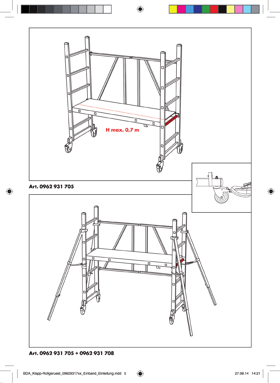
Aufbau der Grundeinheit
(Art. 0962 931 705), bestehend aus:
• 1 Stück klappbarem Gerüstrahmen
• 1 Stück Gerüstplattform
A1: Die mittels zwei Einhängehaken am Klapp-
rahmen xierte Gerüstplattform wird abgenommen
und zur Seite gestellt.
A2: Der Alu-Klapprahmen wird nach Önen des
Klettbandverschlusses aufgeklappt.
A3: Durch Einhängen der Gerüstplattform wird die
Klapp-Rollgerüst-Einheit selbstsichernd xiert.
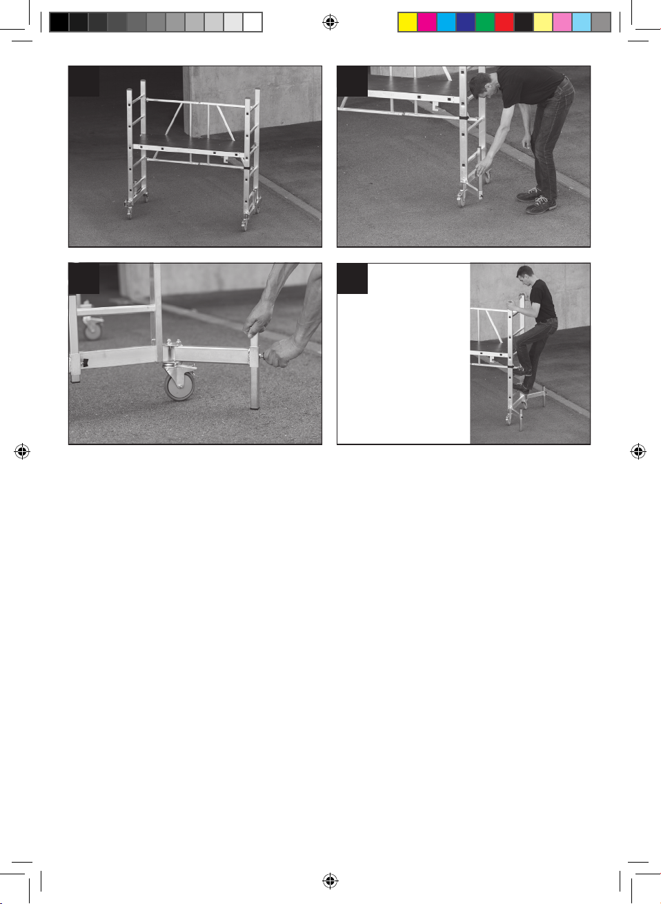
A4: Die Lenkrollen am Gerüst werden per Stopp-
hebel in Bremsstellung gebracht.
Anbringung der Teleskopstützen
(Art. 0962 931 708), bestehend aus:
• 4 Stück Teleskopstützen
A5: Die Schraubverbindung der jeweiligen Stütze
wird am Gerüstholm unterhalb der obersten Sprosse
angesetzt und festgeschraubt.
A6: Die an der Stütze vorhandene Kette wird
zwischen zweiter und dritter Sprosse um den Holm
geschlungen und mittels des vorhandenen Karabiner
eingehängt.
A7: Der Teleskopleiterfuß an der Stütze wird soweit
ausgeschoben, dass die eingehängte Kette durchge-
spannt ist. (Diese Vorgehensweise wiederholt sich bei
allen anzubringenden Teleskopstützen.)
A8: Durch die angebrachten Teleskopstützen ist ein
sicherer Aufstieg und eine absolute Kippsicherheit des
Klapp-Rollgerüstes gewährleistet.
Anbringung des Geländersatzes
(Art. 0962 931 703), bestehend aus:
• 4 Stück Geländerpfosten
• 2 Stück Längs-Geländerrohren
• 2 Stück Quer-Geländerrohren
A9: Die Geländer-Stehpfosten werden mittels der
angebrachten Klemmverbindungen mit den jeweiligen
Gerüstholmen verbunden.
A10: Die Längs- bzw. Querrohre des Geländers
werden jeweils in 1 m Höhe über der eingesetzten
Plattform in den dafür vorgesehenen Bohrlöchern
mittels der beigefügten Klemm-Flügelschrauben
befestigt.
Nach dem Aufbau ist die Vollständigkeit
sowie der feste Sitz aller Verbindungen zu
überprüfen.
A11: Der Abbau des Klapp-Rollgerüsts erfolgt in
umgekehrter Reihenfolge.
Verbinden von zwei Klapp-Rollgerüsten
mittels der Verbindungsplattform
(Art. 0962 931 701) zu einem Flächen-
gerüst:
B1: Zwei nach A1–A4 der Aufbau- und Verwen-
dungsanweisung aufgebaute Klapp-Rollgerüste
werden längsseits im Abstand von ca. 50 cm zusam-
mengestellt.
Durch Einhängen der Verbindungsplattform werden
die beiden Gerüste zu einer Flächengerüst-Einheit
verbunden.
B2: An allen vier Eckenpfosten der Flächengerüst-
Einheit werden die Ausleger-Schrägabstützungen wie
unter A5–A8 beschrieben angebracht.
B3: An der Flächengerüsteinheit werden umlaufend
die Geländerrohre wie unter A9–A11 beschrieben
angebracht und mittels der zwei Geländerverbin-
dungsrohre (Art. 0962 931 704) verbunden.
• Nach dem Aufbau ist die Vollständigkeit sowie der
feste Sitz aller Verbindungen zu überprüfen.
• Das Gerüst auf vertikale Ausrichtung prüfen.
• Der Abbau des Klapp-Rollgerüsts erfolgt in
umgekehrter Reihenfolge.
Aufbau Aufbauvariante C
• C1: Die Grundeinheit des Klapp-Rollgerüsts „Pro“
wird wie in A1–A4 beschrieben aufgebaut.
• C2: Integrierte Kippsicherung bis zum Anschlag
nach außen klappen.
• C3: Teleskopstützen ausfahren und festschrauben
• Diese Vorgehensweise an allen 4 Stützen wieder-
holen.
• C4: Durch die angebrachten Kippsicherungen ist
ein sicherer Aufstieg und eine optimale Kippsicher-
heit des Gerüsts gewährleistet.

3
Gewährleistung
Für dieses Würth-Produkt bieten wir eine Gewährleis-
tung gemäß den gesetzlichen/länderspezischen
Bestimmungen ab Kaufdatum (Nachweis durch
Rechnung oder Lieferschein). Entstandene Schäden
werden durch Ersatzlieferung oder Reparatur besei-
tigt.
Schäden, die auf natürliche Abnutzung, Überlastung
oder unsachgemäße Behandlung zurückzuführen
sind, werden von der Gewährleistung ausgeschlos-
sen.
Verwendung
• Der Auf- und Abbau und die Verwendung des
Klapp-Rollgerüsts außerhalb geschlossener Räume
ist nur bis Windstärken unter 6 Beaufort zulässig.
• Horizontale und vertikale Lasteinwirkungen, welche
ein Umkippen des Klapp-Rollgerüsts bewirken
können, sind zu vermeiden.
• Das Klapp-Rollgerüst darf nicht mit einem Kran o.ä.
angehoben und versetzt werden.
• Das Klapp-Rollgerüst darf nicht gefahren werden,
wenn sich Personen oder lose Gegenstände auf
der Belagäche benden.
• Zum Fahren des Klapp-Rollgerüsts müssen Bremsen
gelöst und die Teleskopfüße der Schrägabstützun-
gen eingeschoben werden.
• Nach dem Fahren sind die Schrägabstützungen
und die Bremsrollen wieder in ihre vorherige
Position zu bringen und deren Funktion zu über-
prüfen.
Prüfung, Pege, Instandhaltung
• Gerüstbauteile müssen sorgfältig behandelt und
transportiert werden, um Beschädigungen zu
vermeiden.
• Alle Bauteile sind auf Beschädigungen zu kontrol-
lieren.
• Alle beweglichen Teile sind auf einwandfreie
Funktion und Verschmutzung zu überprüfen.
• Beschädigte Komponenten sind zu ersetzen, zur
Reparatur an den Hersteller zu schicken, oder zu
vernichten.
Führen Sie einmal im Jahr eine Sicherheits-
inspektion durch:
• Einzelteile: vollständig vorhanden
• Aluminiumprole: nicht verbogen, Verbindungen
nicht locker
• Gerüstplattform: unbeschädigt
• Ketten und Karabinerhaken: unbeschädigt
• Bremsen: funktionsfähig

4
Technical Data
Foldable Rolling Scaold
Article overview:
Complete sets:
Complete Foldable Rolling Scaold Set
Variant A: Art. 0962 931 710
Complete Areal Scaold Set
Variant B: Art. 0962 931 720
Foldable Rolling Scaold “Pro”
Variant C: Art. 0962 931 706
Individual accessories:
Basic Foldable Rolling Scaold: Art. 0962 931 705
Telescopic strut set: Art. 0962 931 708
Railing set: Art. 0962 931 703
Railing connecting tubes: Art. 0962 931 704
Connecting platform: Art. 0962 931 701
Admissible load:
Variant A and C: 150 kg, 1 person
Variant B: 200 kg, 2 persons
Max. height of scaold platform:
Basic scaold without struts: 0.7 m (2nd rung)
Basic scaold with strut set: 1.0 m (3rd rung)
Foldable Rolling Scaold “Pro” 1.0 m (3rd rung)
With railing and strut set: 1.55 m (top rung)
Intended Use
The Foldable Rolling Scaold is a working scaold
which may only be used after proper assembly on
level surfaces in observance of the following safety
regulations. The user is liable for all damage resulting
from improper use.
Not a consumer product. For commercial and industri-
al use only!
For Your Safety
Before assembly and use of the
Foldable Rolling Scaold, read the
Instructions for Assembly and Use
carefully.
Please observe the indicated maximum
heights of the scaold platform in the
respective assembly variants. Above
the indicated heights, the scaold must be additional-
ly secured to prevent tipping using the Telescopic
Strut Set, Art. 0962 931 708.
Above a working height of the scaold platform of
1 m, the Railing Set (Art. 0962 931 703) must be
used.
• The platform area must not be enlarged by the use
of other devices.
• The Foldable Rolling Scaold must not be used
with parts from other manufacturers.
• Only the parts described in the Instructions for
Assembly and Use may be installed.
Caution: Damaged or faulty parts must not be
used.
• Only persons who have been instructed using the
Instructions for Assembly and Use may assemble,
use and disassemble the Foldable Rolling Scaold.
The Foldable Rolling Scaold can be assembled
and disassembled by one person.
Check the following points before assembly:
• The ground at the place of work must be level and
have a sucient load-bearing strength.
• Check the assembly location.
• There must be no obstacles around the assembly
location of the Foldable Rolling Scaold.
• Damaged or faulty parts or parts not belonging to
the system must be removed.
• The admissible wind conditions.
• The Instructions for Assembly and Use must be
available at the working location.
GB

5
Assembly
Assembly of the Base Unit
(Art. 0962 931 705), consisting of:
• 1 o folding scaold frame
• 1 o scaold platform
A1: Remove the scaold platform fastened to the
folding frame by two mounting hooks and place to
one side.
A2: Open the Velcro strap and unfold the folding
aluminium frame.
A3: Hooking in the scaold platform xes and locks
the Foldable Rolling Scaold.
A4: Move the castors on the frame to the “Brake”
position using the STOP levers.
Attaching the Telescopic Struts
(Art. 0962 931 708), consisting of:
• 4 o telescopic struts
A5: Insert the screw of the respective strut into the
holes in the frame posts below the top rung and
screw tight.
A6: Wrap the chain attached to the strut around the
frame post between second and third rung and
secure with the karabiner.
A7: Extend the foot of the telescopic ladder on the
strut until the attached chain is taut. (Repeat this
procedure at all the telescopic struts to be installed.)
A8: The attached telescopic strut ensures a safe
ascent and absolute safety against tipping of the
Foldable Rolling Scaold.
Attaching the Railing Set
(Art. 0962 931 703), consisting of:
• 4 o railing posts
• 2 o longitudinal railing tubes
• 2 o lateral railing tubes
A9: Connect the railing posts to the respective frame
posts using the attached clamps.
A10: Secure the longitudinal and lateral tubes of the
railing at a height of 1 m above the assembled
platform using the clamping wing bolts supplied
inserted into the bore holes provided.
After assembly, check the completeness
and tightness of all connections.
A11: The Foldable Rolling Scaold is disassembled
in the reverse order.
Connection of two Foldable Rolling Scaf-
folds with Connecting Platform
(Art. 0962 931 701) to form an areal scaf-
fold:
B1: Position two Foldable Rolling Scaolds assem-
bled as described in A1–A4 of the Instructions for
Assembly and Use with their longitudinal sides ap-
prox. 50 cm apart.
Hook in the Connecting Platform to convert the two
scaolds into an areal scaold unit.
B2: Attach the angled boom supports to all four
corner posts of the areal scaold unit as described
under A5–A8.
B3: Install the railing tubes all around the areal
scaold unit as described under A9–A11 and
connect using the two railing connecting tubes (Art.
0962 931 704).
• After assembly, check the completeness and
tightness of all connections.
• Check the scaold for vertical alignment.
• The Foldable Rolling Scaold is disassembled in
the reverse order.
Assembly – Variant C
• C1: Assemble the base unit of the Foldable Rolling
Scaold “Pro” as described in A1–A4.
• C2: Fold out the integrated anti-tipping system until
the stop.
• C3: Extend the telescopic struts and bolt in place.
• Repeat this procedure at all 4 posts.
• C4: The attached anti-tipping system ensures a safe
ascent and absolute safety against tipping of the
scaold.

6
Warranty
This Würth product is covered by warranty according
to the applicable statutory national regulations. The
warranty period begins on the date of purchase
(please retain invoice or delivery note as proof of
purchase). Any damage will be remedied by a
substitute delivery or by repair.
Damage caused by normal wear and tear, overload
or improper operation is not covered by warranty.
Use
• The assembly, use and disassembly of the Foldable
Rolling Scaold outdoors is permitted only at wind
forces below 6 Beaufort.
• Horizontal and vertical loads which could cause
the Foldable Rolling Scaold to tip over must be
avoided.
• The Foldable Rolling Scaold must not be lifted or
moved using a crane or other lifting equipment.
• The Foldable Rolling Scaold must not be moved
when persons or loose objects are on the platform.
• Before moving the Foldable Rolling Scaold,
release the brakes and push in the telescopic legs
of the angled struts.
• After moving, return the angled struts and the
castor brakes to their previous position and check
their function.
Inspection, Care, Maintenance
• Handle and transport all scaold parts carefully in
order to avoid damage.
• Inspect all parts for damage.
• Inspect all moving parts for proper function and
soiling.
• Damaged parts must be replaced, returned to the
manufacturer for repair or scrapped.
Carry out a safety inspection once a year:
• Individual parts: All parts present
• Aluminium proles: Not bent, connections not loose
• Scaold platform: Undamaged
• Chains and carabiners: Undamaged
• Brakes: Fully functional

7
Dati tecnici
Ponteggio pieghevole su ruote
Panoramica dell'articolo:
Set completi:
Ponteggio pieghevole su ruote, set completo
Variante strutturale A: Art. 0962 931 710
Set completo per ponteggio orizzontale
Variante strutturale B: Art. 0962 931 720
Ponteggio pieghevole su ruote "Pro"
Variante strutturale C: Art. 0962 931 706
Accessori singoli:
Ponteggio pieghevole di base su ruote:
Art. 0962 931 705
Serie di sostegni telescopici: Art. 0962 931 708
Serie di ringhiere: Art. 0962 931 703
Tubi di collegamento delle ringhiere:
Art. 0962 931 704
Piattaforma di collegamento: Art. 0962 931 701
Carico consentito:
Varianti strutturali A e C: 150 kg, 1 persona
Variante strutturale B: 200 kg, 2 persone
Altezza max. della piattaforma del ponteg-
gio:
Ponteggio di base senza sostegni:
0,7 m (2ª traversa)
Ponteggio di base con serie di sostegni:
1,0 m (3ª traversa)
Ponteggio pieghevole su ruote "Pro":
1,0 m (3ª traversa)
Con serie di ringhiere e sostegni:
1,55 m (traversa superiore)
Uso conforme alle norme
Il ponteggio pieghevole su ruote è un ponteggio di
lavoro che può essere utilizzato solo su superci in
piano tenendo conto delle seguenti norme di sicurez-
za e dopo essere stato montato secondo le istruzioni.
La responsabilità per i danni dovuti ad un utilizzo non
conforme alle norme è esclusivamente dell'utente.
Il prodotto non è rivolto ad un'utenza non specializ-
zata. Solo per uso professionale.
Informazioni per la sicurezza
Prima del montaggio e dell'utiliz-
zo del ponteggio pieghevole su
ruote è necessario aver letto
accuratamente le istruzioni d'uso
e montaggio.
Rispettare le altezze massime indicate per
la piattaforma del punteggio nelle rispetti-
ve varianti strutturali. Al di sopra
delle altezze indicate è necessario ssare i punteggi
con l'aggiunta della serie di sostegni telescopici
Art. 0962 931 708 per evitare il ribaltamento.
Se si utilizza la piattaforma del ponteggio ad altezze
superiori a 1 m, è necessario utilizzare la serie di
ringhiere (Art. 0962 931 703).
• La supercie di appoggio non deve essere ingran-
dita con ulteriori elementi.
• Il ponteggio pieghevole su ruote non deve essere
utilizzato con componenti di altri costruttori.
• Montare esclusivamente i componenti indicati nelle
istruzioni d'uso e montaggio.
Attenzione: I componenti danneggiati o difettosi
non devono essere utilizzati.
• Il montaggio, lo smontaggio e l'uso del ponteggio
pieghevole su ruote sono consentiti solo a persone
qualicate sulla base delle istruzioni d'uso e mon-
taggio. Il montaggio e lo smontaggio possono
essere svolti da un'unica persona.
Prima del montaggio è necessario control-
lare i seguenti punti:
• Il sottofondo deve essere in piano e di portata
suciente.
• Il punto di appoggio deve essere controllato.
• Intorno al punto di appoggio del punteggio pie-
ghevole su ruote non devono trovarsi ostacoli.
• I componenti danneggiati, difettosi o non facenti
parte del sistema devono essere eliminati.
• Rispettare le condizioni di vento consentite.
• Le istruzioni d'uso e montaggio devono trovarsi sul
luogo di utilizzo.
IT

8
Montaggio
Montaggio dell'unità di base
(Art. 0962 931 705), composta da:
• 1 x telaio del ponteggio pieghevole
• 1 x piattaforma del ponteggio
A1: rimuovere e mettere da parte la piattaforma del
ponteggio, ssata al telaio pieghevole per mezzo di
due ganci.
A2: aprire il telaio pieghevole in alluminio dopo aver
aperto la chiusura a velcro.
A3: ssare con lo scatto automatico l'unità del
ponteggio pieghevole su ruote agganciando la
piattaforma del ponteggio.
A4: le ruote girevoli del ponteggio possono essere
bloccate in posizione frenata con la leva di arresto.
Montaggio dei sostegni telescopici
(Art. 0962 931 708), composti da:
• 4 x sostegni telescopici
A5: posizionare e serrare il collegamento a vite di
ciascun sostegno al longherone del ponteggio sotto
la traversa più alta.
A6: far passare la catena del sostegno intorno al
longherone fra la seconda e la terza traversa e
agganciarla per mezzo del moschettone.
A7: spingere il piede della scaletta telescopica del
sostegno no a tendere completamente la catena
agganciata (questa procedura deve essere ripetuta
per tutti i sostegni telescopici da montare).
A8: i sostegni telescopici montati permettono di salire
in sicurezza ed evitare assolutamente il ribaltamento
del ponteggio pieghevole su ruote.
Montaggio della serie di ringhiere
(Art. 0962 931 703), composta da:
• 4 x pali delle ringhiere
• 2 x tubi longitudinali delle ringhiere
• 2 x tubi trasversali delle ringhiere
A9: collegare i pali delle ringhiere ai rispettivi lon-
gheroni del ponteggio con i collegamenti a morsetto
già posizionati.
A10: ssare i tubi longitudinali e trasversali delle
ringhiere con le viti ad alette e morsetto in dotazione,
a 1 m di altezza al di sopra della piattaforma monta-
ta inlandoli negli appositi fori.
Dopo il montaggio, vericare la completez-
za e il corretto ssaggio di tutti i collega-
menti.
A11: Lo smontaggio del ponteggio pieghevole su
ruote avviene nell'ordine inverso.
Collegamento di due ponteggi pieghevoli
su ruote per mezzo della piattaforma di
collegamento (Art. 0962 931 701) per
ottenere un ponteggio orizzontale:
B1: aancare i lati lunghi di due ponteggi pieghevoli
su ruote montati secondo le istruzioni d'uso e montag-
gio A1–A4 a una distanza di circa 50 cm.
Agganciare la piattaforma di collegamento per unire
i due ponteggi e ottenere un singolo ponteggio
orizzontale.
B2: su ciascuno dei quattro pali d'angolo del ponteg-
gio orizzontale posizionare i sostegni a braccio
diagonali come descritto in A5–A8.
B3: posizionare i tubi delle ringhiere lungo il perime-
tro del ponteggio orizzontale come descritto in
A9–A11 e collegarli per mezzo di due tubi di
collegamento delle ringhiere (Art. 0962 931 704).
• Dopo il montaggio, vericare la completezza e il
corretto ssaggio di tutti i collegamenti.
• Controllare l'allineamento verticale del ponteggio.
• Lo smontaggio del ponteggio pieghevole su ruote
avviene nell'ordine inverso.
Montaggio della variante strutturale C
• C1: montare l'unità di base del ponteggio pieghe-
vole su ruote "Pro" come descritto in A1–A4.
• C2: aprire verso l'esterno la protezione antiribalta-
mento integrata no a battuta.
• C3: estrarre e serrare i sostegni telescopici.
• Ripetere questa procedura per ciascuno dei 4
sostegni.
• C4: le protezioni antiribaltamento montate permet-
tono di salire in sicurezza e una protezione ottima-
le contro il ribaltamento del ponteggio.

9
Garanzia
Per il presente prodotto Würth il costruttore fornisce
una garanzia secondo le disposizioni di legge o
speciche del paese dal momento dell'acquisto (da
dimostrare con fattura o bolla d'accompagnamento).
In caso di danni, il prodotto verrà sostituito o riparato.
Si esclude la garanzia per i danni riconducibili ad
usura naturale, sovraccarico o uso improprio.
Uso
• Il montaggio, lo smontaggio e l'utilizzo del ponteg-
gio pieghevole su ruote all'aperto sono consentiti
solo con un'intensità del vento inferiore a 6 Beau-
fort.
• Evitare eetti di carico orizzontale e verticale che
possano comportare un ribaltamento del ponteg-
gio pieghevole su ruote.
• Il ponteggio pieghevole su ruote non deve essere
sollevato e spostato con gru o simili.
• Il ponteggio pieghevole su ruote non deve essere
spostato se sulla supercie di rivestimento si trova-
no persone od oggetti non ssati.
• Per spostare il ponteggio pieghevole su ruote è
necessario rilasciare i freni e chiudere i piedi
telescopici dei sostegni diagonali.
• Dopo lo spostamento è necessario riportare i
sostegni diagonali e le ruote frenanti in posizione
iniziale e vericarne il funzionamento.
Controllo, cura, manutenzione
• I componenti del ponteggio devono essere maneg-
giati e trasportati con cura per evitare di danneg-
giarli.
• Cercare eventuali danni su tutti i componenti.
• Controllare il perfetto funzionamento e l'eventuale
presenza di impurità su tutti i componenti mobili.
• I componenti danneggiati devono essere sostituiti,
rispediti al costruttore per la riparazione o distrutti.
Eseguire un'ispezione di sicurezza una
volta all'anno:
• I particolari devono essere tutti presenti
• I proli in alluminio non devono essere piegati e i
collegamenti non devono essere allentati
• La piattaforma del ponteggio non deve essere
danneggiata
• Le catene e i moschettoni non devono essere
danneggiati
• I freni devono essere funzionanti

10
Caractéristiques techniques
Échafaudage roulant et pliant
Aperçu de l'article :
Kits complets :
Échafaudage roulant et pliant, kit complet
Variante de montage A : réf. 0962 931 710
Kit complet d'échafaudage de surfaces
Variante de montage B : réf. 0962 931 720
Échafaudage roulant et pliant « Pro »
Variante de montage C : réf. 0962 931 706
Accessoires :
Échafaudage de base roulant et pliant :
réf. 0962 931 705
Jeu de montants télescopiques : réf. 0962 931 708
Jeu de balustrade : réf. 0962 931 703
Barres de liaison de balustrade :
réf. 0962 931 704
Plateforme de liaison : réf. 0962 931 701
Charge de travail admissible :
Variante de montage A et C : 150 kg 1 personne
Variante de montage B : 200 kg 2 personnes
Hauteur maximale de la plateforme :
Échafaudage de base sans élément stabilisateur :
0,7 m (2ème échelon)
Échafaudage de base avec jeu de montants :
1,0 m (3ème échelon)
Échafaudage roulant et pliant « Pro » :
1,0 m (3ème échelon)
Avec stabilisateurs et balustrade :
1,55 m (échelon supérieur)
Utilisation conforme
L'échafaudage roulant et pliant est un échafaudage
de service qui une fois monté suivant les prescriptions,
ne doit être utilisé que sur des surfaces planes, dans
le respect des prescriptions de sécurité suivantes. Seul
l'utilisateur est responsable des dommages résultant
d'une utilisation non conforme.
Ce produit n'est pas un produit de consommation.
Produit destiné à un usage professionnel uniquement !
Pour votre sécurité
Lire attentivement les instructions
de montage et d'utilisation avant
de procéder au montage et de
commencer à utiliser l'échafau-
dage roulant et pliant.
Quelle que soit la variante de montage
choisie, veillez à respecter la hauteur
maximale indiquée pour la plateforme. Au
delà des hauteurs maximales indiquées, il convient de
sécuriser l'échafaudage et de le potéger contre le
risque de basculement à l'aide du jeu de montants
télescopiques réf. 0962 931 708.
En cas d'utilisation de la plateforme à une hauteur
supérieure à 1 m, il convient impérativement d'utiliser
le jeu de balustrade (réf. 0962 931 703).
• Ne pas tenter d'agrandir la taille du plateau à
l'aide d'outils auxiliaires.
• Ne pas combiner l'échafaudage roulant et pliant
avec des pièces originaires d'autres fabricants.
• Monter exclusivement les pièces mentionnées dans
les instructions de montage et d'utilisation.
Attention : ne pas utiliser les pièces endomma-
gées ou défectueuses.
• Seules les personnes ayant été initiées à partir des
instructions de montage et d'utilisation sont autori-
sées à monter et utiliser l'échafaudage roulant et
pliant. Le montage et le démontage peuvent être
eectués par une seule personne.
Vérier les points suivants avant de procé-
der au montage :
• Le sol doit être plan et susamment capable de
supporter la charge.
• L'emplacement doit faire l'objet d'une vérication.
• Aucun obstacle ne doit se trouver sur le lieu d'em-
placement de l'échafaudage roulant et pliant.
• Les pièces endommagées, défectueuses ou étran-
gères au système doivent être éliminées.
• Veiller à ce que les conditions de vent soient
conformes.
• Les instructions de montage et d'utilisation doivent
se trouver sur le lieu d'utilisation.
FR

11
Montage
Montage de l'unité de base
(réf. 0962 931 705), comprenant :
• 1 cadre d'échafaudage pliant
• 1 plateforme
A1 : Retirer la plateforme xée au cadre pliant par
deux crochets et la mettre de côté.
A2 : Déplier le cadre pliant en aluminium après avoir
ouvert la fermeture Velcro.
A3 : La plateforme une fois accrochée, l'échafau-
dage roulant et pliant est stable.
A4 : Les roulettes de direction de l'échafaudage
peuvent être bloquées en position d'arrêt à l'aide de
leviers.
Montage des montants télescopiques
(réf. 0962 931 708), comprenant :
• 4 montants télescopiques
A5 : Placer le raccord à vis du montant correspon-
dant sur le prol de l'échafaudage, en dessous de
l'échelon le plus élevé, puis visser fermement.
A6 : Enrouler la chaîne du montant autour du prol,
entre le second et le troisième échelon, puis l'accro-
cher à l'aide du mousqueton.
A7 : Extraire le pied de l'échelle télescopique du
montant jusqu'à ce que la chaîne soit tendue. (Répé-
ter cette opération pour tous les montants télesco-
piques à monter.)
A8 : Les montants télescopiques montés permettent
au personnel de monter sur l'échafaudage en toute
sécurité et protègent ce dernier de manière optimale
contre le basculement.
Montage du jeu de balustrade
(réf. 0962 931 703), comprenant :
• 4 montants de balustrade
• 2 barres longitudinales de balustrade
• 2 barres transversales de balustrade
A9 : Les montants verticaux de la balustrade sont
reliés aux prols respectifs de l'échafaudage au
moyen de dispositifs de serrage pré-montés.
A10 : Les barres longitudinales et transversales de la
balustrade sont xées dans les trous prévus à cet eet
au moyen des vis papillon jointes, chacune à 1 m de
hauteur au-dessus de la plateforme préalablement
mise en place.
Le montage une fois terminé, vérier qu'au-
cune xation n'a été oubliée et que toutes
sont correctement serrées.
A11 : Le démontage de l'échafaudage roulant et
pliant s'eectue dans l'ordre inverse.
Raccordement de deux échafaudages
roulants et pliants au moyen d'une plate-
forme de liaison
(réf. 0962 931 701) pour obtenir un écha-
faudage de surfaces :
B1 : Après avoir monté deux échafaudages roulants
et pliants conformément aux instructions de montage
A1–A4 , les placer côte à côte, à une distance
d'env. 50 cm l'un de l'autre.
Accrocher la plateforme de liaison pour relier les
deux échafaudages et former ainsi une unité d'écha-
faudage de surfaces.
B2 : Monter les bras obliques de stabilisation sur les
quatre montants d'angle tel que décrit sous A5–A8 .
B3 : Monter ensuite les barres de balustrade tout
autour de l'unité d'échafaudage de surfaces tel que
décrit sous A9–A11 puis les relier à l'aide des deux
barres de liaison de balustrade (réf. 0962 931 704).
• Le montage une fois terminé, vérier qu'aucune
xation n'a été oubliée et que toutes sont correcte-
ment serrées.
• Contrôler que l'échafaudage soit bien aligné
verticalement.
• Le démontage de l'échafaudage roulant et pliant
s'eectue dans l'ordre inverse.
Variante de montage C
• C1 : L'unité de base de l'échafaudage roulant et
pliant « Pro » se monte tel que décrit dans les
étapes A1–A4.
• C2 : Rabattre la protection anti-basculement vers
l'extérieur, jusqu'à la butée.
• C3 : Déployer les montants télescopiques et les
visser fermement.
• Répéter cette action pour les 4 montants.
• C4 : Les protections anti-basculement permettent au
personnel de monter sur l'échafaudage en toute
sécurité et protègent ce dernier de manière opti-
male contre le basculement.

12
Garantie
Ce produit Würth bénécie d'une garantie conforme
à la réglementation légale / spécique au pays et
valide à compter de la date d'achat (preuve par
facture ou bon de livraison). Les dommages éventuels
sont éliminés soit par livraison d'un produit de rempla-
cement, soit par réparation.
Les dommages dus à une usure naturelle, à une
surcharge ou à une manipulation non conforme sont
exclus de la garantie.
Avertissement
Conformément aux exigences du Code du travail
(Art. R 4323-58, 59, 60 et 61), pour tout travail en
hauteur (quelle que soit la hauteur), il appartient à
l’employeur de mettre impérativement en œuvre les
dispositifs susants de manière à préserver la santé
et la sécurité des travailleurs.
Ces dispositifs peuvent être de formes diverses, tel
que :
• Dispositif collectif, type garde-corps
(Art. R 4323-59) ou recueil souple
(Art. R 4323-60), ou
• Dispositif individuel, type harnais de sécurité
(Art. R 4323-61).
Version 1 – Juin 2014
Utilisation
• Le montage / démontage et l'utilisation de l'écha-
faudage roulant et pliant en extérieur ne sont
autorisés que jusqu'à un vent d'une force de 6
Beaufort.
• Éviter toute charge horizontale et verticale pouvant
provoquer un basculement de l'échafaudage
roulant et pliant.
• L'échafaudage roulant et pliant ne doit ni être
soulevé, ni être déplacé par une grue ou un engin
similaire.
• Ne pas déplacer l'échafaudage tant que des
personnes ou des objets se trouvent sur le plateau.
• Pour faire rouler l'échafaudage, desserrer les freins
puis rentrer les pieds télescopiques des stabilisa-
teurs obliques.
• Une fois l'échafaudage déplacé, remettre les
stabilisateurs et les freins dans leur position initiale
et vérier qu'ils fonctionnent parfaitement.
Contrôles, entretien, maintenance
• Manipuler et transporter les diérents composants
de l'échafaudage avec soin an d'éviter tout
endommagement.
• Contrôler le bon état de l'ensemble des compo-
sants.
• Soumettre l'ensemble des pièces mobiles à un
contrôle de fonctionnement et de propreté.
• Remplacer les composants endommagés, les
retourner au fabricant pour réparation ou les
détruire.
Eectuez une inspection de sécurité une fois
par an :
• Pièces détachées : complètes
• Prols en aluminium : non déformés, connexions
toutes serrées
• Plateforme : non endommagée
• Chaînes et mousquetons : en bon état
• Freins : fonctionnels
This manual suits for next models
3
Table of contents
Languages:
Popular Construction Equipment manuals by other brands

MetalTech
MetalTech JOBSITE I-IDS1830 OPERATIONAL SAFETY AND ASSEMBLY INSTRUCTIONS

Graco
Graco LineLazer IV 250MMA Operation, parts

Clarke
Clarke CFC2000 Assembly instructions

Yongmao
Yongmao STT113 Operation & service manual

Miracle Paint
Miracle Paint Blue Boy MBB-5-C owner's manual

Manitowoc
Manitowoc National Crane 1300A Operator's manual

stellar labs
stellar labs 14530 owner's manual

Ingersoll-Rand
Ingersoll-Rand Free Standing WorkstationCranes Product information

EINHELL
EINHELL RT-MX 1600 E operating instructions

CASE CONSTRUCTION
CASE CONSTRUCTION 1150M Operator's manual

DC
DC HP Installation

Weber mt
Weber mt VPR 450 Operating and maintenance manual