WÄRTSILÄ WARTSILA32 User manual

Lib Version: a1747 / 12.2009 / Bock´s Office / Arkmedia / Multiprint
WÄRTSILÄ 32
PRODUCT GUIDE
WÄRTSILÄ 32 – PRODUCT GUIDE
WÄRTSILÄ® is a registered trademark. Copyright © 2009 Wärtsilä Corporation.
Wärtsilä is a global leader in complete lifecycle power solutions for the
marine and energy markets. By emphasising technological innovation
and total efficiency, Wärtsilä maximises the environmental and economic
performance of the vessels and power plants of its customers. Wärtsilä is
listed on the NASDAQ OMX Helsinki, Finland.

© Copyright by WÄRTSILÄ FINLAND OY
All rights reserved. No part of this booklet may be reproduced or copied in any form or by any means (electronic,
mechanical, graphic, photocopying, recording, taping or other information retrieval systems) without the prior written
permission of the copyright owner.
THIS PUBLICATION IS DESIGNED TO PROVIDE AN ACCURATE AND AUTHORITATIVE INFORMATION WITH
REGARD TO THE SUBJECT-MATTER COVERED AS WAS AVAILABLE AT THE TIME OF PRINTING. HOWEVER,THE
PUBLICATION DEALS WITH COMPLICATED TECHNICAL MATTERS SUITED ONLY FOR SPECIALISTS IN THE
AREA, AND THE DESIGN OF THE SUBJECT-PRODUCTS IS SUBJECT TO REGULAR IMPROVEMENTS,
MODIFICATIONS AND CHANGES. CONSEQUENTLY, THE PUBLISHER AND COPYRIGHT OWNER OF THIS
PUBLICATION CAN NOT ACCEPT ANY RESPONSIBILITY OR LIABILITY FOR ANY EVENTUAL ERRORS OR
OMISSIONS IN THIS BOOKLET OR FOR DISCREPANCIES ARISING FROM THE FEATURES OF ANY ACTUAL ITEM
IN THE RESPECTIVE PRODUCT BEING DIFFERENT FROM THOSE SHOWN IN THIS PUBLICATION. THE PUBLISHER
AND COPYRIGHT OWNER SHALL UNDER NO CIRCUMSTANCES BE HELD LIABLE FOR ANY FINANCIAL
CONSEQUENTIAL DAMAGES OR OTHER LOSS, OR ANY OTHER DAMAGE OR INJURY, SUFFERED BY ANY
PARTY MAKING USE OF THIS PUBLICATION OR THE INFORMATION CONTAINED HEREIN.

Introduction
This Product Guide provides data and system proposals for the early design phase of marine
engine installations. For contracted projects specific instructions for planning the installation
are always delivered. Any data and information herein is subject to revision without notice.
This 2/2016 issue replaces all previous issues of the Wärtsilä 32 Project Guides.
UpdatesPublishedIssue
Technical data updated07.09.20162/2016
Technical data updated06.09.20161/2016
Information for operating in arctic conditions updated.11.09.20152/2015
Material for air assist and operation in Arctic conditions added. Other updates
throughout the product guide.
25.02.20151/2015
Chapter Technical Data updated. Other minor updates.13.06.20141/2014
Wärtsilä, Marine Solutions
Vaasa, September 2016
Wärtsilä 32 Product Guide - a21 - 7 September 2016 iii
IntroductionWärtsilä 32 Product Guide

Table of contents
1-11. Main Data and Outputs .......................................................................................................................
1-11.1 Maximum continuous output .......................................................................................................
1-31.2 Reference conditions ...................................................................................................................
1-31.3 Operation in inclined position .....................................................................................................
1-31.4 Arctic package description ..........................................................................................................
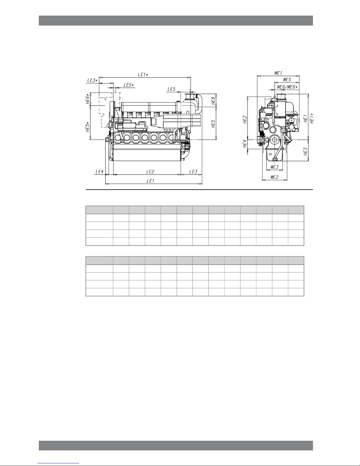
1-41.5 Dimensions and weights .............................................................................................................
2-12. Operating Ranges ................................................................................................................................
2-12.1 Engine operating modes ..............................................................................................................
2-12.2 Engine operating range ...............................................................................................................
2-42.3 Loading capacity .........................................................................................................................
2-62.4 Operation at low load and idling ..................................................................................................
2-62.5 Low air temperature ....................................................................................................................
3-13. Technical Data ......................................................................................................................................
3-13.1 Wärtsilä 6L32, 720 rpm ...............................................................................................................
3-43.2 Wärtsilä 6L32, 750 rpm ...............................................................................................................
3-83.3 Wärtsilä 8L32, 720 rpm ...............................................................................................................
3-113.4 Wärtsilä 8L32, 750 rpm ...............................................................................................................
3-143.5 Wärtsilä 9L32, 720 rpm ...............................................................................................................
3-173.6 Wärtsilä 9L32, 750 rpm ...............................................................................................................
3-213.7 Wärtsilä 12V32, 720 rpm .............................................................................................................
3-243.8 Wärtsilä 12V32, 750 rpm .............................................................................................................
3-273.9 Wärtsilä 16V32, 720 rpm .............................................................................................................
3-303.10 Wärtsilä 16V32, 750 rpm .............................................................................................................
4-14. Description of the Engine ....................................................................................................................
4-14.1 Definitions ....................................................................................................................................
4-14.2 Main components and systems ..................................................................................................
4-64.3 Cross section of the engine .........................................................................................................
4-84.4 Overhaul intervals and expected life times ..................................................................................
4-84.5 Engine storage .............................................................................................................................
5-15. Piping Design, Treatment and Installation .........................................................................................
5-15.1 Pipe dimensions ..........................................................................................................................
5-25.2 Trace heating ...............................................................................................................................
5-25.3 Pressure class ..............................................................................................................................
5-35.4 Pipe class ....................................................................................................................................
5-45.5 Insulation .....................................................................................................................................
5-45.6 Local gauges ...............................................................................................................................
5-45.7 Cleaning procedures ...................................................................................................................
5-55.8 Flexible pipe connections ............................................................................................................
5-65.9 Clamping of pipes ........................................................................................................................
6-16. Fuel Oil System ....................................................................................................................................
6-16.1 Acceptable fuel characteristics ...................................................................................................
6-86.2 Internal fuel oil system .................................................................................................................
6-106.3 External fuel oil system ................................................................................................................
7-17. Lubricating Oil System ........................................................................................................................
7-17.1 Lubricating oil requirements ........................................................................................................
7-37.2 Internal lubricating oil system ......................................................................................................
7-117.3 External lubricating oil system .....................................................................................................
iv Wärtsilä 32 Product Guide - a21 - 7 September 2016
Wärtsilä 32 Product GuideTable of contents

7-167.4 Crankcase ventilation system ......................................................................................................
7-177.5 Flushing instructions ....................................................................................................................
8-18. Compressed Air System ......................................................................................................................
8-18.1 Instrument air quality ...................................................................................................................
8-18.2 Internal compressed air system ..................................................................................................
8-68.3 External compressed air system .................................................................................................
9-19. Cooling Water System .........................................................................................................................
9-19.1 Water quality ...............................................................................................................................
9-29.2 Internal cooling water system ......................................................................................................
9-59.3 External cooling water system ....................................................................................................
10-110. Combustion Air System .......................................................................................................................
10-110.1 Engine room ventilation ...............................................................................................................
10-310.2 Combustion air system design ....................................................................................................
11-111. Exhaust Gas System ............................................................................................................................
11-111.1 Internal exhaust gas system ........................................................................................................
11-511.2 Exhaust gas outlet .......................................................................................................................
11-711.3 External exhaust gas system .......................................................................................................
12-112. Turbocharger Cleaning ........................................................................................................................
12-112.1 Turbine cleaning system ..............................................................................................................
12-212.2 Compressor cleaning system ......................................................................................................
13-113. Exhaust Emissions ...............................................................................................................................
13-113.1 Diesel engine exhaust components ............................................................................................
13-213.2 Marine exhaust emissions legislation ..........................................................................................
13-613.3 Methods to reduce exhaust emissions ........................................................................................
14-114. Automation System .............................................................................................................................
14-114.1 UNIC C2 .......................................................................................................................................
14-614.2 Functions ....................................................................................................................................
14-814.3 Alarm and monitoring signals ......................................................................................................
14-814.4 Electrical consumers ...................................................................................................................
15-115. Foundation ............................................................................................................................................
15-115.1 Steel structure design ..................................................................................................................
15-115.2 Mounting of main engines ...........................................................................................................
15-1415.3 Mounting of generating sets ........................................................................................................
15-1715.4 Flexible pipe connections ............................................................................................................
16-116. Vibration and Noise ..............................................................................................................................
16-116.1 External forces and couples ........................................................................................................
16-216.2 Torque variations .........................................................................................................................
16-316.3 Mass moments of inertia .............................................................................................................
16-316.4 Air borne noise .............................................................................................................................
16-416.5 Exhaust noise ..............................................................................................................................
17-117. Power Transmission ............................................................................................................................
17-117.1 Flexible coupling ..........................................................................................................................
17-217.2 Clutch ..........................................................................................................................................
17-217.3 Shaft locking device ....................................................................................................................
17-317.4 Power-take-off from the free end ................................................................................................
17-417.5 Input data for torsional vibration calculations .............................................................................
17-517.6 Turning gear .................................................................................................................................
Wärtsilä 32 Product Guide - a21 - 7 September 2016 v
Table of contentsWärtsilä 32 Product Guide

18-118. Engine Room Layout ...........................................................................................................................
18-118.1 Crankshaft distances ...................................................................................................................
18-1218.2 Space requirements for maintenance .........................................................................................
18-1218.3 Transportation and storage of spare parts and tools ..................................................................
18-1218.4 Required deck area for service work ...........................................................................................
19-119. Transport Dimensions and Weights ...................................................................................................
19-119.1 Lifting of main engines ................................................................................................................
19-319.2 Lifting of generating sets .............................................................................................................
19-419.3 Engine components .....................................................................................................................
20-120. Product Guide Attachments ...............................................................................................................
21-121. ANNEX ...................................................................................................................................................
21-121.1 Unit conversion tables .................................................................................................................
21-221.2 Collection of drawing symbols used in drawings ........................................................................
vi Wärtsilä 32 Product Guide - a21 - 7 September 2016
Wärtsilä 32 Product GuideTable of contents

1. Main Data and Outputs
The Wärtsilä 32 is a 4-stroke, non-reversible, turbocharged and intercooled diesel engine with
direct fuel injection.
320 mmCylinder bore ........................
400 mmStroke ...................................
32.2 l/cylinderPiston displacement .............
2 inlet valves
2 exhaust valves
Number of valves .................
6, 7, 8 and 9 in-line
12, 16 and 18 in V-form
Cylinder configuration .........
55°V-angle .................................
Clockwise, counterclockwise on requestDirection of rotation .............
720, 750 rpmSpeed ...................................
9.6, 10.0 m/sMean piston speed ...............
1.1 Maximum continuous output
Table 1-1 Rating table for Wärtsilä 32
Generating setsMain enginesCylinder
configuration 750 rpm720 rpm750 rpm
Generator
[kVA]
Engine [kW]Generator
[kVA]
Engine [kW][kW]
36003000346028803000
W 6L32
41803480403033603480
42003500403033603500W 7L32
48004000461038404000
W 8L32
55704640538044804640
54004500518043204500
W 9L32
62605220605050405220
72006000691057606000
W 12V32
83506960806067206960
96008000922076808000
W 16V32
1114092801075089609280
1080090001037086409000W 18V32
The mean effective pressure Pe can be calculated as follows:
Wärtsilä 32 Product Guide - a21 - 7 September 2016 1-1
1. Main Data and OutputsWärtsilä 32 Product Guide

where:
mean effective pressure [bar]Pe =
output per cylinder [kW]P =
engine speed [r/min]n =
cylinder diameter [mm]D =
length of piston stroke [mm]L =
operating cycle (4)c =
1-2 Wärtsilä 32 Product Guide - a21 - 7 September 2016
Wärtsilä 32 Product Guide1. Main Data and Outputs

1.2 Reference conditions
The output is available up to a charge air coolant temperature of max. 38°C and an air
temperature of max. 45°C. For higher temperatures, the output has to be reduced according
to the formula stated in ISO 3046-1:2002 (E).
The specific fuel oil consumption is stated in the chapter Technical data. The stated specific
fuel oil consumption applies to engines with engine driven pumps, operating in ambient
conditions according to ISO 15550:2002 (E). The ISO standard reference conditions are:
100 kPatotal barometric pressure
25°Cair temperature
30%relative humidity
25°Ccharge air coolant temperature
Correction factors for the fuel oil consumption in other ambient conditions are given in standard
ISO 3046-1:2002.
1.3 Operation in inclined position
Max. inclination angles at which the engine will operate satisfactorily.
Table 1-2 Inclination with Normal Oil Sump
15°
●Transverse inclination, permanent (list)
22.5°
●Transverse inclination, momentary (roll)
10°
●Longitudinal inclination, permanent (trim)
10°
●Longitudinal inclination, momentary (pitch)
1.4 Arctic package description
When a vessel is operating in cold ambient air conditions and the combustion air to the engine
is taken directly from the outside air, the combustion air temperature and thus also the density
is outside the normal range specified for the engine operation. Special arrangements are
needed to ensure correct engine operation both at high and at low engine loading conditions.
Read more about the special arrangements in chapters Combustion air system design in arctic
conditions,Cooling water system for arctic conditions and Lubricating oil system in arctic
conditions.
Wärtsilä 32 Product Guide - a21 - 7 September 2016 1-3
1. Main Data and OutputsWärtsilä 32 Product Guide

1.5 Dimensions and weights
1.5.1 Main engines
Fig 1-1 In-line engines with 500kW/cyl (DAAE030112A)
WE2WE3LE4LE2HE3HE4HE2WE1HE1HE1*LE1LE1*Engine
135088025036701155500234523052490256052604980W 6L32
135088025041601155500234523052490256057505470W 7L32
135088025046501155500234523052295236062455960W 8L32
135088025051401155500234523052295236067306450W 9L32
WeightLE5LE5*WE6WE6*HE6HE6*HE5HE5*LE3LE3*WE5Engine
33.95051303606607107101780185011507751345W 6L32
38.25051303606607107101780185011507751345W 7L32
43.55051303606604204201780185011507751345W 8L32
47.75051303606604204201780185011507751345W 9L32
* Turbocharger at flywheel end.
All dimensions in mm. Weight in metric tons with liquids (wet sump) but without flywheel.
1-4 Wärtsilä 32 Product Guide - a21 - 7 September 2016
Wärtsilä 32 Product Guide1. Main Data and Outputs

Fig 1-2 In-line engines with 580kW/cyl (DAAF061578A)
WE2WE3LE4LE2HE3HE4HE2WE1HE1LE1Engine
1350880250367011555002345238022955130W 6L32
1350880250465011555002345261023756379W 8L32
1350880250514011555002345261023756869W 9L32
WeightLE5WE6HE6HE5LE3WE5Engine
35.4515375460178012151425W 6L32
43.67051340545178012851650W 8L32
49.27051340545178012851650W 9L32
* Turbocharger at flywheel end.
All dimensions in mm. Weight in metric tons with liquids (wet sump) but without flywheel.
Wärtsilä 32 Product Guide - a21 - 7 September 2016 1-5
1. Main Data and OutputsWärtsilä 32 Product Guide

Fig 1-3 V-engines with 500kW/cyl (DAAE035123A)
WE2WE3LE4LE2HE3HE4HE2WE1*WE1HE1*HE1LE1LE1*Engine
15901220300415014756502120302030202715266566156935W 12V32
15901220300527014756502120302030202480243077358060W 16V32
15901220300583014756502120302030202480243082958620W 18V32
WeightLE5LE5*WE6WE6*HE6*HE6HE5*HE5WE4LE3LE3*WE5Engine
59.559059060060071071019651915850173517351510W 12V32
73.559059060060042042019651915850173517351510W 16V32
78.959059060060042042019651915850173517351510W 18V32
* Turbocharger at flywheel end.
All dimensions in mm. Weight in metric tons with liquids (wet sump) but without flywheel.
1-6 Wärtsilä 32 Product Guide - a21 - 7 September 2016
Wärtsilä 32 Product Guide1. Main Data and Outputs

Fig 1-4 V-engines with 580kW/cyl (DAAF062155)
WE2WE3LE4LE2HE3HE4HE2WE1HE1LE1Engine
15901225300415012106502120290024306865W 12V32
15901225300527012106502120332525957905W 16V32
WeightLE5WE6HE6HE5WE4LE3WE5Engine
56.9555540470190585019851450W 12V32
71.1560575550202085019251665W 16V32
* Turbocharger at flywheel end.
All dimensions in mm. Weight in metric tons with liquids (wet sump) but without flywheel.
Wärtsilä 32 Product Guide - a21 - 7 September 2016 1-7
1. Main Data and OutputsWärtsilä 32 Product Guide

1.5.2 Generating sets
Fig 1-5 In-line engines with 500kW/cyl (DAAE030093)
* Actual dimensions might vary based on power output and turbocharger maker.
Weight**HA1HA2HA3HA4WA3WA2WA1LA4**LA2**LA3LA1**Engine
5739402345145010461600191022903160684511508345W 6L32
6941402345165010462000231026903650751511509215W 7L32
7739252345163010462000231026903710792011509755W 8L32
84392523451630104622002510289038258850115010475W 9L32
** Dependent on generator and flexible coupling.
All dimensions in mm. Weight in metric tons with liquids.
1-8 Wärtsilä 32 Product Guide - a21 - 7 September 2016
Wärtsilä 32 Product Guide1. Main Data and Outputs

Fig 1-6 In-line engines with 580kW/cyl (DAAF061592)
Weight**HA1HA2HA3HA4WA3*WA2*WA1*LA4*LA2*LA3LA1*Engine
56.98537452345145010461800211024903265687512158345W 6L32
75.760401023451630104620002310269037108555128510410W 8L32
85.650401023451630104622002510289038258870128510505W 9L32
* Dependent on generator and flexible coupling.
All dimensions in mm. Weight in metric tons with liquids.
Wärtsilä 32 Product Guide - a21 - 7 September 2016 1-9
1. Main Data and OutputsWärtsilä 32 Product Guide

Fig 1-7 V-engines with 500kW/cyl (DAAE039700B)
* Actual dimensions might vary based on power output and turbocharger maker.
Weight**HA1HA2HA3HA4WA3WA2WA1LA4**LA2**LA3LA1**Engine
96436521201700137522002620306037757955173510075W 12V32
121428021201850137522002620306037659020173511175W 16V32
133428021201850137525002920336038759690173511825W 18V32
** Dependent on generator and flexible coupling.
All dimensions in mm. Weight in metric tons with liquids.
1-10 Wärtsilä 32 Product Guide - a21 - 7 September 2016
Wärtsilä 32 Product Guide1. Main Data and Outputs

Fig 1-8 V-engines with 580kW/cyl (DAAF061875)
Weight**HA1HA2HA3HA4WA3WA2WA1LA4**LA2**LA3LA1**Engine
100.1413021201700137522002620306041308325198510700W 12V32
127.3444521201850137525002920336042459130192511465W 16V32
** Dependent on generator and flexible coupling.
All dimensions in mm. Weight in metric tons with liquids.
Wärtsilä 32 Product Guide - a21 - 7 September 2016 1-11
1. Main Data and OutputsWärtsilä 32 Product Guide

This page intentionally left blank

2. Operating Ranges
2.1 Engine operating modes
If the engine is configured for SCR use then it can be operated in two modes; IMO Tier 2 mode
and SCR mode. The mode can be selected by an input signal to the engine automation system.
In SCR mode the exhaust gas temperatures after the turbocharger are actively monitored and
adjusted to stay within the operating temperature window of the SCR.
2.2 Engine operating range
Below nominal speed the load must be limited according to the diagrams in this chapter in
order to maintain engine operating parameters within acceptable limits. Operation in the
shaded area is permitted only temporarily during transients. Minimum speed is indicated in
the diagram, but project specific limitations may apply.
2.2.1 Controllable pitch propellers
An automatic load control system is required to protect the engine from overload. The load
control reduces the propeller pitch automatically, when a pre-programmed load versus speed
curve (“engine limit curve”) is exceeded, overriding the combinator curve if necessary. The
engine load is derived from fuel rack position and actual engine speed (not speed demand).
The propulsion control must also include automatic limitation of the load increase rate.
Maximum loading rates can be found later in this chapter.
The propeller efficiency is highest at design pitch. It is common practice to dimension the
propeller so that the specified ship speed is attained with design pitch, nominal engine speed
and 85% output in the specified loading condition. The power demand from a possible shaft
generator or PTO must be taken into account. The 15% margin is a provision for weather
conditions and fouling of hull and propeller. An additional engine margin can be applied for
most economical operation of the engine, or to have reserve power.
Wärtsilä 32 Product Guide - a21 - 7 September 2016 2-1
2. Operating RangesWärtsilä 32 Product Guide

Fig 2-1 Operating field for CP Propeller, 500 kW/cyl, 750 rpm
Fig 2-2 Operating field for CP Propeller, 580 kW/cyl, 750 rpm
2-2 Wärtsilä 32 Product Guide - a21 - 7 September 2016
Wärtsilä 32 Product Guide2. Operating Ranges
Table of contents
Other WÄRTSILÄ Engine manuals

WÄRTSILÄ
WÄRTSILÄ 34DF Series User manual

WÄRTSILÄ
WÄRTSILÄ W-X62 User manual

WÄRTSILÄ
WÄRTSILÄ WARTSILA 26 User manual

WÄRTSILÄ
WÄRTSILÄ 31SG User manual

WÄRTSILÄ
WÄRTSILÄ VASA 6L32 User manual

WÄRTSILÄ
WÄRTSILÄ WARTSILA 20 User manual

WÄRTSILÄ
WÄRTSILÄ 41508 User manual

WÄRTSILÄ
WÄRTSILÄ Vasa R22 User manual

WÄRTSILÄ
WÄRTSILÄ WARTSILA 50DF User manual

WÄRTSILÄ
WÄRTSILÄ 46F Series User manual
Popular Engine manuals by other brands

ULPOWER
ULPOWER UL35Oi installation manual

MerCruiser
MerCruiser Axius SeaCore 350 MAG owner's manual

Suzuki
Suzuki DF200 owner's manual

Trinamic
Trinamic PANdrive PD-1021 Firmware manual

Caple
Caple DDMEXT3 technical information

Electric Drive Engineering
Electric Drive Engineering EDE Installation & operating manual