WÄRTSILÄ VASA 6L32 User manual

Document ID
Installation
Engine type VASA 6L32
Engine number PAAE051728
Project
This manual is intended for the personal use of engine operators
and should always be at their disposal. The content of this manual
shall neither be copied nor communicated to a third person.
Wärtsila Finland Oy
Vaasa Factory
Tarhaajantie 2, FIN-65101 Vaasa, Finland
Tel. +358 10 709 0000, Tlx 74251 wva sf
Fax (Service) +358 6 356 7355
Fax (Spare Parts) +358 10 709 1380
INSTRUCTION MANUAL

© Copyright by Wärtsilä Finland Oy
All rights reserved. No part of this booklet may be reproduced or copied in any form or by
any means (electronic, mechanical, graphic, photocopying, recording, taping or other
information retrieval systems) without the prior written permission of the copyright owner.
THIS PUBLICATION IS DESIGNED TO PROVIDE AN ACCURATE AND AUTHORITATIVE
INFORMATION WITH REGARD TO THE SUBJECT-MATTER COVERED AS WAS
AVAILABLE AT THE TIME OF PRINTING. HOWEVER, THE PUBLICATION DEALS WITH
COMPLICATED TECHNICAL MATTERS SUITED ONLY FOR SPECIALISTS IN THE AREA,
AND THE DESIGN OF THE SUBJECT-PRODUCTS IS SUBJECT TO REGULAR
IMPROVEMENTS, MODIFICATIONS AND CHANGES. CONSEQUENTLY, THE PUBLISHER
AND COPYRIGHT OWNER OF THIS PUBLICATION CAN NOT ACCEPT ANY
RESPONSIBILITY OR LIABILITY FOR ANY EVENTUAL ERRORS OR OMISSIONS IN THIS
BOOKLET OR FOR DISCREPANCIES ARISING FROM THE FEATURES OF ANY ACTUAL
ITEM IN THE RESPECTIVE PRODUCT BEING DIFFERENT FROM THOSE SHOWN IN THIS
PUBLICATION. THE PUBLISHER AND COPYRIGHT OWNER SHALL UNDER NO
CIRCUMSTANCES BE HELD LIABLE FOR ANY FINANCIAL CONSEQUENTIAL DAMAGES
OR OTHER LOSS, OR ANY OTHER DAMAGE OR INJURY, SUFFERED BY ANY PARTY
MAKING USE OF THIS PUBLICATION OR THE INFORMATION CONTAINED HEREIN.

Wärtsilä Finland Oy, Services
Services Office Vaasa
Tarhaajantie 2
FI-65380
Vaasa
P.O. Box 252
FI-65101
Finland
24hrs Phone+358 10 709 080
Fax +358 10 709 1380
Switchboard +358 10 709 0000
(Office hours 7.30-16.30)
E-mail [email protected]
Homepage www.wartsila.com/services


00. Contents, Instructions, Terminology
00.1 Contents of the Manual
This Manual contains data and instructions for operation and mainte-
nance of the engine as well as instruction for handling, personal
protection and first aid when fuel-, lubricating oils and cooling water
additives are handled during normal operation and maintenance work.
Basic general knowledge has not been entered. Consequently,
it is assumed that the engine operation and maintenance staff is
well informed of the care of diesel engines.
Wärtsilä reserves for itself the right to minor alterations and
improvements owing to engine development without being
obliged to enter the corresponding changes in this Manual.
The diesel engines will be equipped as agreed upon in the sales
documents. No claim can be made on the basis of this Manual as
here are described also components not included in every delivery.
The system diagram plans (fuel, oil, cooling etc.) are just indica-
tive and thus do not cover all installations. See installation
specific system drawings for more details.
Exact engine build-up in all details is defined by the specification
number on the name plate located on the engine. In all correspon-
dence or when ordering spare parts, be careful to state
engine type, specification number and engine number.
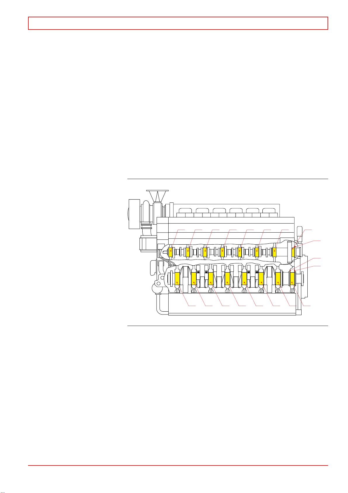
This Manual is supplemented by the Spare Parts Catalogue
including sectional drawings or exterior views of all components
(partial assemblies).
00.2 General rules
1 Read the corresponding item carefully in this Manual
before any steps are taken.
2 Keep an engine log book for every engine.
3 Observe the utmost cleanliness and order at all main-
tenance work.
4 Before dismantling, check that all systems concerned are
drained or the pressure released. After dismantling, immedi-
ately cover holes for lubricating oil, fuel oil and air with tape,
plugs, clean cloth or the like.
32-200328-03 Contents, Instructions, Terminology 00
WÄRTSILÄ 32 00 - 1

5 When replacing a worn-out or damaged part provided
with an identification mark stating cylinder or bearing num-
ber, mark the new part with the same number on the same
spot. Every exchange should be entered in the engine log and
the reason should be clearly stated.
6 After reassembling, check that all screws and nuts are
tightened and locked, if necessary.
7 Check that all shields and covers are fully functional
and in place.
Note! Predictive maintenance is important when it comes to fire
protection. Regular inspection of fuel oil lines, lubricating oil
lines and connections must be done.
00.3 Terminology
The most important terms used in this manual are defined as
follows, see also Fig 00-1:
Operating side. The longitudinal side of the engine where the
operating devices are located (start and stop, instrument panel,
speed governor).
Rear side. The longitudinal side of the engine opposite the
manoeuvering side.
Driving end. The end of the engine where the flywheel is located.
Free end. The end opposite the driving end.
Designation of cylinders. According to ISO 1204 and DIN 6265
the designation of cylinders begins at the driving end. In a
V-engine the cylinders in the left bank, seen from the driving end,
are termed A1, A2 etc. and in the right bank B1, B2 etc., see below:
Terminology
Driving end
Free end
A6 A5 A4 A3 A2
A1
B6 B5 B4 B3 B2 B1
1
2
4
5
63
Operating side
Fig 00-1 WV00519326
00 Contents, Instructions, Terminology 32-200328-03
00 - 2 WÄRTSILÄ 32

Designation of bearings.
·Main bearings. The shield bearing (nearest the flywheel) is No.
0, the first standard main bearing is No. 1, the second No. 2 etc.
·The thrust bearing rails are located at the shield bearing.
The outer rails close to the flywheel are marked with 00 and
the inner rails with 0.
·The camshaft bearings are designated as the main bearings,
the thrust bearing bushes being designated 00 (outer) and 0.
·Camshaft gear bearings. The bearing bushes are designated
00 (outer) and 0.
·Upper and lower bearings shells. In bearings where both the
shells are identical, the upper one is marked with “UP”.
Designation of bearings
Operating side and rear side. Details located at the operating
side may be marked with “M” (Manoeuvering) and correspond-
ingly “B” for the back of the engine (B-bank on a V-engine).
Clockwise rotating engine. When looking at the engine from
the driving end the shaft rotates clockwise.
Counter-clockwise rotating engine. When looking at the
engine from the driving end the shaft rotates counter-clockwise.
Bottom dead centre, abbreviated BDC, is the bottom turning
point of the piston in the cylinder.
Top dead centre, abbreviated TDC, is the top turning point of
the piston in the cylinder. TDC for every cylinder is marked on
the graduation of the flywheel. During a complete working cycle,
comprising in a four-stroke engine two crankshaft rotations, the
piston reaches TDC twice:
01234567
00
0
00
0234567 1
Fig 00-2 4000019601
32-200328-03 Contents, Instructions, Terminology 00
WÄRTSILÄ 32 00 - 3

a) For the first time when the exhaust stroke of the previous
working cycle ends and the suction stroke of the following one
begins. Exhaust valves as well as inlet valves are then somewhat
open and scavenging takes place. If the crankshaft is turned to
and fro near this TDC, both exhaust and inlet valves will move,
a fact that indicates that the crankshaft is near the position which
can be named TDC at scavenging.
b) The second time is after the compression stroke and before the
working stroke. Slightly before this TDC the fuel injection takes
place (on an engine in operation) and this TDC can therefore be
defined TDC at firing. Characteristic is that all valves are closed
and do not move if the crankshaft is turned. When watching the
camshaft and the injection pump it is possible to note that the
pump tappet roller is on the lifting side of the fuel cam.
Marking of the flywheel. The flywheel is divided in 360°, starting
from TDC at firing for cylinder 1. TDC at firing for every cylinder
is marked on the flywheel. There is a common marking for the
cylinders in engines with even cylinder numbers, one cylinder is
at TDC at firing and the other is at TDC at scavenging. There are
separate scales for A- and B-bank in a V-engine. See also the firing
order in chapter 01. Firing interval, in crank angles, can be
determined by dividing 720° with the number of cylinder.
Example of reading the flywheel
Example: On a 12V32 engine, the fuel timing is read to 10° for
cylinder A2 when the flywheel is in the position shown in the above
figure.
55443 3221 10
60
110
Clockwise rotating engine
130
80 120 CYL A2, 5 TDC
70
10˚
Cyl A2 TDC
140
90
Fig 00-3 4000029706
00 Contents, Instructions, Terminology 32-200328-03
00 - 4 WÄRTSILÄ 32

00A. Risk Reduction
00A.1 General
Read the engine manual including this appendix before installing,
operating or servicing the engine and/or related equipment.
Failure to follow the instructions can cause personal injury, loss of life
and/or property damage.
Proper personal safety equipment, e.g. gloves, hard hat, safety
glasses and ear protection must be used in all circumstances.
Missing, imperfect or defective safety equipment might cause seri-
ous personal injury or loss of life.
This appendix contains listed general identified hazards, hazardous
situations or events, which are to be noticed during normal opera-
tion and maintenance work.
Identified hazard,hazardous situation or
event Chapter of engine manual
3 4 8 1011121314151617181920212223
Dropping parts during maintenance work x x x x x x x x x x x x x x x
Turning device engaged during maintenance
work 1) xx xxxxx x
Crankcase safety expl. valves will open if crank-
case explosion xx x
Noiselevel xx xxxxxxxxxxxxxx
Running engine without covers x x x x x x x x x x
In case of major failure, risk of ejected parts x x x x x x x x
Contact with electricity during maintenance
work if power not disconnected x x xx xxx
Electrical hazard if grounding of electrical equip-
ment is incorrect xx x xx
Ejection of components / high pressure gas due
to high firing pressures xx xxx x x
Risk of ejected parts due to break down of turbo-
charger xx
Overspeed or explosion due to air-gas mixture in
the charge air 2) xx x
Ejection of fuel injector if not fastened and crank-
shaft is turned xxx
Engine rotating due to engaged gear box or
closed generator breaker during overhaul xx xxxxx x
Fire or explosion due to leakage on fuel / gas line
or lube oil system xx xxx x
Inhalation of exhaust gases due to leakage 3)
Continues xxx
200343 Risk Reduction Appendix A
00A - 1

Identified hazard,hazardous situation or
event Chapter of engine manual
3 4 8 1011121314151617181920212223
Inhalation of exhaust gas dust x x x x x x x
Explosion or fire if flammable gas/vapour is leak-
ing into the insulation box. 4) xx
Touchingofmovingparts xxxxxxxxxxxx xxx
Highpressurehoses,riskofoilspray. xxxxxxxxxx xx xx
1) Warning light when turning device engaged.
2) Suction air to be taken from gas free space.
3) Require proper ventilation of engine room/plant.
4) Require proper ventilation and/or gas detector in the engine.
00A.1.1 General identified hazards, hazardous situ-
ations or events
00A.1.1.1 Hazards that may be due to moving parts
·Running engine without covers, coming in contact with mov-
ing parts,
·Touching pump parts during unintentional start of el. driven
pump motor,
·Charger starts to rotate due to draft if not locked during
maintenance,
·Somebody sticks his hand into the compressor housing when
the silencer is removed and engine running,
·Unexpected movement of valve or fuel rack(s) due to broken
wire or soft / hardware failure in the control system,
·Unexpected movement of components,
·Turning device engaged during maintenance work,
·Turning device not engaged e.g. Turning device removed for
overhaul, during maintenance work could cause rotating
crankshaft,
·Mechanical breakage (of e.g. speed sensor) due to erratic
actuator assembly to engine or electrical connections.
00A.1.1.2 Hazards that may be due to incorrect operating con-
ditions
·Overspeed or explosion due to air-gas mixture in the charge
air,
·Overspeeding due to air-oil mist mixture in the charge air,
·Malfunction of crankcase ventilation,
·Oil mist detector will trip if water is present in lubricating oil,
Appendix A Risk Reduction 200343
00A - 2

·Crankcase explosion if oil mist is mixed with “fresh” air during
inspection after an oil mist shut down,
·Crankcase safety explosion valves will open if there is a crank-
case explosion.
00A.1.1.3 Hazards that may be due to different leakages, break-
down or improper assembly of component
·Fuel or gas pipe will burst and spray fuel / gas,
·Leakage of:
—fuel in joints on low and/or high pressure side,
—lube oil,
—high pressure water on DWI engines,
—HT water,
—charge air,
—exhaust gas,
—pressurised air from air container, main manifold or pipes,
—high pressure gas and sealing oil on GD engines,
·Fire or explosion due to leakage on fuel line,
·Fire due to oil or fuel / gas leakage,
·Explosion or fire if flammable gas/vapour is leaking into the
insulation box,
·Inhalation of exhaust gases or fuel gases due to leakage,
·Failure of pneumatic stop,
·Ejected components due to:
—breakdown of hydraulic tool,
—breakdown of hydraulic bolt,
—breakdown of turbocharger,
—high firing pressures,
—major failure,
·Ejection of:
—pressurised liquids and gases from the block and pipings,
—high pressure fluid due to breakdown of hydraulic tool,
—gas due to high firing pressures,
—pressurised gases from high pressure gas system,
—high pressure fluid due to breakdown of HP sealing oil pipe,
—high pressure air during maintenance of oil mist detector main
air supply piping,
—cooling water or fuel/lube oil if sensor is loosened while the circuit
is pressurised,
—springs during maintenance work,
·Oil spray if running without covers,
·Ejection of fuel injector if not fastened and
—turning device engaged and turned.
—engine turning due to closed generator breaker/coupling
200343 Risk Reduction Appendix A
00A - 3

00A.1.1.4 Hazards that may be due to electricity or incorrect
connections of electricity
·Fire or sparks due to damage or short circuit in electrical
equipment,
·Contact with electricity during maintenance work if power not
disconnected,
·Electrical hazard if grounding of electrical equipment is incor-
rect,
·Electrical shock if electrical equipment has a lead isolation
break or connector damage or is dismantled with power
connected,
·Overheating of control system component due to erratic elec-
trical connections,
·Incorrectly wired or disconnected emergency stop switch,
·Overload of control system components due to damaged
control circuitry or incorrect voltage,
·Engine not controllable if failure in the shutdown circuitry,
·Unexpected start up or overrun,
·Crankcase explosion if:
—engine not safeguarded at high oil mist levels, due to energy
supply failure,
—engine not (fully) safeguarded at high oil mist levels, due to failure
in oil mist detector circuitry,
—engine not (fully) safeguarded at high oil mist levels, due to
erratic electrical connector or leakage in pipe connection.
00A.1.1.5 Other hazards and hazardous situations where it’s es-
pecially important to use personal safety equipment
·Slip, trip and fall,
·Water additives and treatment products (see appendix 02A,
section 02A.4),
·Touching the insulation box, turbo-charger, pipes exhaust
manifold or (other) unprotected parts without protection dur-
ing engine operation,
·Dropping parts during maintenance work,
·Starting maintenance work too early i.e. causing risk when
handling hot components,
·Neglecting use of cranes and/or lifting tools,
·Not using proper tools during e.g. maintenance work,
·Contact with fuel oil or oily parts during maintenance work
(see appendix 02A),
·Noise level,
·Touching or removing Turbocharger insulation,
·Preloaded fixation springs during check / replacement of
sensor.
Appendix A Risk Reduction 200343
00A - 4

00B. Welding Precautions
00B.1 General Precautions
00B.1.1 Welding safety
Before start welding, it is important to read welding safety instruc-
tions and that the welder is instructed on its safe use by a qualified
teacher or welder.
00B.1.1.1 Hazards and precautions
Electrical shock can kill
·Insulate welder from workpiece and ground using dry insulation.
Rubber mat or dry wood.
·Wear dry, hole-free gloves. (Change as necessary to keep dry.)
·Do not touch electrically “hot” parts or electrode with bare skin or
wet clothing.
·If wet area and welder cannot be insulated from workpiece with dry
insulation, use a semiautomatic, constant-voltage welder or stick
welder with voltage reducing device.
·Keep electrode holder and cable insulation in good condition. Do not
use if insulation is damaged or missing.
Fumes and gases can be dangerous
·Use ventilation or exhaust to keep air breathing zone clear, comfort-
able.
·Use helmet and positioning of head to minimize fume in breathing
zone.
·Read warnings on electrode container and material safety data
sheet (MSDS) for electrode.
·Provide additional ventilation/exhaust where special ventilation re-
quirements exist.
·Use special care when welding in a confined area.
·Do not weld unless ventilation is adequate.
Welding sparks can cause fire or explosion
·Do not weld on containers which have held combustible materials.
Check before welding.
·Remove flammable materials from welding area or shield from
sparks, heat.
·Keep a fire watch in area during and after welding.
·Keep a fire extinguisher in the welding area.
·Wear fire retardant clothing and hat. Use earplugs when welding
overhead.
200640 Welding Precautions Appendix B
00 - 1

Arc rays can burn eyes and skin
·Select a filter lens which is comfortable for you while welding.
·Always use helmet when welding.
·Provide non-flammable shielding to protect others.
·Wear clothing which protects skin while welding
Confined space
·Carefully evaluate adequacy of ventilation especially where elec-
trode requires special ventilation or where gas may displace breath-
ing air.
·If basic electric shock precautions cannot be followed to insulate
welder from work and electrode, use semiautomatic, constant-volt-
age equipment with cold electrode or stick welder with voltage
reducing device.
·Provide welder helper and method of welder retrieval from outside
enclosure.
General work area hazards
·Keep cables, materials, tools neatly organized.
·Connect work cable as close as possible to area where welding is
being performed. Do not allow alternate circuits through scaffold
cables, hoist chains, or ground leads.
·Use only double insulated or properly grounded equipment.
·Always disconnect power to equipment before servicing.
Gas cylinders
·Never touch cylinder with the electrode.
·Keep cylinder upright and chained to support
Appendix B Welding Precautions 200640
00 - 2

00B.1.2 Main principles:
·Prevent uncontrolled current loops
·Prevent radiation
·Prevent sparkles flying around
·If convenient, disconnect all global signals like power supply, data
communication etc.
00B.1.2.1 Preventing uncontrolled current loops
Welding current path must always be checked, there should be a
straight route from the welding point back to the return connection
of the welding apparatus.
The main current is always going where it meets the lowest resis-
tance, in certain cases the return current can therefore go via
grounding wires and electronics in the control system.
To avoid this, the distance between the welding point and the return
connection clamp of the welding apparatus should always be
shortest possible and without electronic components in the return-
ing loop path.
Attention must be paid to the connectivity of the return connection
clamp, a bad contact might also cause sparkles and radiation.
00B.1.2.2 Preventing Radiation
The welding current and the arc is emitting a wide spectrum of
electromagnetic radiation. This might cause damages on sensitive
electronic equipment.
To avoid these damages all cabinets and terminal boxes must be
kept closed during the welding. Sensitive equipment can also be
protected by means of shielding with a conductive metal plate.
Also avoid having the cables of the welding apparatus going in
parallel with wires and cables in the control system. The high welding
current is easily inducting secondary currents in other conductive
materials.
00B.1.2.3 Preventing damage due to sparkles
Welding produces sparks. Few materials withstand the heat from
these sparkles. Therefore all cabinets and terminal boxes should be
kept closed during the welding. Sensors, actuators, cables and
other equipment on the engine must be properly protected.
Sparkles can also be a problem after they have cooled down, i.e.
causing short circuits, sealing problems etc.
200640 Welding Precautions Appendix B
00 - 3

00B.2 Precaution checklists
00B.2.1 Basic ECU (Despemes/Spemos) checklist
The following precautions must be paid attention to before welding
in the vicinity of a basic ECU system:
·Close the cover of the cabinet
·Deactive the system by disconnecting all external connectors
(X1...X4).
·If convenient, protect cables, sensors and other equipment from
sparkles with a proper metal sheet.
00B.2.2 WECS 2000 checklist
The following precautions must be paid attention to before welding
in the vicinity of a WECS 2000 control system:
·Open all terminal fuses (F1- FX) in the cabinet.
·Close the covers of the cabinet and all the distributed units.
·Deactivate the system by disconnecting all external connectors
(X1...X6).
·If convenient, protect cables, sensors and other equipment from
sparkles with a proper metal sheet.
00B.2.3 WECS 3000 checklist
The following precautions must be paid attention to before welding
in the vicinity of a WECS 3000 control system:
·Deactive the system by disconnecting all external connectors
(X1...X5).
·Do not connect the welding apparatus return line to the aluminium
profile containing CCU’s, KDU’s and ignition modules. The profile is
used as a common ground for these modules.
·Open all terminal fuses (F1...F20) in the cabinet.
·Close the covers of the cabinet and all the distributed units.
·If convenient, protect cables, sensors and other equipment from
sparkles with proper metal sheet.
00B.2.4 WECS 7000/8000 checklist
The following precautions must be paid attention to before welding
in the vicinity of a WECS 7000 or 8000 control system:
·Deactive the system by disconnecting all external connectors
(X1...X6).
·If the welding point is close to (approximately within a radius of 2 m)
an electronic module disconnect all connectors of the unit.
Appendix B Welding Precautions 200640
00 - 4

·If an electronic module is connected through a CIB (Connection
Interface Box) then open the CIB cover and disconnect all connec-
tors of the unit and close cover again.
·Close the covers of the cabinet
·If engine equipped with harness: Disconnect the interconnections
between the harnesses and the cabinet.
·If convenient, protect harnesses, cables, sensors and other equip-
ment from sparkles with a proper metal sheet.
00B.2.5 UNIC Precautions checklist
The following precautions must be paid attention to before welding
in the vicinity of a UNIC control system:
·Deactivate the system by disconnecting all external connectors from
the PDM-10 or PDM-20 (X11, X12) and from the external interface
connectors (XM#).
·If the welding point is close to (approximately within a radius of 2 m)
an electronic module (IOM-10, MCM-10, CCM-20 etc.) disconnect
all connectors of the unit
·Close the covers of the cabinet and all the distributed units.
·If convenient, protect cables, sensors and other equipment from
sparkles with a proper metal sheet.
200640 Welding Precautions Appendix B
00 - 5

Appendix B Welding Precautions 200640
00 - 6

01. Main Data, Operating Data and
General Design
01.1 Main data for Wärtsilä 32
Cylinder bore . . . . . . . . . . . . . . . . . . . . . . . . . . . . . . . . . 320 mm
Stroke . . . . . . . . . . . . . . . . . . . . . . . . . . . . . . . . . . . . . . . 400 mm
Piston displacement per cylinder. . . . . . . . . . . . . . . . . . 32.17 l
Firing order
Engine type Clockwise rotation Counter-clockwise rotation
6L32 1-5-3-6-2-4 1-4-2-6-3-5
8L32 1-3-7-4-8-6-2-5 1-5-2-6-8-4-7-3
9L32 1-7-4-2-8-6-3-9-5 1-5-9-3-6-8-2-4-7
12V32 A1-B1-A5-B5-A3-B3-
A6-B6-A2-B2-A4-B4 A1-B4-A4-B2-A2-B6-
A6-B3-A3-B5-A5-B1
16V32 A1-B1-A3-B3-A7-B7-A4-B4-
A8-B8-A6-B6-A2-B2-A5-B5 A1-B5-A5-B2-A2-B6-A6-B8-
A8-B4-A4-B7-A7-B3-A3-B1
18V32 A1-B1-A7-B7-A4-B4-A2-B2-A8-
B8-A6-B6-A3-B3-A9-B9-A5-B5 A1-B5-A5-B9-A9-B3-A3-B6-A6-
B8-A8-B2-A2-B4-A4-B7-A7-B1
20V32 A1-B1-A4-B4-A3-B3-A2-B2-A6-
B6-A10-B10-A7-B7-A8-B8-A9-
B9-A5-B5
A1-B5-A5-B9-A9-B8-A8-B7-A7-
B10-A10-B6-A6-B2-A2-B3-A3-
B4-A4-B1
Normally the engine rotates clockwise.
Lubricating oil volume in the engine
Engine type 6L32 8L32 9L32 12V32 16V32 18V32
App. oil volume in litres
Wet sump 1630 2050 2270 3050 3860 4270
Oil volume between
max. and min. marks
appr. litres/mm
2.95 3.70 4.05 4.25 5.35 5.90
Lubricating oil volume in the turning device in litres
LKV132 8.5 - 9.5
Lubricating oil volume in the speed governor in litres
1.4 - 2.2 1)
1) The lubricating oil volym is depending of the governor type. See
manufacturers instruction.
App. cooling water volume in the engine in litres
Engine type 6L32 8L32 9L32 12V32 16V32 18V32
Engine only 410 510 560 740 840 890
32-200634-01 Main Data, Operating Data and General Design 01
WÄRTSILÄ 32 01 - 1

01.2 Recommended operating data
Apply to normal operation at nominal speed. See also installation
specific Modbus list.
Normal values Alarm (stop) limits
Load 100 % 0 - 100 %
Temperatures, (°C)
Lube oil before engine 60-65 75 (80) (2)
Lube oil after engine 10 - 13
higher
HT water after engine 91 - 96(1) 105 (110) (2)(3)
HT water before engine 5 - 8 lower 50
HT water rise over turbocharger (xx) 8 - 12
LT water before charge air cooler 28 - 38 45 (60)(5)
Charge air in air receiver 50 - 60 75
Exhaust gas after cylinder See test records 500 (520) (2)
Exhaust gas before turbocharger ¾
Preheating of HT water 50 (MDO) 70 (HFO) 45
Cylinder liner temp. 130 - 150 160 (180)(2)
Main bearing temp. 90 - 100 110 (120)(2)
Gauge pressures (bar)
Lube oil before engine at a speed
of 600 RPM (10.0 r/s) 4.5 3.0 (2.0)
720 RPM (12.0 r/s) - 750 RPM
(12.5 r/s) 5.0 - 5.5 3.0 (2.0)
HT/LT water before HT/LT pump
(=static) 0.7 - 1.5
HT water before engine 2.5 + static press.(1) 1.5 + static press. (2) (2) (4)
LT water before charge air cooler 2.5 + static press. (1) 1.5 + static press.
Fuel before engine 7 -8 (HFO/LFO) 4
Fuel before engine, Common Rail 11 -12 (HFO/LFO) 4
Compressed air (start & control air) max. 30 18
Charge air (CAC, outlet) See test records 3
Other pressures (bar)
CAC, pressure difference 75 mbar
Crankcase pressure 3 mbar
Firing pressure See test records
Opening pressure of safety valve on
lube oil pump 6 - 8
Lube oil filter pressure difference 0.8 - 1.8 0.8 (first) 1.8 (second alarm)
(1) Depending on speed and installation
(2) Load reduction, main engine
(3) Stop, auxiliary engine
(4) Stop, on GL installation, main engine
(xx) When water cooled turbocharger
(5) Only in special conditions
01 Main Data, Operating Data and General Design 32-200634-01
01 - 2 WÄRTSILÄ 32
This manual suits for next models
1
Table of contents
Other WÄRTSILÄ Engine manuals

WÄRTSILÄ
WÄRTSILÄ WARTSILA 20 User manual

WÄRTSILÄ
WÄRTSILÄ WARTSILA 26 User manual

WÄRTSILÄ
WÄRTSILÄ WARTSILA 50DF User manual

WÄRTSILÄ
WÄRTSILÄ AL20 Assembly instructions

WÄRTSILÄ
WÄRTSILÄ WARTSILA32 User manual

WÄRTSILÄ
WÄRTSILÄ 41508 User manual

WÄRTSILÄ
WÄRTSILÄ 34DF Series User manual

WÄRTSILÄ
WÄRTSILÄ 46DF User manual

WÄRTSILÄ
WÄRTSILÄ W-X62 User manual

WÄRTSILÄ
WÄRTSILÄ WARTSILA 34DF User manual