/
/
✓
ENGLISCH
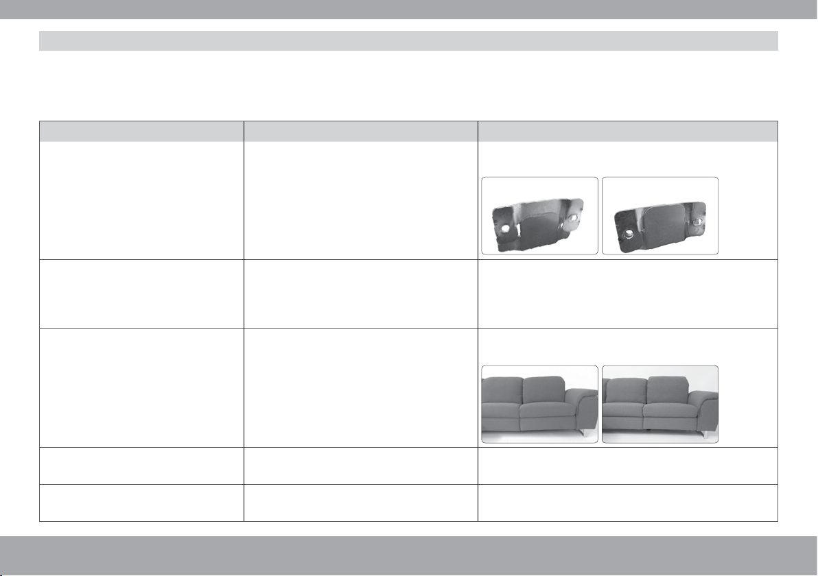
Occurring fault Check Possible remedy
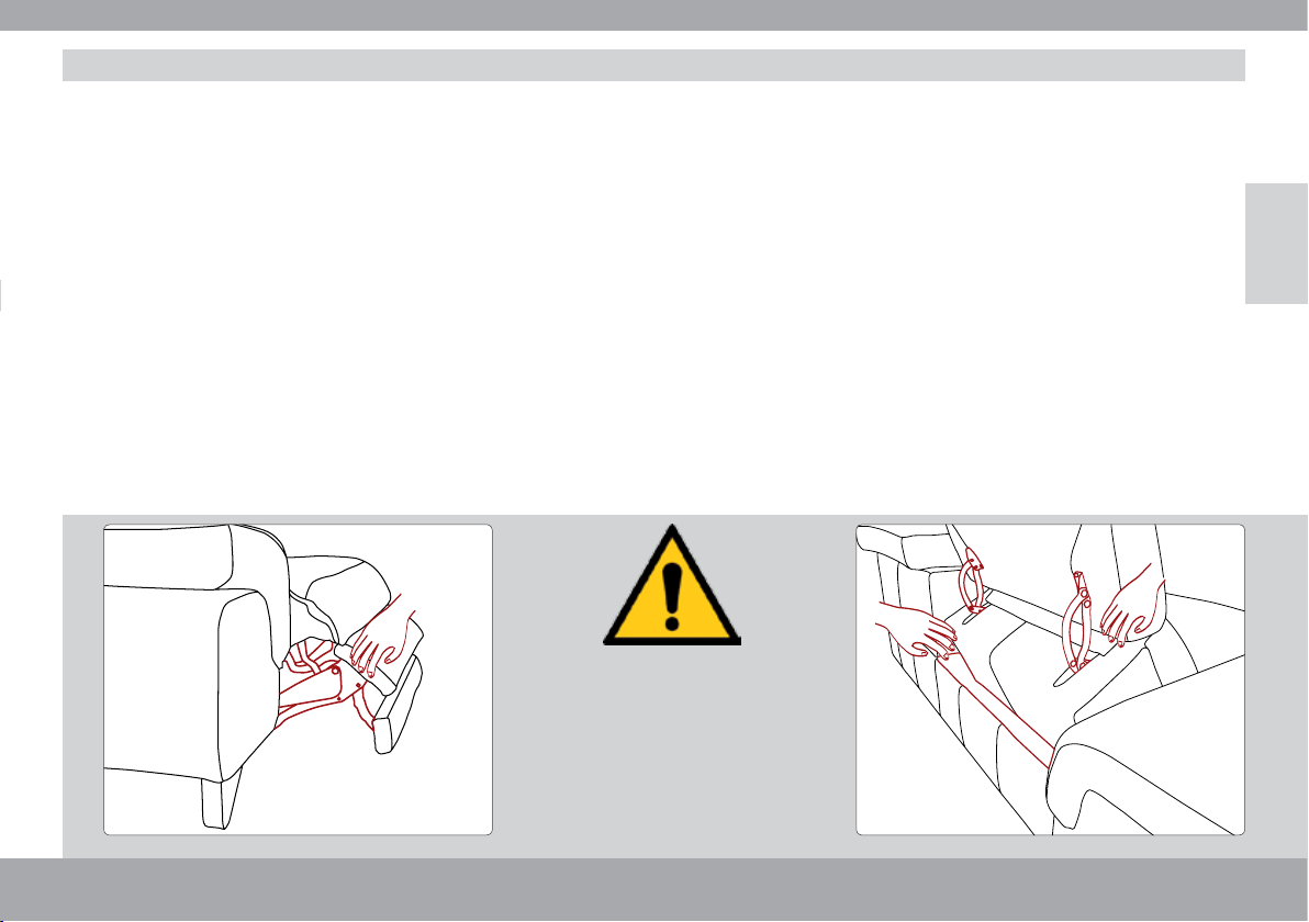
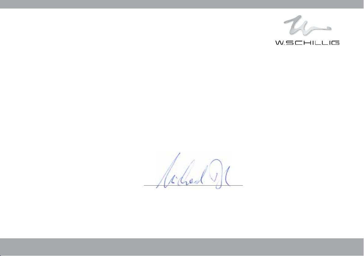
The foot rests are not flush with each
other when extended.
Observe clean mounting of the individual
function elements.
Install the function elements so that the frames are placed
to form one surface at the lower edges.
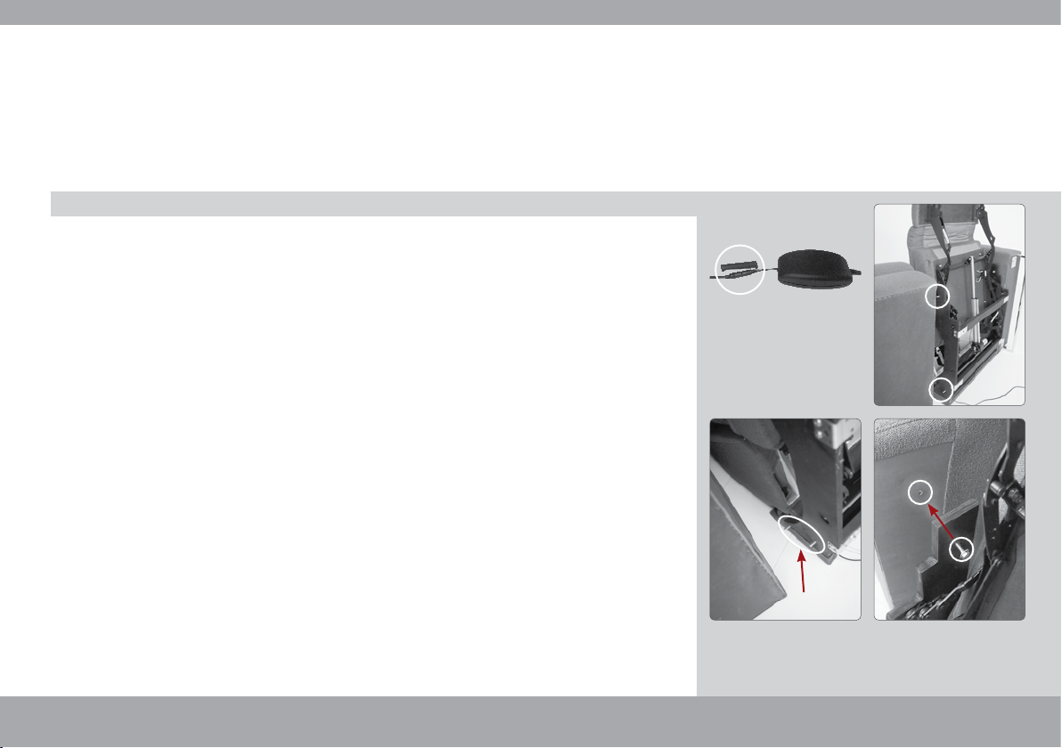
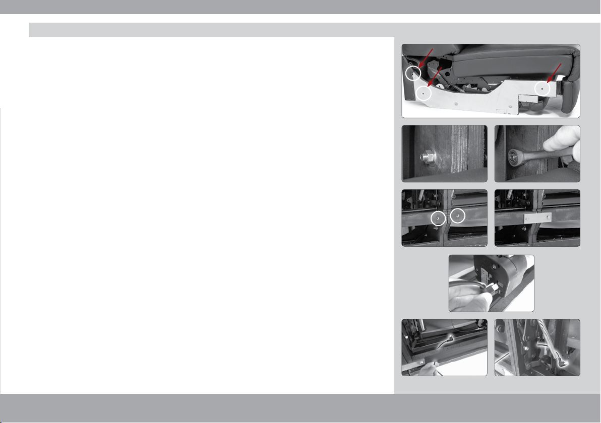
The motor-powered seat/backrest ad-
justment does not work.
1. Mains unit plug not in the socket. Insert the plug into the socket.
2. The cable from the mains unit to the motor
is not connected to the mains unit.
Connect the plugs.
3. Check plug connections of the cable from
the control (under the seat on the left) to
the motor.
Connect the plugs (modular plug, four-pin) to the control
and motor.
4. Plug of sensor buttons not connected to
the control (under the seat on the left).
Connect plug (jack plug) into the control.
RED – rear direction of backrest
BLACK – forward direction of backrest.
Please only clean the operating elements with a dry, soft and clean cloth. Check the joints of the fittings for cleanliness now and then. General
cleaning of the joints is recommended. Since functional furniture is exposed to regular movement processes, metal abrasion may occur under the
furniture. Please remove it regularly by vacuuming or sweeping.
For individual notes on your reference material, see the respective care set.
Since we are committed to the environment, we ask you to dispose of your furniture professionally after the end of its use! The drive system,
of your motor-powered furniture contains electronic components. They are to be disposed of according to the currently valid environmental
provisions of the respective country. For this, please contact the municipal offices. The packaging material used at delivery is recyclable as well.
Dispose of the materials in the intended collection systems sorted by type.
Care notes
Disposal
–19––18–