WACO YMF F5 Series User manual

YMF WACO F5 SERIES
MAINTENANCE MANUAL
YMFAMM-1

WACO Classic Aircraft Corporation
YMF WACO F5 SERIES MAINTENANCE MANUAL
REVISION: H Page
1
of
33
RELEASED: 07/21/2017 PART NO. YMFAMM-1
SECTION 1 RECORD of REVISIONS
1.1 REVISION LOG
LTR.
DATE
DESCRIPTION
PAGES AFFECTED
E
05/10/2010
Complete rewrite, reformatted, all pages.
1 through 31
F
02/08/2013
Sec. 7 Paragraph 7.2(c) Revised. Fig. 7.2 Added.
Paragraph 7.4 added.
New number of pages is 33.
2,23,24,28
G
06/20/2016
Sec. 10 revised. Form F-236 added
33
H
07/21/2017
Sec. 7 revised. Fig. 4 added
Sec. 10 revised
30
33
Note:
Newly revised material is identified by a vertical line in the left margin of the paragraph of text affected.

WACO Classic Aircraft Corporation
YMF WACO F5 SERIES MAINTENANCE MANUAL
REVISION: H Page
2
of
33
RELEASED: 07/21/2017 PART NO. YMFAMM-1
SECTION 2 CONTENTS
2.1 TABLE of CONTENTS
SECTION 1 RECORD of REVISIONS.................................................................................... 1
1.1 REVISION LOG.......................................................................................................... 1
SECTION 2 CONTENTS........................................................................................................ 2
2.1 TABLE of CONTENTS................................................................................................ 2
SECTION 3 DEFINITIONS..................................................................................................... 4
3.1 TERMS:...................................................................................................................... 4
3.2 SPECIAL INSTRUCTIONS:.................................................................................... 4
3.3 SERVICE LETTERS:.......................................................................................... 4
3.4 SERVICE INSTRUCTIONS:............................................................................ 4
SECTION 4 INTRODUCTION ................................................................................................ 5
4.1 INSTRUCTIONS FOR CONTINUED AIRWORTHINESS:........................................... 5
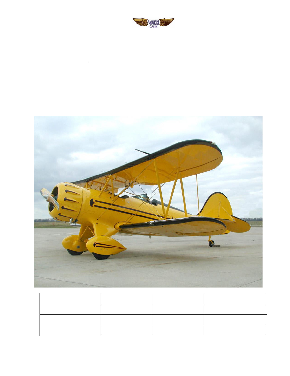
SECTION 5 GENERAL:.......................................................................................................... 6
5.1 DESCRIPTION:.......................................................................................................... 6
5.2 SPECIFICATIONS:......................................................................................................... 7
5.2.1 MODEL DESIGNATIONS:.......................................................................................... 7
5.2.2 DIMENSIONS:........................................................................................................ 7
5.2.3 FLUID CAPACITIES:.......................................................................................... 8
5.2.4 FLUID GRADES: ............................................................................................ 8
5.3 GROUND HANDLING.................................................................................................... 8
5.3.1 MOVING:.................................................................................................................... 8
5.3.2 TAXIING:................................................................................................................... 9
5.3.3 PARKING:............................................................................................................11
5.3.4 MOORING..........................................................................................12
5.3.5 JACKING:.........................................................................................................12
WEIGHING THE AIRPLANE .....................................................................................12
5.3.6 CARE OF THE AIRPLANE.........................................................................14
SECTION 6 AIRFRAME........................................................................................................15
6.1 FUSELAGE...............................................................................................................15
6.2.1 INSPECTION PERIODS........................................................................................15
6.2 LANDING GEAR................................................................................................19
6.3 EMPENAGE...................................................................................................20
6.4 WINGS.......................................................................................................21
SECTION 7 POWERPLANT..................................................................................................23
7.1 ENGINE COWLS.......................................................................................................23
7.2 ENGINE REMOVAL & INSTALLATION.................................................................23
7.4 COMPRESSION TESTING OF ENGINE CYLINDERS:.....................................28
PROPELLER INSTALLATION...................................................................................29
SECTION 8 SYSTEMS..........................................................................................................31
8.1 GASOLINE SYSTEM.................................................................................................31
8.2 OIL SYSTEM.........................................................................................................31
8.3 ELECTRICAL SYSTEM.....................................................................................31
SECTION 9 AIRWORTHINESS LIMITATIONS .....................................................................32
9.1 APPLICABILITY ........................................................................................................32
SECTION 10 MISCELLEOUNEOUS MAINTENANCE INFORMATION...............................33
A. WCAC FORM SMWS SCHEDULED MAINTENANCE WORKSHEET...........................33

WACO Classic Aircraft Corporation
YMF WACO F5 SERIES MAINTENANCE MANUAL
REVISION: H Page
3
of
33
RELEASED: 07/21/2017 PART NO. YMFAMM-1
B. WIREING DIAGRAMS...................................................................................................33
C. JACOBS OPERATORS MANUAL MODELS R-755A2 7 R-755B2 ................................33
D. SENSENICH PROPELLER CO. INSTALLATION AND MAINTENANCE INSTRUCTIONS........33
E. MT-PROPELLER INSTALLATION AND MAINTENANCE MODEL MT233R150-6AJ....33
F. HAMILTON STANDARD MODEL 2B20 CONSTANT SPEED PROPELLER INSTRUCTIONS...33
G. BENDIX BATTERY IGNITION SERVICE INSTRUCTIONS AND PARTS LIST .............33
H. BENDIX-SCINTILLA AIRCRAFT MAGNETOS SERVICE INSTRUCTIONS..................33
I. SIGTRONICS (JASCO) ALTERNATOR TROUBLE SHOOTING INFORMATION.........33
J. BRACKET AIR FILTER INSTRUCTIONS FOR CONTINUED AIRWORTHINESS.........33
K. PARKER HANNIFIN WHEEL AND BRAKE MAINTENANCE PROCEDURES ..............33
L. SERVICE LETTERS and SERVICE BULETINS............................................................33
M, K&L SOARING FORM F-236 ........................................................................................33
N. MT-PROPELLER INSTALLATION AND MAINTENCE MODEL MTV-15-AA-C/C-236-29............33

WACO Classic Aircraft Corporation
YMF WACO F5 SERIES MAINTENANCE MANUAL
REVISION: H Page
4
of
33
RELEASED: 07/21/2017 PART NO. YMFAMM-1
SECTION 3 DEFINITIONS
3.1 TERMS:
Aeronautical terms used in this manual are as defined in CFR Title 14 Part 1, "Definitions and
Abbreviations". Other terms used are defined as follows:
3.2 SPECIAL INSTRUCTIONS:
Information or instructions considered to be of special significance are annotated as shown
below:
(a) NOTE: - Used to call attention to information or instructions of an advisory nature only. This
information is enclosed in a box as shown below:
NOTE
(b) CAUTION: - Used to call attention to information or instructions which, if not followed, could
lead to a non-airworthy condition or result in the airplane being operated outside of it's Approved
Limits. This information is enclosed in a box as shown below:
CAUTION
(c) WARNING: - Used to call attention to information or instructions which, if not followed, would
result in a non-airworthy condition. This information is enclosed in a box as shown below:
WARNING
3.3 SERVICE LETTERS:
Service Letters are issued by WACO Classic Aircraft Corporation as needed to provide
additional maintenance information not included in the current revised maintenance manual or
to alert owners and operators of service issues that if unaddressed could lead to an un-
airworthy condition. Compliance with Service Letters is not mandatory but is strongly advised to
insure the continued airworthiness of the affected aircraft. WACO Classic Aircraft will make
every reasonable effort to make Service Letters available to all owners of record.
3.4 SERVICE INSTRUCTIONS:
Service Instructions are provided as needed to assist maintenance personnel with the
installation of Service Kits or when a replacement part or assembly has been changed in such a
way as to require additional information not included in the current revised Maintenance Manual.

WACO Classic Aircraft Corporation
YMF WACO F5 SERIES MAINTENANCE MANUAL
REVISION: H Page
5
of
33
RELEASED: 07/21/2017 PART NO. YMFAMM-1
SECTION 4 INTRODUCTION
4.1 INSTRUCTIONS FOR CONTINUED AIRWORTHINESS:
In accordance with Federal Aviation Regulations (FAR) Part 23, Appendix G, this Maintenance
Manual constitutes the Instructions for Continued Airworthiness for the YMF WACO F5 series aircraft
manufactured by WACO Classic Aircraft Corporation and its predecessor Classic Aircraft Corporation and
supersedes previous editions of the WACO Classic Service Manual as revised March 13, 2006 which is
obsolete.

WACO Classic Aircraft Corporation
YMF WACO F5 SERIES MAINTENANCE MANUAL
REVISION: H Page
6
of
33
RELEASED: 07/21/2017 PART NO. YMFAMM-1
SECTION 5 GENERAL:
5.1 DESCRIPTION:
The WACO Classic Aircraft YMF WACO F5 series aircraft is a single engine, three place, open bi-plane
seating two passengers in the front cockpit and a single pilot in the rear and having a conventional
landing gear arrangement. The fuselage frame and tail surfaces are constructed of TIG welded 4130 steel
tubing and the wings of premium aircraft grade Sitka spruce with 4130 steel fittings throughout. The
fuselage frame is fitted with mahogany plywood formers and spruce stringers to give it shape. The entire
aircraft is covered with Ceconite (Polyfiber) 102 Dacron fabric and finished according to WACO Classic
Process Specifications with the standard finish color being PPG Urethane enamel. All models are
equipped with a Jacobs 7 cylinder radial engine either carburetor or fuel injection equipped and with
either a fixed pitch or constant speed propeller.
The following table lists the various models of the series.
MODEL DESIGNATION
SERIAL NUMBERS
MAXINUM GROSS
WEIGHT
MODEL YEAR
YMF WACO F5A
F5001 THRU F5009
2650 Pounds
1986 to1987
YMF WACO F5B
F5010 THRU F5O36
2770 Pounds
1987to1991
YMF WACO F5C
F5C040 and Up
2950 Pounds
1991 and On

WACO Classic Aircraft Corporation
YMF WACO F5 SERIES MAINTENANCE MANUAL
REVISION: H Page
7
of
33
RELEASED: 07/21/2017 PART NO. YMFAMM-1
5.2 SPECIFICATIONS:
All models are manufactured in conformance with FAA Type Certificate Number ATC542 and
Supplemental Type Certificate Number SA1000GL the details of which can be found by accessing the
Type Certificate Data Sheet (TCDS) for the WACO Aircraft Company YMF at www.faa.gov. Although a
summary of specifications is given here, the TCDS should always be consulted when making conformity
determinations.
5.2.1 MODEL DESIGNATIONS:
Although Type Certificate Data Sheet ATC542 lists this series simply as the Model YMF F5 modification,
modified by STC SA1000GL, for the purpose of clearly identifying to which aircraft an instruction or
reference applies, the following model designations are used in this manual.
Model YMF WACO F5A (Approved March 10, 1986):
This model is the first of the series manufactured by Classic Aircraft Corporation of Lansing MI having a
maximum gross takeoff weight of 2650 pounds, a Jacobs R755B2 engine and carry serial numbers
F5001 through F5009. Although fitted with a Jacobs R755B2 engine rated at 275 HP at 2200 RPM, this
model airframe is limited by propeller or placard to 245 HP and 1950 RPM at sea level.
CAUTION
ALTHOUGH A VARIETY OF PROPELLERS ARE ELEGIBLE FOR
INSTALLATION ON THIS MODEL, IT SHOULD BE NOTED THAT THE 245
HP LIMITATION CAN BE EXCEEDED WITH A PROPELLER OF LESS
THAN 96 IN. DIAMETER AND LESS THAN 72 IN. PITCH. IT IS THE
OPERATOR’S RESPONSIBILITY TO INSURE THAT THE RPM AND HP
LIMITATION IS NOT EXCEEDED.
Model YMF WACO F5B (Approved January 28, 1988):
This model is the second of the series manufactured by Classic Aircraft Corporation at Lansing MI, has a
maximum gross takeoff weight of 2770 pounds and are identified by serial numbers F5010 through
F5036. This model is fitted with a Jacobs R755B2 engine with a horsepower rating of 275 at 2200 RPM
and is not HP limited.
Model YMF WACO F5C (Approved June 24, 1991):
The F5C is the third model of the series and has been manufactured in both Lansing and Battle Creek MI,
first by Classic Aircraft Corporation and since 1997 by WACO Classic Aircraft Corporation. This version
has a maximum gross takeoff weight of 2950 pounds and is powered by the Jacobs R755B2 engine rated
at 275 HP at 2200 RPM and may be either carburetor or fuel injection equipped.
Model YMF WACO F5C-8 (Approved May 12, 2010):
The F5C-8 is a variation of the F5C with the optional Jacobs R755A2 engine rated at 300 HP at 2200
RPM installed either during manufacture or as a retrofit and may be equipped with either carburetor or
fuel injection. Serial numbers F5C040 and up are eligible for this option and can be identified by a “-8” in
the serial number (example F5C-8-121).
5.2.2 DIMENSIONS:
The general dimensions of the Models F5A and F5B are as follows:
WING SPAN (UPPER) 30 Ft. 0 In. (9.14M)
WING SPAN (LOWER) 26 Ft. 10 In. (8.18M)
LENGTH (OVERALL) 23 Ft. 4 In. (7.11M)
HEIGHT (OVERALL) 8 Ft. 6 In. (2.59M)
The general dimensions of the Model F5C are as follows:
WING SPAN (UPPER) 30 Ft. 0 In. (9.14M)
WING SPAN (LOWER) 26 Ft. 10 In. (8.18M)

WACO Classic Aircraft Corporation
YMF WACO F5 SERIES MAINTENANCE MANUAL
REVISION: H Page
8
of
33
RELEASED: 07/21/2017 PART NO. YMFAMM-1
LENGTH (OVERALL) 23 Ft. 10 In. (7.26M)
HEIGHT (OVERALL) 8 Ft. 6 In. (2.59M)
5.2.3 FLUID CAPACITIES:
FUEL SYSTEM:
All models have a standard fuel system capacity of 48 US Gal. (182 Litre) in two 24 gallon main tanks
located in the center wing section above the front cockpit. One or two optional 12 US Gal. (45 Litre) tanks
may be installed in the upper wings, one left or one right or both left and right, just outboard of the center
wing section. These are connected to and feed directly into the respective adjacent main fuel tank outlet
and cannot be individually selected.
ENGINE OIL SYSTEM:
The Jacobs engine is of the dry sump type with the lubricating oil being contained in a 4 (15 Litre) or 5 (19
Litre) gallon capacity tank mounted aft of the engine and forward of the firewall. The required engine oil
capacity is established by regulation depending on fuel capacity. Airplanes equipped with a standard 48
gallon fuel system may have a 4 gallon oil tank and those with optional auxiliary fuel must have a 5 gallon
oil tank.
HYDRAULIC SYSTEM:
The hydraulic system of all models consists of a hydraulically operated toe brake system. The reservoir is
located on the left side of the engine firewall and has a capacity of approximately one pint.
5.2.4 FLUID GRADES:
FUEL (AVIATION):
All models require 80 Octane Aviation Gasoline minimum grade fuel.
ENGINE OIL:
All models require the use of only aviation grade engine oils, with or without ashless dispersant (AD). It
is recommended that AD type oil be used to reduce sludge buildup. Single grade or multi-grade oils may
be used. If single grade oil is used, the ambient temperature in which the engine will be operated should
be considered as follows:
Ground Temperature Grade of Oil
Above 50 Deg. F (10 Deg. C) 100 Saybolt or SAE 50
50 Deg. F to 20 Deg. F (10 C to -5 C) 80 Saybolt or SAE 40
Below 20 Deg. F (-5 C) 65 Saybolt or SAE 30
In very hot ground conditions or if the inlet oil temperature frequently exceeds 185 Deg. F (85 C), Grade
120 Saybolt (SAE 60) should be used.
HYDRAULIC FLUID:
The hydraulic brake system in all models requires the use of Mil-H-5606 Hydraulic oil (Red) or equivalent.
5.3 GROUND HANDLING
5.3.1 MOVING:
Always disengage the tail wheel steering mechanism before attempting to move the airplane by hand or
by towing. This can be accomplished by moving the tail wheel steering control located on the left side of
the rear cockpit to the forward position.
To move the airplane it is recommended that a suitable tug or tow vehicle be used with a spreader type
tow bar attached to the tow rings provided on the inboard side of each main landing gear axel. An
acceptable alternate method would be the use of a tail wheel type towing device such as the Tail-
Dragger Dragger®. In selecting a tail wheel towing device it is important to insure that it will be low
enough to not come in contact with the rudder when connected, will securely engage the tail wheel or
strut without danger of unwanted disengagement and has the power needed to safely move a 3000
pound airplane considering the surface to be traversed. If no towing device or tug is available, the
airplane can be moved by hand by gripping the front inter-plane strut at its base near the leading edge of
the lower wing. It is recommended that two persons be used for moving by hand, one on each side, and,
if possible, a third person at the tail in front of the horizontal stabilizer gripping the stabilizer spar at the
base of the fin to assist in steering, taking care not to push against the fuselage, fin or stabilizer.

WACO Classic Aircraft Corporation
YMF WACO F5 SERIES MAINTENANCE MANUAL
REVISION: H Page
9
of
33
RELEASED: 07/21/2017 PART NO. YMFAMM-1
5.3.2 TAXIING:
CAUTION
IMPORTANT: GROUND RUN OPERATIONS SHOULD BE
CONDUCTED ONLY BY PERSONNEL PROPERLY
TRAINED AND EXPERIENCED IN THE OPERATION OF
THIS TYPE AIRCRAFT!
Before attempting to taxi the airplane, ground personnel should be instructed and approved by a qualified
person authorized by the owner. Engine starting and shut-down procedures as well as taxi techniques
should be covered.
ENGINE STARTING PROCEDURES:
Before Starting Engine:
(a) Seat - Position and lock
(b) Seat belt and shoulder harness –Fasten
NOTE
For safety it is recommended that the seat belt and
shoulder harness be fastened even for taxi and run-
up operations
(c) Parking brake* - As needed *Refer to parking brake operating instructions below before using!
(d) All electrical switches and avionics - Off
(e) Fuel selectors - Both on
(f) Fuel quantity indicators –Check
Normal Engine Start - Carburetor Equipped:
(a) Battery master switch - On
(b) Light switches - As needed
(c) Ignition switch - "Bat Ign" position ("Off" if dual magnetos are installed)
(d) Mixture control - Full rich (forward position)
(e) Carburetor heat control - Off (forward position)
(f) Propeller control (if Hamilton Standard Propeller installed) - High pitch
(Low RPM) full aft
(g) Throttle lever - Cracked (1/4 inch) open
(h) Engine primer pump - As needed (10 to 12 strokes for cold engine,
(2 or 3 for hot engine)
(i) Starter - Engage
CAUTION
Do not pump the throttle to start. Fuel can collect in the
air inlet and cause a fire hazard. If the engine does not
start immediately, disengage the starter, wait 2 to 3
minutes and repeat the start procedure.
(j) Ignition switch - Both position after engine starts (Both after 2 –3
revolutions if dual mags are Installed)
(k) Primer pump - As needed to keep engine running (cold weather)
(l) Primer pump - Lock closed when no longer needed
(m) Oil pressure - Check (30 PSI min within 15 sec) If no oil pressure within 30 sec shut down and check
for cause.
(n) Propeller control lever (if Hamilton Standard prop installed) - After 30 sec.
Move to full forward position

WACO Classic Aircraft Corporation
YMF WACO F5 SERIES MAINTENANCE MANUAL
REVISION: H Page
10
of
33
RELEASED: 07/21/2017 PART NO. YMFAMM-1
(o) Alternator field switch - On
(p) Avionics master switch - On
(q) Engine warm-up - 600 RPM for 30 seconds after start then 800 to 1000
RPM to warm up
Normal Engine Start Fuel Injection Equipped (Cold):
(a) Mixture control in idle cut-off position
(b) Set throttle to 1/8 open
(c) Master switch - ON
(d) Boost pump switch - ON
(e) Move mixture control to FULL RICH until fuel flow meter reads 4 to 6
GPH then immediately return mixture control to cut-off position
(f) Engage starter. When engine starts, move mixture control to full rich
(g) After start, to verify function of engine driven fuel pump, momentarily
switch boost pump off and watch fuel flow gauge for possible loss of
pressure.
Hot Engine Start Fuel Injection Equipped:
Use the same procedure as for cold starts except that the boost pump
May be left off and step (e) eliminated
Engine Start Using External Power:
CAUTION
The airplane has a negative ground electrical system. Be
sure the positive and negative leads are connected to the
corresponding terminals of the power source. To prevent
arcing at the power plug, no power is to be applied to the
power cable while the connection is being made.
(a) Battery master, avionics, alternator, and all other electrical switches - Off
(b) External power unit - Off and connect
(c) External power unit - Output set to 24 Volts and On
(d) Battery master switch - On
(e) Engine - Start using normal procedures described above
(f) External power unit - Off and disconnect after engine is started
AFTER ENGINE START
(1) Before beginning to taxi, be sure the area in front of the airplane is clear of obstacles. It is advisable
to initiate a slight turn to one side or the other as soon as practical to see this area. Taxi a few feet
forward and apply the brakes to determine their effectiveness.
(2) While taxiing, make slight turns to ascertain the effectiveness of the steering. The tail wheel steering
should be engaged for normal steering, however, it may be disengaged and the brakes and rudder
used to make sharp turns.
(3) Observe wing clearance when taxiing near buildings or other stationary objects keeping in mind that
the upper wings extend beyond the lower wings and the tips cannot be seen from the pilot’s seat. If
possible, station an observer outside the airplane.
(4) When taxiing over uneven ground avoid holes and ruts.
(5) Do not operate the engine at high RPM when running up or taxiing over ground containing loose
stones, gravel or any loose material that may cause damage to the propeller blades. It is also
advisable to not taxi through aircraft tie-down areas except as necessary for parking to avoid the
possibility of striking an unseen parked aircraft or chocks.

WACO Classic Aircraft Corporation
YMF WACO F5 SERIES MAINTENANCE MANUAL
REVISION: H Page
11
of
33
RELEASED: 07/21/2017 PART NO. YMFAMM-1
NOTE
REMEMBER –FORWARD VISIBILITY IS LIMITED.
USE EXTREME CAUTION WHEN TAXIING
5.3.3 PARKING:
*Parking Brake Operating Instructions:
1. To apply the parking brake:
(a) Apply brakes by depressing toe brake pedals
(b) Pull parking brake control "T" handle out
NOTE
Initial brake application pressure should be only enough to
allow the control handle to be pulled out. Keep in mind that to
release the parking brake, more pressure must be applied
than was initially used, and that any brake application while
the control handle is out traps additional pressure in the
system. It is possible to accumulate enough pressure in the
brake system so that the parking brake cannot be released. If
this condition occurs, the pressure must be relieved by
loosing the brake hose fitting at each brake caliper. Retighten
after the parking brake valve has been returned to the off
position.
2. To release the parking brake:
CAUTION
Do not push the parking brake control "T" handle in before
applying brake pressure. Doing so can bend the control
cable resulting in the control valve not being moved
completely to the off position. Subsequent brake operation
could result in unwanted parking brake application.
(a) Apply brake pressure by depressing toe brake pedals firmly
(b) Push the parking brake control "T" handle in
When parking the airplane, be sure that it is sufficiently protected from adverse weather conditions and
that it presents no danger to other aircraft. When parking the airplane for any length of time or overnight,
it is suggested that it be moored securely, into the wind if possible. If the parking brake is set, follow the
instructions above.
CAUTION
Brakes should not be set when overheated or during cold
weather when accumulated moisture may freeze a brake

WACO Classic Aircraft Corporation
YMF WACO F5 SERIES MAINTENANCE MANUAL
REVISION: H Page
12
of
33
RELEASED: 07/21/2017 PART NO. YMFAMM-1
Aileron and elevator controls should be secured with the aft seat belt and chocks used to properly block
the wheels.
5.3.4 MOORING
The airplane should be moored for immovability, security and protection. The following procedures should
be used for the proper mooring of the airplane.
(1) Head the airplane into the wind if possible.
(2) Immobilize the ailerons and elevators by looping the seat belt around the control stick and pulling it
snug.
(3) Block the wheels.
(4) Secure tie-down ropes to the wing tie-down rings and to the tail wheel fork at approximately 45
degree angles to the ground. When using rope of non-synthetic material, leave sufficient slack to
avoid damage to the airplane should the ropes contract.
CAUTION
Use bowline knots, square knots or locked slip knots.
Do not use plain slip knots.
NOTE
Additional preparation for high winds include using tie-
down ropes from the propeller shaft and securing the
rudder.
(5) Install a pitot head cover if available. Be sure to remove the pitot head cover before flight.
5.3.5 JACKING:
To raise the aircraft for landing gear servicing or weighing, jack point sockets are located just forward of
the main landing gear legs and access is attained by removing the small round covers in the lower
fairings. Insert the 5/8” jack point fitting into the socket and place the jack under it to hold it in place. The
jacks may be used individually for lifting one wheel or together when raising both wheels simultaneously.
The tail may be raised by jacking under the horizontal bushing located at the extreme aft end of the
fuselage under the tail post. On some aircraft it is necessary to remove the lower tail fairing to gain
access to the horizontal bushing.
WEIGHING THE AIRPLANE
The airplane is to be weighed in the level flight position. This necessitates an elevated platform on which
to rest the scale for the tail wheel. The airplane should be first brought onto the main wheel scales either
by jacking or rolling into position and then lifting the tail onto the elevated tail wheel scale. The airplane
must be leveled horizontally and should be as level laterally as practical. The horizontal leveling means is
the top longeron under the horizontal stabilizer (see Figs. 5-1, 5-2) and the rear cockpit floor can be used
to level laterally. Aircraft serial numbers F5C120 and up have leveling lugs located under the left
horizontal stabilizer. These can be accessed by temporarily replacing the two truss head machine screws
found there with screws of the same size but long enough to allow a leveling device to rest upon them
both (see Fig. 5-3).

WACO Classic Aircraft Corporation
YMF WACO F5 SERIES MAINTENANCE MANUAL
REVISION: H Page
13
of
33
RELEASED: 07/21/2017 PART NO. YMFAMM-1
Fig. 5-1
Serial Numbers F5001 through F5036
Fig. 5-2
Serial Numbers F5C040 and Up

WACO Classic Aircraft Corporation
YMF WACO F5 SERIES MAINTENANCE MANUAL
REVISION: H Page
14
of
33
RELEASED: 07/21/2017 PART NO. YMFAMM-1
Fig. 5-3
5.3.6 CARE OF THE AIRPLANE
Your WACO airplane is a piece of fine machinery and is deserving of care and attention. When not in use
it should be stored in a hangar as near dustproof, weatherproof and fireproof as is available. The finish of
an airplane deteriorates much faster when out in the weather than when properly sheltered.
CLEANING THE AIRPLANE
It is desirable to keep the airplane clean both inside and outside at all times. We advise the use of
petroleum solvent for cleaning the airplane finish only when it is absolutely necessary to remove grease
spots. The best method of cleaning the airplane is to use warm water and mild detergent, washing a spot
of about three square feet at a time and rinsing immediately afterward. Begin at the upper surface of one
of the top wings and wash that wing, both upper and lower surface, working in from the tip and across to
the other side. Then wash fuselage; tail surfaces and lower wing and lastly, landing gear. After completely
washing and rinsing one surface, say one complete wing, if a chamois is available, go over the surface
with chamois, which will add to the smoothness and luster of the finish.
While washing the airplane, one has a good opportunity to inspect the vent grommets along the lower
side of the trailing edge of wings and tail surfaces. These vents should be kept open at all times and it is
well to make sure these are open by sticking a small instrument, such as a match or something of that
nature, through the holes as you come to them while washing. Care should be taken to keep water off
the engine and also out of the cockpits. For the leather interior and coaming wraps, we recommend a
good grade of saddle soap be used to keep the leather clean and pliable.

WACO Classic Aircraft Corporation
YMF WACO F5 SERIES MAINTENANCE MANUAL
REVISION: H Page
15
of
33
RELEASED: 07/21/2017 PART NO. YMFAMM-1
SECTION 6 AIRFRAME
6.1 FUSELAGE
The Federal Aviation Administration (FAA) occasionally publishes Airworthiness Directives (ADs) that apply to
specific groups of aircraft. They are mandatory changes and are to be complied with within a time limit set by
the FAA. When an AD is issued, it is sent to the latest registered owner of the affected aircraft and also to
subscribers of the service. The owner should periodically check with his/her A&P mechanic for the latest
issued AD against the aircraft and accessories.
One hundred hour inspections are required by law if the aircraft is used commercially. Otherwise this
inspection is left to the discretion of the owner. This inspection is a complete check of the aircraft and its
systems, and should be accomplished by a qualified aircraft and powerplant mechanic who owns or works for
a reputable repair shop. The inspection is listed, in detail, in the inspection report of the appropriate service
manual.
An annual inspection is required once a year to keep the Airworthiness Certificate in effect. It is the same as
a 100-hour inspection except that it must be signed by an Inspection Authorized (IA) mechanic or a Flight
Standards District Office (FSDO) representative. This inspection is required whether the aircraft is operated
commercially or for pleasure.
For all information regarding engine operation, servicing and maintenance refer to the Jacobs Operators
Manual. For all other accessory items such as instruments, radios, strobe lights, etc., refer to their respective
manufacturer’s service manuals. Items needing repair or overhaul should be returned to the manufacturer or
an approved repair station.
6.2.1 INSPECTION PERIODS
An inspection schedule check list form can be found in Section 10 of this manual and should be used to
perform the following inspections.
(A) 50 Hour Maintenance Schedule –Every 50 hours
(1) Engine check. (See Jacobs Operators Manual in Section 10)
(2) Oil in engine should be changed every 50 hours or less with the oil of viscosity and grade defined in
Section 3 of Jacobs Operators Manual.
(3) Inspect gasoline gauges, and if sediment or water has accumulated in the bottom, remove it by
opening the valve at the bottom of the gauge or by removing the gauge from the tank and shake the
sediment out through the top. In extreme cases it may be necessary to remove and disassemble the
gauge and then the gauge can be cleaned with a small bottle brush. Care must be taken when
reinstalling the drain valve as to not over tighten. For the plastic type gauge see fuel gauge
installation instruction sheet in Section 7 of this manual.
(4) Clean gasoline strainer.
(5) Make it a practice to keep the entire airplane clean inside and outside, this will greatly facilitate
inspection.
(6) Inspect airplane carefully and at the same time use light oil and lubricate moving parts on control
system such as aileron and tail hinges, aileron strut connections, etc. (See Lubricant Chart).
(7) Brake Service –The brake system is filled with MIL-H-5056 (petroleum base) hydraulic brake fluid.
The fluid level should be checked periodically or at every 50 hour inspection and replenished when
necessary. The brake reservoir is located on the left lower firewall in the engine compartment. If the
entire system must be refilled, fill with fluid under pressure from the wheel end of the system. This
will eliminate air from the system.

WACO Classic Aircraft Corporation
YMF WACO F5 SERIES MAINTENANCE MANUAL
REVISION: H Page
16
of
33
RELEASED: 07/21/2017 PART NO. YMFAMM-1
No adjustment of the brake clearances is necessary. If, after extended service, brake blocks become
excessively worn, they should be replaced with new segments. See Parker Hannifin Maintenance
Sheets in Section 7 of this manual for details.
(8) Check tire inflation and condition. Keep 7:50 x 10 tires inflated to 30 P.S.I. Keep 10” tail wheel tire
inflated to 60 P.S.I. When checking tire pressure, examine the tires for wear, cuts, bruises and
slippage. Replace when required.
The main wheel tires are 7:50 x 10, 6 ply with tubes. The tail wheel tire is 10 x 3.5 x 4 with tube.
(9) Battery Service –Access to the battery is obtained by removing the cover in the top cowl and
removing the cover of the battery box. Check the drain tube to see that it is open and draining
properly. Check the box for condition; clean and paint as required.
The battery should be checked for proper fluid level. DO NOT fill the battery above the baffle plates.
DO NOT fill the battery with acid –use only water. A hydrometer check will determine the percent of
charge in the battery. Reinstall box cover and safety. Reinstall cowl cover.
If the battery is not up to charge, recharge starting at a 4 amp rate and finishing with a 2 amp rate.
Quick charges are not recommended.
(10)Induction Air Filter Service –The dry type of air filter must be inspected at least
every 50 hours, and more often, even daily, when operating in dusty conditions. The filter is
disposable and inexpensive and a spare should always be kept on hand for a rapid replacement.
(a) Removal of Engine Air Filter
The filter is located in the lower front of the engine cowl and is accessible in the chin scoop intake
with the cowling intact. It may be removed by the following procedure:
(1) Remove spring pin from top of filter.
(2) Remove the filter from intake opening.
(b) Cleaning Engine Air Filter
(1) Tap the filter gently to remove loose dirt particles, being careful not to damage the filter. DO
NOT wash the filter in any liquid. DO NOT attempt to blow out dirt with compressed air.
(2) If the filter is excessively dirty or shows any damage, discard it and replace it immediately.
(3) Wipe the filter housing with a clean cloth.
(c) Installation of Engine Air Filter
(1) After cleaning or when replacing the filter, install the filter in the reverse order of removal.
(11)Propeller Service –Clean propeller with water and mild detergent. Inspect blades
and tipping for damage and repair as required. The complete propeller and hub should be waxed
periodically. Whether prop is wood or metal, it should occasionally be checked for balance, leading
edge repairs and generally reconditioned. It is suggested that it be returned to the propeller factory
for reconditioning. For additional service instructions, see Sensenich instruction sheets or MT-
Propeller maintenance instructions, as applicable, in Section 10 of this manual.
(B) 100 Hour Inspection –Every 100 Hours
(1) Give airplane a regular 50 hour check as outlined above.
(2) Remove weight from one side of the landing gear at a time so that the wheels can be tested for play
in the splined section of the oleo struts. The allowable play is movement of ½ inch from extreme toe-
in position to extreme toe-out position on each wheel at outer circumference of tire. When play
exceeds this, install new bronze splined bushing.

WACO Classic Aircraft Corporation
YMF WACO F5 SERIES MAINTENANCE MANUAL
REVISION: H Page
17
of
33
RELEASED: 07/21/2017 PART NO. YMFAMM-1
(3) Check the oil in oleo shock struts as described elsewhere in this manual. If excessive leakage of the
oleo is found, it is recommended to remove the strut and service per instructions in the maintenance
section of this manual.
(4) Service wheels and brakes per Parker Hannifin Maintenance Procedure sheets in Section 10 of this
manual.
(5) Raise tail of airplane and support with a horse or something of that nature at the tail post, making
sure that it is protected with a pad. Remove tail cowl, which is screwed to bottom of fuselage to keep
dirt out. Now, carefully inspect the tail wheel mechanism for wear and play. It is suggested that the
entire mechanism be cleaned thoroughly and re-lubricated.
Lubricate tail wheel fork support and tail wheel shock strut, both of which are supplied with a zerk
fitting, the fitting on the shock being just inside the fuselage. This fitting can be reached through the
aluminum cowling at the bottom of the fuselage, which is screwed to the bottom of the fuselage.
(6) Test leading edge of stabilizer for play in stabilizer bearing. If there is play, remove tail cowl and take
up play by removing shims from the socket, which holds the threaded ball to the stabilizer.
(7) If stabilizer works hard with tail cowl removed, clean threads on long adjustment screw thoroughly
and then lubricate with heavy oil or cup grease. If stabilizer cable is slipping, there is an adjustment
to take up play in the stabilizer cable. Tighten until slipping is prevented.
Remove metal pan at bottom of fuselage just behind the motor cowling and check controls, cables
and parts. If the ship has been flown from a dry, dusty airport and these controls are covered with
grit, clean them thoroughly with solvent removing all grit and then lubricate per Lubrication Chart.
Where cables go around the pulleys, check to make sure they have not frayed. This can easily be
detected by moving the hand carefully over the control cables. If they are frayed, there will be sharp
ends of wire sticking out at the frayed point.
(8) Inspect fire extinguisher mounting and check for proper pressure (if installed)
(9) Carefully inspect the entire ship removing inspection plates where necessary.
A Progressive Maintenance Program can be approved by the FAA. It involves routine and detailed
inspections at 50-hour intervals. The purpose of the program is to allow maximum utilization of the
aircraft, to reduce maintenance inspection cost and to maintain a maximum standard of continuous
airworthiness. Complete details are available from your A&P mechanic.
(C) Preventative Maintenance
(1) The holder of a Pilot Certificate issued under FAR Part 61 may perform certain preventative
maintenance described in FAR Part 43. This maintenance may be performed only on an aircraft,
which the pilot owns or operates and which is not used in air carrier service. The following is a list of
maintenance which the pilot may perform:
(a) Repair or change tires and tubes.
(b) Service landing gear wheel bearings, such as cleaning, greasing or replacing.
(c) Service landing gear shock struts by adding oil.
(d) Replace defective safety wire and cotter keys.
(e) Lubrication not requiring disassembly other than removal of non-structure items such as cover
plates, cowling or fairings.
(f) Replenish hydraulic fluid in the hydraulic reservoir.
(g) Refinish the exterior or interior of the aircraft (excluding balanced control surfaces) when removal
or disassembly of any primary structure or operating system is not required.
(h) Replace side windows and safety belts.
(i) Replace seats or seat parts with replacement parts approved for the aircraft.
(j) Replace bulbs, reflectors and lenses of position and landing lights.

WACO Classic Aircraft Corporation
YMF WACO F5 SERIES MAINTENANCE MANUAL
REVISION: H Page
18
of
33
RELEASED: 07/21/2017 PART NO. YMFAMM-1
(k) Replace cowling not requiring removal of the propeller.
(l) Replace, clean or set spark plug clearance.
(m) Replace any hose connection, except hydraulic connections, with replacement hoses.
(n) Replace prefabricated fuel lines.
(o) Replace the battery and check fluid level and specific gravity.
(2) Although the above work is allowed by law, each individual should make a self-analysis as to the
ability to perform the work. If the above work is accomplished, an entry must be made in the
appropriate logbook. The entry should contain:
(a) The date the work was accomplished.
(b) Description of the work.
(c) Number of hours on the aircraft.
(d) The certificate number of pilot performing the work.
(e) Signature of the individual doing the work.
(D) Airplane Alterations
(1) If the owner desires to have the aircraft modified, FAA approval must be obtained for the alteration.
Major alterations accomplished in accordance with the Advisory Circular 43.13-2, when performed by
an A&P mechanic may be approved by the local FAA office. Major alterations to the basic airframe or
systems not covered by AC 43.13-2 require a Supplemental Type Certificate.
(2) The owner or pilot is required to ascertain that the following aircraft papers are in order in the aircraft:
(a) To be displayed in the aircraft at all times:
(1) Aircraft Airworthiness Certificate Form FAA-8100-2.
(2) Aircraft Registration Certificate Form FAA-8050-3.
(3) Aircraft Radio Station License if transmitters are installed.
(b) To be carried in the aircraft at all times:
(1) Pilot’s Operating Handbook.
(2) Weight and Balance data plus a copy of the latest Repair and Alteration
Form FAA-337, if applicable.
(3) Although the aircraft and engine logbooks are not required to be installed in the aircraft, they
should be made available upon request. Logbooks should be complete and up to date.
Good records will reduce maintenance cost by giving the mechanic information about what
has or has not been accomplished.
(E) Fabric Covering and Finish
This aircraft as covered by WACO Classic Aircraft Corporation use the Ceconite 102 fabric and Randolph
Butyrate Dope System. In this covering system, the Ceconite 102 fabric is attached to the airframe with
Ceconite Super Seam cement and then heat shrunk to the desired tautness with an electric clothes iron.
The fabric is then primed for doping by brushing on two coats of G-6302 Rand-O-Proof Primer, followed
by a spray coat of W-8350 Non-Tautening Clear Butyrate Dope. At this time the rib stitching is done and
then the protective grade A cotton pinked tapes, reinforcing patches, inspection rings and drain grommets
are applied using 9701 Tautening Clear Butyrate Dope as the adhesive. After allowing the dope to dry,
the surface is sanded to remove rough tape edges, brush marks, etc., followed by four spray coats of W-
8350 clear dope, sanding as required between coats.

WACO Classic Aircraft Corporation
YMF WACO F5 SERIES MAINTENANCE MANUAL
REVISION: H Page
19
of
33
RELEASED: 07/21/2017 PART NO. YMFAMM-1
To protect the fabric from the deteriorating effects of sunlight, three spray coats of silver dope are applied.
The silver dope is prepared by adding 2 ½ to 3 ounces of silver paste to each gallon of unthinned W-8350
dope. The silver dope is thinned as necessary for spraying. A spray coat of white butyrate dope is
applied as a final step in the dope system, which prepares it for the finish paint of the customers’ choice.
WACO Aircraft Serial Numbers F5001 through F5C096 have been finished with Dupont Imron
Polyurethane Enamel. Serial numbers F5C097 and up have been finished with PPG Delta Polyurethane
Enamel.
The finish is very durable and requires only washing to retain its original shine. When washing, flush off
the abrasive dust and dirt using flowing water and a sponge or soft cloth. Then wash with mild detergent
to remove grease and surface deposits. Rinse with clean water to remove detergent residue and wipe
dry with a soft towel or chamois.
If the dope or Ceconite surface is damaged it should be repaired immediately. Small cracks in the dope
can be sealed by carefully feeding thin cyanoacrylate instant glue into the crack until the crack is filled.
This reattaches the dope to the fabric and seals the crack. The crack can then be sanded and repainted
in the usual manner. Care must be used to mask the adjoining areas as any glue drips or runs will
instantly mark the surface.
When a repair requires doping, all of the enamel must be sanded off of the area where dope will be
applied because the dope will not bond to the enamel.
Small holes or tears may be repaired with a patch cut from a three-inch cotton pinked tape or cotton cloth.
Patches should be cut out with pinking shears, large enough to extend 12 ½ inches beyond the edges of
the repair. The patch should be cemented in place with Ceconite Super Seam Cement and then finished
with the original dope and paint schedule.
Larger patches and replacement panels must be Ceconite 102 fabric cemented in place using Ceconite
Super Seam Cement with 1 ½ inch edge lap. After the cement has dried, shrink the patch to the desired
tautness and then apply two coats of G-6302 Ran-O-Proof Primer and one coat of W-8350 Butyrate
Dope. The edges of the patch should be covered with two inch pinked tape and then the patch should be
finished with the original dope and paint schedule.
When panels between ribs must be replaced, cut the fabric one inch inside the rib nearest the damaged
portion and carry the patch over and beyond the rib by three inches. The replacement panel must extend
over the leading edge and back to the front spar and the other lapped over the trailing edge. When the
replacement panel extends over ribs, apply reinforcing tape and rib stitch it, without disturbing the old rib
stitching. All large patches and replacement panels shall be taped over all edges and refinished per the
original dope and finish schedule.
6.2 LANDING GEAR
(A) Landing Gear Oleo Shock Struts
These shock struts are so constructed that initial landing shock is absorbed by the oleo action before the
piston reaches the shock spring at the top of the strut. Taxi shocks are absorbed by this coil spring in
combination with the normal oleo action of the strut.
You will note there is practically no rebound after the initial impact with the ground in landing, as this initial
impact is taken entirely by the oleo action of the strut.
Very little maintenance is required. It is suggested, however, that the oil level be checked EVERY 100
HOURS, if the ship is in regular service.
If excessive oil leakage occurs, the struts should be dismantled completely and each part cleaned with
solvent. Each part should be inspected and all worn parts, if any, should be replaced. The struts when
reassembled should be filled with new oil.
Instructions on Filling Shock Struts
(1) Remove lock wire locking 1/8” pipe plug at upper end of shock strut and remove plug.
This manual suits for next models
3
Table of contents