2EN-XXX_ECOplus-Solar-Storage_MA-201026-1WA10603
1 General Safety Notes
The following symbols can be found in the texts of the
instructions. Watch out for the symbols!
DANGER of personal injury
Live-threatening electrical shocks, burns, bruising and
other health hazards are possible during installation.
RISK of material damage
This symbol indicates that damage may be done to com-
ponents of the solar circuit or the function of the same
may be impaired seriously. Please make sure that you fol-
low the installation procedure step by step as instructed.
ADDITIONAL information
This symbol points to practical advice and tricks of the
trade which will make the installation and operation of the
solar circuit easier.
1.1 Standards and Codes
The standards and regulations applicable at the installati-
on location must be adhered to.
1.2 Qualifications of the Installer
Setting up, installation and commissioning of the solar
storage cylinder must be carried out by a qualified in-
staller.
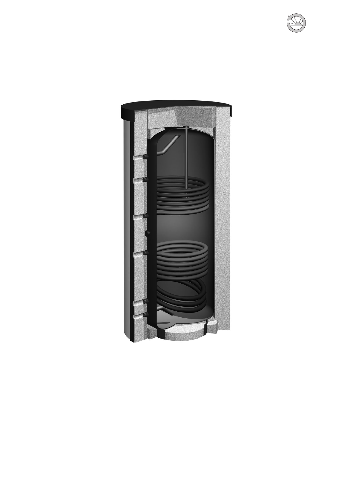
1.3 Intended Use and Application
ECOplus is an enameled solar storage tank for DHW heat-
ing in closed circuit heating and solar installations. It must
be filled with domestic water only. The maximum tem-
perature in the storage must not exceed 95 °C. Observe
correct settings at boiler and solar controllers (e.g. max.
boiler temperature)! The storage tank shall be placed in
a frost-proof room. The foundation at the installation site
has to be dry and sufficiently stable to support the filled
tank.
Wagner Solar cannot be held liable for damages resulting
from improper use.
2 Scope of supply
The ECOplus solar cylinder is supplied standing upright
and screwed onto a pallet.
The serial no. is located on the type label.
Table 1 Scope of supply (fig. 2)
1 Storage
2Jacket insulation with hook ratchet closure (may be several
parts, depending on storage type)
3 Insulation plug with cap for access flange
4, Insulation plug with cap for imersion heater socket
5 Storage lid
6 Lid insulation
7 Outer ground insulation
8 Inner ground insulation
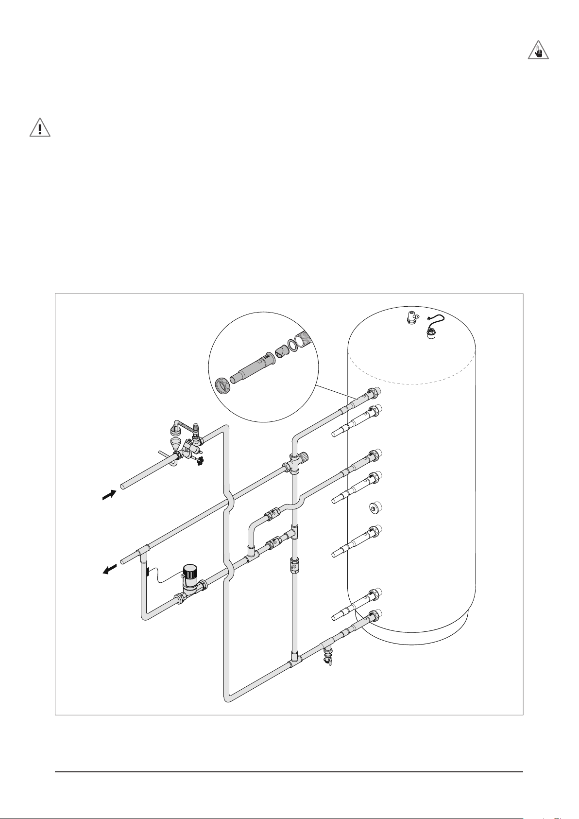
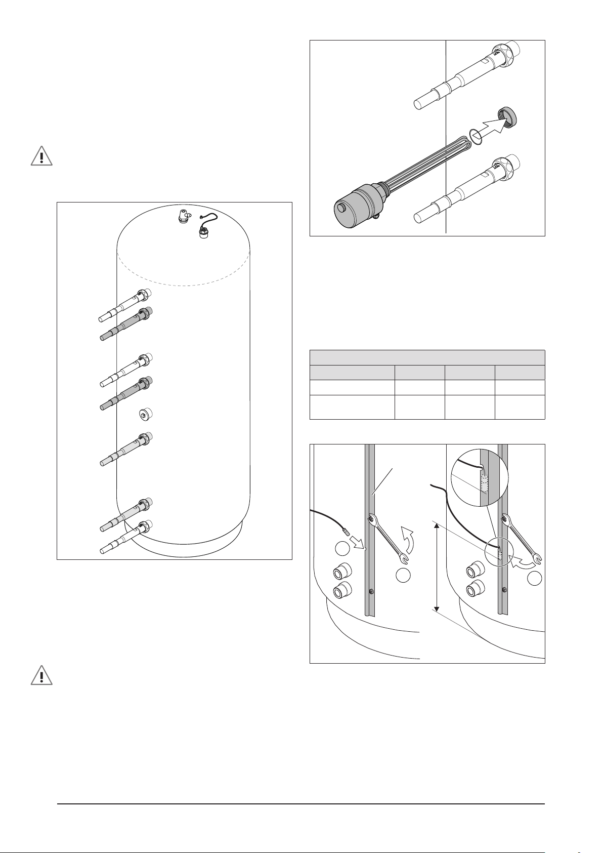
3 Installation
3.1 Preparation
The cylinder must be connected with short pipe lengths
to the taps.
In order to complete the installation the following materi-
als are required:
●Pipe connections to fit 1¼ “, 1“ and ¾“ male cylinder
connections.
●Thermostatic mixer (optional).
●Safety valve unit for the cold-water feed (optional).
All storage connection stubs are cylindrical and designed
for use with special heat resistant flat gaskets. The original
gaskets from our connection sets should be used or alter-
natively gaskets of identical quality.
To reduce heat losses we recommend to use the
CONVECTROL connection sets for all storage connection
stubs.
3.2 Setting up the Storage
Risk of injury during transport through heavy weight!
Wear safety shoes and protective gloves.
Knocks and banging can cause damage to the enamel
coating on the inside!
●Unscrew the storage from the palette, remove pack-
ing film and transport to the installation location.
The tank can be lifted at the foot ring and the hoisting
ring at the top.
●Positioning the storage tank for easy piping.
●Tilt the tank to place the round inner floor insulation
(fig. 3).