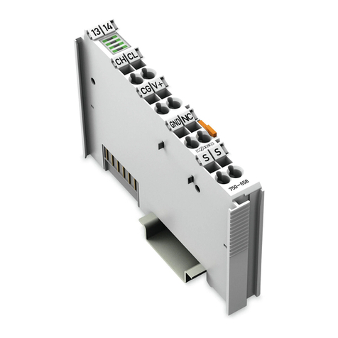
WAGO 750-658 Installation and operating instructions

Wago CAN gateway module
750-658
Application note
A500680, English
Version 1.0.1

ii • General
Application note
A500680e
Copyright 2009 by WAGO Kontakttechnik GmbH & Co. KG
All rights reserved.
WAGO Kontakttechnik GmbH & Co. KG
Hansastraße 27
D-32423 Minden
Phone: +49 (0) 571/8 87 – 0
Fax: +49 (0) 571/8 87 – 1 69
Web: http://www.wago.com
Technical Support
Phone: +49 (0) 571/8 87 – 5 55
Fax: +49 (0) 571/8 87 – 4 30
Every conceivable measure has been taken to ensure the correctness and com-
pleteness of this documentation. However, as errors can never be fully exclud-
ed we would appreciate any information or ideas at any time.
We wish to point out that the software and hardware terms as well as the
trademarks of companies used and/or mentioned in the present manual are
generally trademark or patent protected.

Table of Contents • iii
Application note
A500680e
TABLE OF CONTENTS
1
Important comments..................................................................................7
1.1
Legal principles.................................................................................7
1.2
Range of validity...............................................................................8
2
Description..................................................................................................9
3
Reference Material.....................................................................................9
3.1
Hardware...........................................................................................9
3.2
Software............................................................................................9
4
Modes........................................................................................................10
4.1
Mapped mode .................................................................................10
4.2
Transparent mode ...........................................................................12
4.3
Visualisation Templates..................................................................13
5
Example “Mapped mode”.......................................................................14
5.1
Configuration of module size .........................................................14
5.2
Configuration of filter and mapping data by CoDeSys...................14
6
Example “Transparent mode”................................................................16
6.1
Configuration of module size .........................................................16
6.2
Configuration by CoDeSys.............................................................16

Important comments • 7
Application note
A500680e
1 Important comments
To ensure fast installation and start-up of the units described in this manual,
we strongly recommend that the following information and explanation is
carefully read and adhered to.
1.1 Legal principles
1.1.1 Copyright
This manual is copyrighted, together with all figures and illustrations con-
tained therein. Any use of this manual which infringes the copyright provisions
stipulated herein, is not permitted. Reproduction, translation and electronic
and photo-technical archiving and amendments require the written consent of
WAGO Kontakttechnik GmbH & Co. KG. Non-observance will entail the
right of claims for damages.
1.1.2 Personnel qualification
The use of the product detailed in this manual is exclusively geared to special-
ists having qualifications in PLC programming, electrical specialists or per-
sons instructed by electrical specialists who are also familiar with the valid
standards. WAGO Kontakttechnik GmbH & Co. KG declines all liability re-
sulting from improper action and damage to WAGO products and third party
products due to non-observance of the information contained in this manual.
1.1.3 Intended use
For each individual application, the components supplied are to work with a
dedicated hardware and software configuration. Modifications are only admit-
ted within the framework of the possibilities documented in the manuals. All
other changes to the hardware and/or software and the non-conforming use of
the components entail the exclusion of liability on part of WAGO Kon-
takttechnik GmbH & Co. KG.
Please direct any requirements pertaining to a modified and/or new hardware
or software configuration directly to WAGO Kontakttechnik GmbH & Co.
KG.

8 • Important comments
Application note
A500680e
1.2 Range of validity
This application note is based on the stated hardware and software of the spe-
cific manufacturer as well as the correspondent documentation. This applica-
tion note is therefore only valid for the described installation.
New hardware and software versions may need to be handled differently.
Please note the detailed description in the specific manuals.

Description • 9
Application note
A500680e
2 Description
This application note presents how to use WAGO 750-658 module in the dif-
ferent modes.
3 Reference Material
3.1 Hardware
The following hardware components were used in this application note
Assigned hardware components Producer Type
Controller WAGO 750-880
CAN open slave WAGO 750-337
CAN gateway module WAGO 750-658
3.2 Software
The following software components were used in this application note
Assigned software components Producer Type
WagoLib_CAN_Gateway_02_example_01.pro
WAGO Example project
WagoLib_CAN_Gateway_02_example_02.pro
WAGO Example project
WagoLib_CAN_Gateway_02.lib WAGO library

10 • Modes
Application note
A500680e
4 Modes
Depending on the amount of data to be received and transmitted the module may be used either in
mapped mode (small amount of data, less than app.40 byte) or transparent mode.
4.1 Mapped mode
In mapped mode the data will be directly available by the process image of the module. No need
for a function block to receive or transmit data once the module is configured appropriately. This
may be done by using Wago-IO-Check.
If the configuration should be done by the CoDeSys application the function blocks
CAN_FullConfig and CAN_Communication have to be used.
If the module size and acyclic channel size is configured correct, the acyclic channel will show
MBX_OK while the CAN channel will show MBXERR_DENIED (OK since the CAN channel is
not available in mapped mode).
An additional function block CAN_FullConfigCheck allows to check module settings by compar-
ing the module internal CRC against the calculated CRC from variable tConfigData. A configura-
tion download may be performed depending on the result of the CRC check.

Modes • 11
Application note
A500680e
Furthermore it is possible to use the acyclic channel to do some configuration on the CAN net-
work. By using function block CAN_CIA405_NMT a CANopen slave may be set to operational
mode while CAN_CIA_SDO_WRITE4 will allow writing to the object dictionary of the slave.

12 • Modes
Application note
A500680e
4.2 Transparent mode
In Transparent mode the data will be accessed by different function blocks. The module needs to
be configured appropriately. This may be done by using Wago-IO-Check.
If the configuration should be done by the CoDeSys application the function blocks
CAN_FullConfig and CAN_Communication have to be used.
If the module size and acyclic channel size is configured correct, both channels will show
MBX_OK.
The function block CAN_FullConfig allows configuring the module.
An additional function block CAN_FullConfigCheck allows to check module settings by compar-
ing the module internal CRC against the calculated CRC from variable tConfigData. A configura-
tion download may be performed depending on the result of the CRC check.
Different function blocks are provided by the WagoLib_CAN_Gateway_02.lib library. They are
mostly organized in the folders CAN_Layer2 and CAN_CIA405 to program the data exchange
either with CAN or even CANopen devices.

Modes • 13
Application note
A500680e
4.3 Visualisation Templates
The library provides a template to view the diagnosis information of the module.
The placeholder “MBXaux3” must be linked to the instance of the diagnosis function block
CAN_Diagnosis.

14 • Example “Mapped mode”
Application note
A500680e
5 Example “Mapped mode”
5.1 Configuration of module size
The example project includes in the first network a function block, which checks the
CAN_gateway module size by power up.
This block must be the first block in an application program. This block will reset the controller
in case that the module size needs to be adjusted. Therefore this block will only work, if the li-
brary WagoLibReset is supported by the target system.
5.2 Configuration of filter and mapping data by CoDeSys
It is assumed that the node ID of the CANopen slave is 4. The slave will transmit one PDO
(0x184) with two bytes data. This data is received in inData[8] and inData[9] .
The slave will receive one PDO (0x204) with one byte data. Byte counting within PDOs starts
with 0 (D0, D1..D7). The transmitted data must be placed in OutData[8] .
Before the data exchange will start, the configuration of the gateway module is checked. If the
module settings do not match with the settings in the application program, the module will be
reconfigured. This technic allows replacing a faulty module without additional tooling.
The configuration will be explained in detail, though it is recommended to do the first configura-
tion with Wago-IO-Check and take over manually the configuration to the CoDeSys structure
CAN_typFullConfiguration.
The configuration is subdivided in four sections. The register area is set in Register 32 according
to 16#8230. This is 11bit mode, 125kBaude, mapped mode with active SDO communication us-
ing the acyclic channel.
The setting of these registers should not be changed unless a different configuration is used.
Please check the manual for detailed explanation of the bits within the registers.

Example “Mapped mode” • 15
Application note
A500680e
The filter setting should be set to allow receiving the appropriate CAN telegrams. In this example
all telegrams from 0x184 up to 0x186 will be received. The first filter is enabled due
to”Feature1”=1. “Feature2” =1 activates the override mode for these CAN telegrams.
myTx_Mapping is configured to transmit byte OutData[8] within PDO 0x204 by change of value
(SendGroup:=16#0410->04 change of value, 1-> 1 Byte in PDO).
FixedValue=1 ->enable transmission of byte D0
Data_0_1=16#0008 ->take data from position 8 (OutData[8] put in PDO 0x204 at position D0)
myRx_Mapping is configured to receive two bytes from PDO 0x0184 inInData[8] and InData[9].
CopyToPDIn:=16#0000_0011 ->bitmask for byte D0 and D1 from PDO 0x184
Data_0_1:=16#0908 -> copy D0 to inData[8] and copy D1 to inData[9]

16 • Example “Transparent mode”
Application note
A500680e
6 Example “Transparent mode”
6.1 Configuration of module size
The example project includes in the first network a function block, which checks the
CAN_gateway module size by power up.
This block must be the first block in an application program. This block will reset the controller
in case that the module size needs to be adjusted. Therefore this block will only work, if the li-
brary WagoLibReset is supported by the target system.
6.2 Configuration by CoDeSys
It is assumed that the node ID of the CANopen Slave is 4. The slave will transmit one PDO
(0x184) with two bytes data. The slave will receive one PDO (0x204) with one byte data.
Before the data exchange will start, the configuration of the gateway module is checked. If the
module settings do not match with the settings in the application program, the module will be
reconfigured. This technic allows replacing a faulty module without additional tooling.
The configuration will be explained in detail, though it is recommended to do the first configura-
tion with Wago-IO-Check and take over manually the configuration to the CoDeSys structure
CAN_typFullConfiguration.
The configuration is subdivided in four sections. The register area is set in Register 32 according
to 16#0130. This is 11bit mode, 125kBaude and transparent mode.
The setting of these registers should not be changed unless a different configuration is used.
Please check the manual for detailed explanation of the bits within the registers.
The filter setting should be set to allow receiving the appropriate CAN telegrams. In this example
all telegrams from 0x184 up to 0x186 will be received. The first filter is enabled due
to”Feature1”=1. “Feature2” =1 activates the override mode for these CAN telegrams.

Example “Transparent mode” • 17
Application note
A500680e
The components myTx_Mapping and myRx_Mapping are not needed in transparent mode and
are therefore disabled.
Receiving data is done by the function block CAN_L2_RX_11Bit_Frame while transmitting is
done by CAN_L2_TX_11Bit_Frame. For each PDO an instance of one of these function blocks is
needed.
The program action “SetModuleConfiguration” is a small state machine handling the function
blocks CAN_FullConfig and CAN_FullConfigCheck. Additional the CANopen slave will be
configured by CAN_CIA405_WRITE4.


WAGO Kontakttechnik GmbH & Co. KG
Postfach 2880 • D-32385 Minden
Hansastraße 27 • D-32423 Minden
Telefon: 05 71/8 87 – 0
Telefax: 05 71/8 87 – 1 69
Internet: http://www.wago.com
Other manuals for 750-658
1
Table of contents
Other WAGO Gateway manuals