WAGO-I/O-SYSTEM 750 Device Description 13
750-481/003-000 2AI RTD Ex i
Manual
V 1.4.0 HW-Version 07, SW-Version 41
Pos: 17 /Al l e Seri en (All g emei n e M o d ule) /Ü b er schr i f te n/ Eb ene 1/G er ät e bes chr eib ung - Ü ber sc hri f t 1 @ 3\mod_1233756084656_21.docx@ 27096 @ 1@ 1
3 Device Description
Pos: 18 .1.1 /S erie 750 ( WAGO -I/O-SYSTEM)/Gerätebeschreibung/Einleitung/Anwendung/AI/Anwendung750-0481AIExi Zone0 + 1 RTD/NTC @ 20\mod_1405937019517_21.docx@ 159528@ @ 1
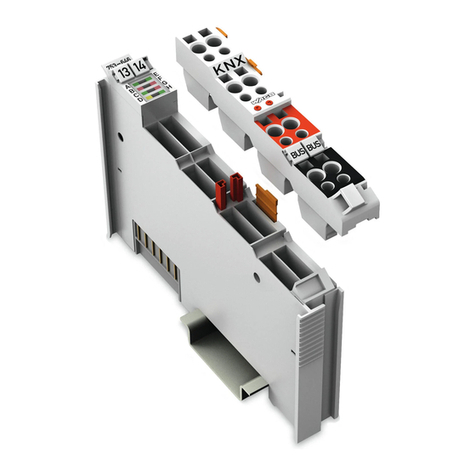
The Analog Input Module 750-481/003-000 (2AI RTD Ex i) processes signals
from resistance sensors that are operating in hazardous environments of Zones 0
and 1. Resistance thermometers (RTD), as well as resistors and potentiometers can be
connected.
Depending on the operating mode, the resistance value is converted to a
temperature or directly sent out by the module. A microprocessor within the
module is used for converting and linearizing the measured resistance value into a
numeric value proportional to the temperature of the selected resistance sensor.
Pos: 18 .1.2 /S erie 750 ( WAGO -I/O-SYSTEM)/Gerätebeschreibung/Einleitung/Anwendung/AI/Anwendung75x-04xxParametrierenmitWago IOCheck undGSD @ 28\mod_1487335005335_21.docx@ 408258@ @ 1
The WAGO-I/O-CHECK commissioning tool can be used to configure the
required operating mode. The I/O module can also be parameterized via
PROFIBUS and PROFINET device description (GSD file).
The parameterization description can be found in the appendix in Section
“Configuration and Parameterization via GSD File with PROFIBUS DP and
PROFINET IO.”
Pos: 18 .1.3 /S erie 750 ( WAGO -I/O-SYSTEM)/Gerätebeschreibung/Einleitung/Anwendung/AI/Anwendung750-046x V orei nst el l ung Pt1 0 0 @ 10\mod_1300281453847_21.docx@ 70923 @ @ 1
The default setting is Pt100.
Pos: 18 .1.4 /S erie 750 ( WAGO -I/O-SYSTEM)/Wichtige Erläuterungen/Sicherheits- und s ons ti ge Hin w eis e/ War nu ng / War n ung : E x i I nst al lat i o n des W AG O-I/ O-SYST EM 750 n ur in Zon e 2 oder i mni cht-ex-Berei ch @ 5\mod_1245851655116_21.docx@ 35947@ @ 1
Installation only in zone 2 or in non-hazardous environments!
The installation of the WAGO-I/O-SYSTEM 750 fieldbus couplers/controllers
and I/O modules is only to be done in zone 2 or in non-hazardous environments.
Pos: 18 .1.5 /S erie 750 ( W AG O-I/ O-SYSTEM)/Gerätebeschreibung/Einleitung/Anwendung/AI/Anwendung750-04xxAIExi (ohne 750-485) - nur M es s umf or mer oh ne eig ene Spg ver s. ansc hl ies se n @ 5\mod_1245849943157_21.docx@ 35934@ @ 1
To fulfill Ex i regulations, only passive transducers, that means without their own
voltage supply, like adjustable resistances, pressure, flow and level meters, may
be connected to the input module.
Pos: 18 .1.6 /S erie 750 ( WAGO -I/O-SYSTEM)/Gerätebeschreibung/Einleitung/Anwendung/AI/Anwendung750-04xxMessumformer v ersor gu ng di r ekt aus der B us kle mme @ 5\mod_1246287878058_21.docx@ 36324 @ @ 1
The transducers are directly supplied from the I/O module.
Pos: 18 .1.7 /S erie 750 ( WAGO -I/O-SYST EM )/G erä te bes c hrei bu ng/Ei nl ei tu ng/I/ O-B es c hr ei bu ng /A I/I /O-Besc hr ei bung 7 50-04xx 2 A I RTD/NTC @ 7 \mod_1274420216920_21.docx@ 56930@ @ 1
The module has two input channels allowing the direct connection of two 2- or 3-
wire resistance sensors.
For example, two 3-wire sensors can be connected either to +R1, RL1 and −R1 or
to +R2, RL2 and −R2.
Pos: 18 .1.8 /S erie 750 ( WAGO -I/O-SYST EM )/G erä te bes c hrei bu ng/Ei nl ei tu ng/I/ O-B es c hr ei bu ng /Al lg e m ein / V er wei s auf Kapi tel "A ns c hl üss e" @ 8\mod_1276775378035_21.docx@ 57956@ @ 1
The assignment of the connections is described in the “Connectors” section.
Pos: 18 .1.9 /S erie 750 ( WAGO -I/O-SYST EM )/G erä te bes c hrei bu ng/Ei nl ei tu ng/I/ O-B es c hr ei bu ng /Al lg e m ein / V er wei s auf Kapi tel "G er ät e ansc hli eß en" > " A nsc hl us s b eis pi el (e) " @ 5\mod_1246015203281_21.docx@ 36298@ @ 1
Connection examples are shown in section “Connect Devices” > … >
“Connection Example(s)”.
Pos: 18.1 .1 0 / S eri e 750 ( W AG O-I/O-SY ST EM ) /G erät e be sc hr ei b ung/ E inl eit ung / I/O -Beschreibung/AI/I/O-Beschrei bu ng 750-0 4 xx AI Ge mei ns a mer Schi rm a nschl us s @ 7\ mod_1274786880908_21.docx@ 56960@ @ 1
Each input channel of a module has a shield (screen) connection (S).
Pos: 18.1 .1 1 / S eri e 750 ( W AG O-I/O-SY ST EM ) /G erät e be sc hr ei b ung/ E inl eit ung / I/O -Beschreibung/AI/I/O-Beschrei bu ng 750-0 4 xx AI Sc hir ma nsc hl us s Kont akt mit T rag sc hi ene @ 5\mod_1246367742653_21.docx@ 36360@ @ 1
The shield connection is fed directly to the carrier rail and contact is made
automatically by snapping the module onto the rail.
Pos: 18.1 .1 2 / S eri e 750 ( W AG O-I/O-SY ST EM ) /G erät e be sc hr ei b ung/ E inl eit ung / L ED -Anz eig e /L ED Zus ta nd B et ri eb Kan al @ 5 \mod_1245391732046_21.docx @ 35668@ @ 1
The operating status of the channels is indicated by a green status LED per
channel.
Pos: 18.1 .1 3 / S eri e 750 ( W AG O-I/O-SY ST EM ) /G erät e be sc hr ei b ung/ E inl eit ung / L ED -Anz eig e /L ED F e hler Kurz sc hl uss / Dr a ht bruc h/ B er ei chs ü ber -/ unt ers c hr ei tu ng @ 5\mod_1245391942765_21.docx@ 35672 @ @ 1
A red error LED per channel indicates a wire break, a short circuit or that the
signal is outside the measuring range.
Pos: 18.1 .1 4 / S eri e 750 ( W AG O-I/O-SY ST EM ) /G erät e be sc hr ei b ung/ E inl eit ung / L ED -Anz eig e /V er weis auf Kapi tel "A nz eig eel e me nt e" @ 5\mod_1246010525000_21.docx@36194 @ @ 1
The meaning of the LEDs is described in the “Display Elements” section.


