Walkera WKRC-H15 User manual

www.walkera.com
User Manual
All-in-one HD GCS Remote
C
F
G
D
E
WKRC-H15
<<< >>>
K
<<< >>>
J
Sep. 22th 2020
V1.1
WKRC-H15


2
目 录
3
3
3
5
7
7
8
8
13
14
20
21
10
11
12
1.0 Introduction
2.0 Product considerations
3.0 Description of Ground End Panel
4.0 Installation of modules on the ground, sky, and flight controllers
5.0 RX-H15 sky end module connection diagram
6.0 WKRC app application settings
7.0 Parameters
8.0 List of items
2.1 Installation notes
2.2 Attention
4.1 Install the antenna on the ground end of WKRC-H15 and adjust the antenna
4.2 WKRC-H15 ground end opening and closing
4.3 Charging the WKRC-H15 ground remote control
4.4 RX-H15 sky end parts name
4.5 RX-H15 sky end installation antenna
4.6 FCS-F8 flight control module function description

1.0 Introduction
2.0 Product considerations
2.1 Installation notes
2.2 Attention
WKRC-H15 All-in-one HD GCS Remote is an all-in-one high-definition image transmission device with a bright display.The maximum
communication distance is 6km, and it supports local HD video shooting and recording. WKRC-H15 includes the sky end and the
ground end, works in the 2.4GHz frequency band, and can transmit video images, flight control system signals and ground end control
signals through wireless communication. Please ensure that WKRC-H15 is used in compliance with local laws and regulations. Please
read this manual carefully before use.
When using WKRC-H15, if the operation is improper, the aircraft may cause a certain degree of injury and damage to the person and
property. Please pay attention to safety when using it.
(1) Be sure to use spare parts provided by Walker.
(2) Be sure to install the antenna before powering on to avoid circuit damage.
(3) Try to keep the antenna at the sky end free of entanglement and unobstructed objects. The end of the antenna is vertically downward
and free from bending, to avoid shortening the communication distance due to the blocking, or even unable to communicate.
(4) When installing the sky-end antenna, pay attention to the antenna separation as far as possible to achieve better diversity. At the
same time, try to stay away from the large metal structural parts. Choose a location that will not be blocked in flight for installation.
(5) During the installation, pay attention to keep an appropriate distance between the electronic devices, so as to reduce the
electromagnetic interference between the devices to a minimum.
(1) Before use, make sure that all connecting cables are firm and reliable, and the interface is correct, then turn on the power.
(2) Make sure that no foreign objects (such as liquid, sand, etc.) enter the components.
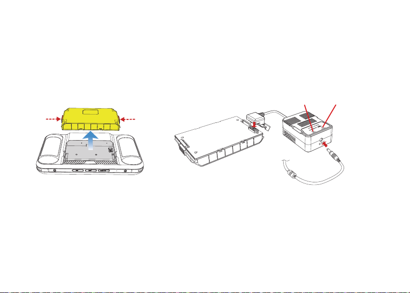
(3) Please check the power on the ground before use. If the power is insufficient, please charge in time.
(4) Please check the surrounding environment to ensure that there is no interference from other 2.4G devices. Otherwise, the video
transmission performance may be affected.
(5) Please pay attention to the angle and direction of the ground-side antenna during the flight. When the signal on the ground side is
poor or the image quality is not good, adjusting the tilt of the antenna on the ground side may have an improvement effect.
(6) For supporting electronic equipment, please select products with better electromagnetic shielding performance.
3

C
3.0 Description of Ground End Panel
4
WKRC-H15 All-in-one HD GCS Remote parts name
7
8
1. Antenna
2. F third gear switch
3. A button
4. Button B
5. C button
6. Power switch
7. E button
8. D button
9. G third gear switch
10. Right stick
11. Left stick
12. Charge completion indicator
13. Battery indicator
14. Charging indicator
15. Hook
16. Display
17. Micro SD card slot
18. High-definition output port (HDMI)
19. APP upgrade port
20. K dial
21. Charging port
22. Remote control upgrade port
23. J Dial
24. I button
25. H button
26. Battery
1
9
10
11
12 13 14 1515
16
17 18 19
2
6
3
4
5
Tips: A ~ K are all custom channels. The channel can be
customized through the flight control parameter.
C
F
G
D
E
WKRC-H15
26
Upgrade port Charge Port
15V 4A
H
I
<<< >>>
K
<<< >>>
J
24
20
25 2122
Upgrade port Charge Port
15V 4A
<<< >>>
K
<<< >>>
J
H
I
23

e
D
GCS Remote power switch description:
※ Warning: Forced shutdown may cause the remote controller data to be lost. Under normal
circumstances, it is forbidden to use the forced shutdown function. Only under special
circumstances can the forced shutdown function be used.
Turn on: Long press the power switch to turn on the remote control.
Shutdown / Restart: Long press the power switch, the GCS Remote
screen will pop up "shutdown" and "restart" operation interface.
Click "Shutdown" to turn off the GCS Remote;
Click "Restart" to restart the GCS Remote;
Screen off: Press the power switch once to turn off the screen;
Bright screen: Press the power switch once, the GCS Remote
screen will light up after 4 seconds;
Forced shutdown: Under special circumstances, press and hold the
power switch, and then press the D key after 8 seconds to force
shutdown.
Power
switch
5

6
Channel name
Channel
definition
(AILE) (Left: 1000 Right: 2000)
American hand: Pitch (ELEV) (up: 1000 down: 2000)
Japanese Hand: Throttle (THRO) (Up: 2000 Down: 1000)
American hand: Throttle (THRO) (up: 2000 down: 1000)
Japanese hand: Pitch (ELEV) (up: 1000 down: 2000)
Heading (RUDD) (Left: 1000 Right: 2000)
Up (1900) Middle (1500) Down (1100) Default: 1500
100 ~ 1900 (not pressing 1100, short pressing 1500 long pressing 1900)
1000 ~ 2000 Default: 1500
Right rocker
Right rocker
Left rocker
Left rocker
F three-speed switch
G three-speed switch
A button
B button
C button
D button
E button
H button
J button
K button
Output signal

7
4.0 Installation of modules on the ground, sky, and flight controllers
4.1 Install and adjust the antenna on the GCS Remote end of WKRC-H15
Install the antenna and adjust the position of the antenna on the ground.
The signal strength received at different antenna positions is different.
Note: When maneuvering the aircraft, make sure that the aircraft is in the best communication range. Adjust the azimuth or distance
between the operator and the aircraft in time to ensure that the aircraft is always within the optimal communication range.
Best communication range
Do not use other communication
devices in the same frequency
band at the same time to avoid
interference with the GCS Remote
signal.
Weak
Strong
WKRC-H15
C
e
D
Upgrade port Charge Port
15V 4A
<<< >>>
K
<<< >>>
J
H
I

C
e
D
F
G
8
4.2 WKRC-H15 GCS Remote end on and off
There is a built-in 2S rechargeable battery with a capacity
of 9000mAh on the ground. You can check the current
power through the battery power indicator.
Install the battery on the remote control. Press and hold
the power switch on the ground side for 2 ~ 3 seconds
to turn on the ground side, and the green indicator
light on the ground side will be steady on. Press and
hold the power switch on the ground side for 2 ~ 3
seconds to turn off the ground side.
4.3 WKRC-H15 GCS Remote Charging
Tip: This device has a built-in lithium battery 7.4V 9000mAh,
which can be charged with DC15V 4A.
Method one:
1) Plug the power adapter into an AC
power source (100 ~ 240V 50 / 60HZ).
2) Please charge when the GCS Remote is off.
3) The charging indicator of the GCS Remote
is steady green-full.
Power adapter
AC Power
100 ~ 240V
Figure 4.2-1
Figure 4.3
Low High
Power
高
Figure 4.2-2
Upgrade port Charge Port
15V 4A
H
I
<<< >>>
K
<<< >>>
J

9
Method Two:
Charge with GA008 charger.
1) To charge with the GA008 charger, the battery must be removed from the remote control, as shown in Figure 4.3-1.
2) Connect the remote controller battery, GA008 charger, 15V 4A power adapter to charge as shown in Figure 4.3-2.
3) The GA008 charger indicates that the red light is always on --- means charging, and the green light is on --- means it is fully
charged.
Figure 4.3-2
Green indicator Red indicator
Figure 4.3-1
Press the buttons on both sides and
remove the battery upward

10
4.4 RX-H15 sky end parts name
1. S1 button: Reset button.
2. S2 button: Frequency-matching button, through which the
frequency can be carried out between the sky and the ground.
3. Indicator.
4. Antenna port: Connect the sky antenna.
5. SBUS port: Built-in receiver port, connected to the SBUS port
of the flight controller.
6. UART port: 3.3V / 5V level UART port.
Precautions:
When using the video input port, the HDMI port can be used simultaneously with the OTG port or USB
port, while the OTG port cannot be used simultaneously with the USB port.
7. DC 5V port: Is used to power the sky side.
8. HDMI port: Is used for the input of external camera video signals.
9. OTG port: Is used for the input of external camera video signals.
10. USB port: Used for external camera video signal input or connected
to PC for parameter adjustment.
11. Cooling fan To ensure normal heat dissipation, do not block the heat
dissipation holes.
SBUS UART DC 5V
++
--
78
126
3
10
11
9
5
4
4

11
Precautions
1) Be sure to install the antenna before powering on to avoid damage to the circuit.
2) When using, try to keep the antenna facing down and obstructed by obstacles, to avoid the communication
distance being shortened due to blocking, or even unable to communicate.
3) Be sure to install and use the original antenna correctly. It is forbidden to use other antennas.
4) If the aircraft used is large, it is recommended to use the sky antenna extension cable to connect the sky
terminal and the sky antenna.
4.5 RX-H15 sky end installation antenna
The sky side needs to communicate with the ground side through the antenna.
Please install the antenna as follows:
1. Install the sky antenna extension cable to the sky antenna port as shown below.
2. Use foam double-sided tape or other methods to fix the sky end to the reserved position of the flight platform or other suitable
flat surface, tighten the antenna to the antenna extension cable.

12
4.6 FCS-F8 flight control module function description
1. DC Power supply 3~12S
2. Serial port 7
3. Serial port 6
4. SWD
5. USB
6. Serial port 1
7. Serial port 3
8. Serial port 4
9. Serial port 8
10. LED2
11. IMU
12. LED1
13. GPS Signal indicator
USB UART1SWD
POWERUART6 UART7
+
+
GPSIMU
UART3
LED2
LED1
UART8 UART4
+
+
-
-
1 892
3 10 7
4 5 6 11 12 13
M1
M2
M3
M4
M5
M6
M7
M8
M9
M10
M11
M12
Servo 1
Servo 2
Servo 3
Servo 4
Servo 5
Servo 6
Servo 7
Servo 8
Servo 9
Servo 10
Buzzer
SBUS
Battery voltage test
AD
RC
BUZZ
S10
S9
S8
S7
S6
S5
S4
S3
S2
S1
FCS-F8
Made in China
M1
M2
M3
M4
M5
M6
M7
M8
M9
M10
M11
M12
(Motor)

13
5.0 RX-H15 sky end module connection diagram
GPS antenna bracket connected
Connect to
POWER IN
Connect to UART6
Serial port
Connect to
Power
GPS portLED2 port
SBUS UART DC 5V
++
--
AD
RC
BUZZ
S10
S9
S8
S7
S6
S5
S4
S3
S2
S1
FCS-F8
Made in China
M1
M2
M3
M4
M5
M6
M7
M8
M9
M10
M11
M12
FCS-F8 Power Box
Made in China
32
1
3
2
1
Connect to
POWER OUT
GPS signal
indicator port
GPS Signal indicator
+
-
GPSIMU
UART3
LED2
LED1
UART8 UART4
+
+
-
-
USB UART1SWD
POWERUART6 UART7
+
+
Serial port
control cable

14
6.0 WKRC app application settings
6.1 Turn on the power switch of the remote control.
6.2 Open the WKRC app in the main screen interface and enter the
setting interface (see Figure 6.2).
Figure 6.3-1
Figure 6.2
Figure 6.3-2
Note: If the WKRC app application software is updated,
the remote controller will prompt itself to update the
latest version after connecting to the Internet.
6.3 Remote Setting:
(1) Touch "Remoter Setting" to enter the remote control joystick
mode selection interface, you can choose Japanese or American
hands (see Figure 6.3-1 / Figure 6.3-2).

15
(2) Touch "RC Channel" to enter the remote control channel setting interface, please make settings according to your actual needs.
Figure 6.3-3 Figure 6.3-4

6.4. Transmission Setting:
Touch "Transmission setting" to enter the image transmission setting interface, you can choose to image transmission frequency or
restart the image transmission.
Frequency-matching method:
First press the S2 frequency-matching button on the RX-H15 sky end to put the sky end in the frequency-
matching state, and then select the image transmission frequency-matching.
Figure 6.4-1 Figure 6.4-2
16

6.5 UAV Parameter setting:
After the flight control is connected, touch "UAV Parameter" to enter the flight control parameter setting interface.
Please set it according to your actual needs.
Figure 6.5-1 Figure 6.5-2
17

6.6 Frame Selection
After the aircraft is connected, touch "Frame Selection" to enter the rack selection interface. Please select it in conjunction with the
aircraft.
Figure 6.6-1 Figure 6.6-2
18

6.7 Sensor Calibration
After the aircraft is connected, touch “Sensor Calibration” to enter the calibration interface. Please perform calibration with the aircraft.
Figure 6.7-1 Figure 6.7-2
19
Table of contents
Other Walkera Transmitter manuals
Popular Transmitter manuals by other brands

technetix
technetix AIMA3000.FT5S Product user manual

MICROTRONIX
MICROTRONIX J1 user manual

Zhongshan K-mate General Electronics
Zhongshan K-mate General Electronics AT1900 user manual

Emerson
Emerson Rosemount 1408H Reference manual

Clas Ohlson
Clas Ohlson LHF-800 user manual

Powercast
Powercast Powercaster TX91503 user manual