Setup wizard
1-.Connect the power supply. The display will show the message Inl flashing with 0.
2-.Use keys N and Q to select one of the options depending on the type of installation and press SET
to confirm:
InI=0: Demo mode*
InI=1: Connection to alarm station
InI=2: Independent operation
If 1 minute elapses without any key being pressed, the transmitter will automatically proceed
to demo mode*.
AKO-575400N and AKO-575400NE only
3-.The display will show the message Gc2. Use keys N and Q to select the type of gas to be measured (ALL, 125, 134A, 404A, 407A, 407F, 410A, 448A,
449A, 513A, 452A, 32, 23 or 455A), and press SET to confirm.
All models
The transmitter will begin to operate normally.
If the transmitter is connected to an alarm station, initiate the configuration wizard in the transmitter before doing so in
the station.
This function will not reactivate once the transmitter has been configured. To reactivate the function, disconnect the power supply, reconnect it
and press N, Q and SET before 2 minutes are up.
4-.If this is not the first time you initiate the wizard, after completing the last step the display will show the message dFp (parameters per defect). You
may choose between two options:
0: Only changing the parameters which affect the wizard (Gc2, b04 and o00). The other parameters will remain the same.
1: All parameters return to their factory setting except those which have been modified by the wizard,
It is advisable to reset to zero on start-up. For further information, refer to the user manual available on www.ako.com
* Demo mode shows the reading of the gas concentration on a flashing panel with the message Inl. It does not activate Alarms or Pre-Alarms. This mode
enables you to postpone configuration of the transmitter.
Signing up to akonet.cloud
In order for the transmitter to be able to send operating data to akonet.cloud, it must be registered. To
do this, go to (requires registration), click on “Add new device” and continue https://akonet.cloud MAS
with one of these two methods:
A.-Enter the serial number (S/N) and validation code / IMEI that appear on the tag and press
“Search”.
B.-Capture the QR code that appears on the tag using the option (requires having a camera QRC
on your PC, tablet or mobile phone).
These data are found on the tag on the right hand side of the transmitter.
More information can be found in the akonet.cloud user guide at:
”http://help.ako.com/manuales/akonet-cloud”
To access akonet.cloud, enter this address in your browser (the use of Google Chrome is
recommended): https://akonet.cloud.
Before activating the device, make sure that there is enough reception at the
installation location. Activated devices may not be returned.
Forcing transmission
When the steps of the configuration wizard and the registration process are completed in
akonet.cloud, you must force a first transmission to verify the level of reception:
ŸPress and hold the ESC and SET keys for 3 seconds.
ŸAfter a moment, the display shows the quality of the NBIoT signal received:
The transmitter does not start transmitting data to akonet.cloud until the first transmission is forced.
2
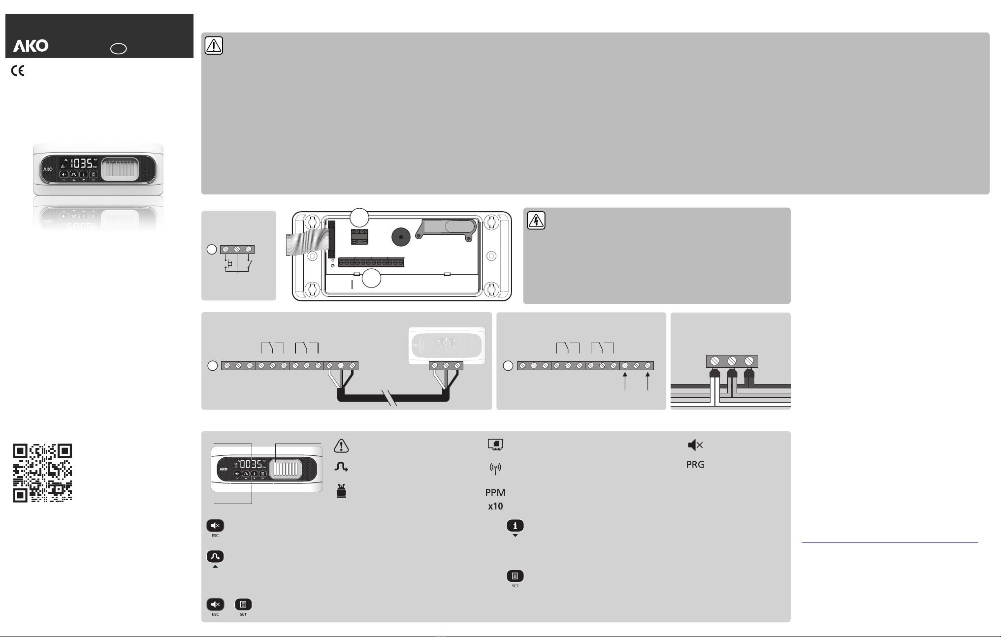
Parameters
The unit operating parameters are organised in different groups or families according to their function. The Def. column indicates the default parameters set in the factory. In order to
access the programming menu, hold the SET key for 6 seconds, or until ''PRG'' appears on the display. To modify the Pre-Alarm and Alarm levels, press SET for 3 seconds or until “Al3”
appears on the display (Only if AL1=1).
Technical specifications
Power supply..................................................................................................12 - 30 Vdc
Consumption Typical .............................................................................................75 mA
Maximum ......................................................................................125 mA
Pre-Alarm/Alarm relay ............................................................SPDT 30 Vdc, 2 A, cos j =1
Working ambient temperature...................................................................-30 ºC to 50 ºC
Storage ambient temperature ....................................................................-30 ºC to 60 ºC
Range of maximum moisture permitted 0 95 without condensation...................... - % HR ( )
Protection degree AKO-575400NE..........................................................................IP65
Other models.............................................................................IP68
Type of sensor.................................................NDIR (Non-Dispersive Infrared Technology)
Display range ........................................................................................0 - 2000 x1 ppm
Estimated working life..........................................................................................7 years
Dimensions..............................................................202 mm (W) x 82 (H) x 55.5 mm (D)
Bands.........................NBIoT (Narrow band) LTE Cat NB1 | B2, B3, B4, B8, B12, B13, B20
Band Frequency Rx Frequency Tx
2 . . . . . . . . . . . . . . 1930 MHz ~ 1990 MHz . . . . . . . . . . 1850 MHz ~ 1910 MHz
3 . . . . . . . . . . . . . . 1805 MHz ~ 1880 MHz . . . . . . . . . . 1710 MHz ~ 1785 MHz
4 . . . . . . . . . . . . . . 2110 MHz ~ 2155 MHz . . . . . . . . . . 1710 MHz ~ 1755 MHz
8 . . . . . . . . . . . . . . . 925 MHz ~ 960 MHz . . . . . . . . . . . . 880 MHz ~ 915 MHz
12. . . . . . . . . . . . . . . 729 MHz ~ 746 MHz . . . . . . . . . . . . 699 MHz ~ 716 MHz
13. . . . . . . . . . . . . . . 746 MHz ~ 756 MHz . . . . . . . . . . . . 777 MHz ~ 787 MHz
20. . . . . . . . . . . . . . . 791 MHz ~ 821 MHz . . . . . . . . . . . . 832 MHz ~ 862 MHz
Maximum transmission power .........................................................23.5 dBm conducted
Antenna AKO-575400NE .................................................................................External
Other models.....................................................................................Internal
1
Low quality Intermediate quality High quality Communication error
A
B
S/N:
Valid. code / IMEI:
This allows you to scroll through the different levels, or
when setting a parameter, to change its value.
This accesses the level shown on the display or, when
setting a parameter, it accepts the new value.
This exits the parameter without saving changes, returns
to previous level, or exits programming.
Alarm levels: 0: According to regulation
1: Set by user
Pre-Alarm 0: Disabled; 1: Enabled
Pre-Alarm Delay (0: Disabled)
Alarm Delay (0: Disabled)
Type of gas to be measured (Reading only)
Gas to be measured with the Universal sensor (Only if Gc1=brd1)
ALL; 125; 134A; 404A; 407A; 407F; 410A; 448A; 449A;
513A; 452A; 32; 23; 455A (2)
Display 0: Measurement in PPM 1: Type of gas to be measured
Minimum value to be shown on the display (Lower values are
shown as 0) Does not affect the values shown by
communication (AKONet or CAMM module)
Function of the mute key (Applicable to Alarm and Pre-Alarm)
0: Disabled 1: Deactivate acoustic alarm
2: Deactivate relay 3: Deactivate both
Acoustic alarm 0: Disabled 1: Enabled
Access code (password) function 0: Disabled;
1: Block access to parameters 2: Block keypad
MODBUS speed 0: 9600 bps 1: 19200 bps
2: 38400 bps 3: 57600 bps
Level 1
Level 2
INPUT AND OUTPUT CONFIGURATION
Reset to zero of the sensor (Calibration only)
0: Disabled 1: Reset to zero activated
Setting the sensor (Calibration only)
0: Disabled 1: Setting activated
Polarity of digital input 1 (Remote Mute)
0: Activates on opening contact; 1: Activates on closing contact
Polarity of digital input 2 (Remote Set Hold)
0: Activates on opening contact; 1: Activates on closing contact
Type of output 4/20 mA (Reading only)
0: Calibrated for alarm station; 1: Linear
INFORMATION (Reading only)
Operation modes (Reading only) 0: Demo mode;
1: Connection to alarm station 2: Independent operation
CRC value of the programme
CRC value of the bootloader
Level 1
Level 2
(1) In order to modify these levels, parameter AL1 should be configured to 1.
(2) R-450A, R-442A, R-454A, R-454C, R-1234YF, R-1234ZE are detected using GC2=ALL.
(3) According to the setup wizard.
(4) The MODBUS address will be shown on the transmitter label by default.
Gas pre-alarm activated. Flashing together with the gas concentration.
Gas alarm activated. Flashing together with the gas concentration.
Initialisation process of the gas sensor. This may last for up to 3 minutes.
Error or malfunction of the sensor. The Pre-Alarm relay is activated, the transmitter emits 3
alert tones every 2 minutes and the icon flashes. Deactivate the power supply and ALM
activate it again. If after a few seconds the error persists, please contact your technical
support centre.
The sensor has reached its maximum working temperature.
The sensor has reached its minimum working temperature.