Safety Precautions
THIS MANUAL HAS BEEN PREPARED FOR PERSONNEL QUALIFIED TO INSTALL,
MAINTAIN AND REPAIR ELECTRICAL REFRIGERATION EQUIPMENT, WHO SHOULD
PERFORM THE INITIAL FIELD STARTUP AND ADJUSTMENTS OF THE EQUIPMENT
COVERED BY THIS MANUAL.
READ THIS MANUAL THOROUGHLY BEFORE OPERATING, INSTALLING, PERFORMING
MAINTENANCE ON, OR REPAIRING THE EQUIPMENT.
WARNING Failure to follow all the instructions in this manual can cause property
damage, injury or death.
WARNING Improper installation, adjustment, alteration, service or maintenance can
cause property damage, injury or death.
WARNING Electrical connections should be performed only by a certified professional.
Electrical and grounding connections must comply with the applicable portions of the
National Electric Code and/or all local electric codes. Failure to comply with this
procedure can cause property damage, injury or death.
WARNING Before connecting the unit to the electrical supply, verify that the electrical
and grounding connections comply with the applicable portions of the National Electric
Code and/or other local electrical codes. Failure to comply with this procedure can
cause property damage, injury or death.
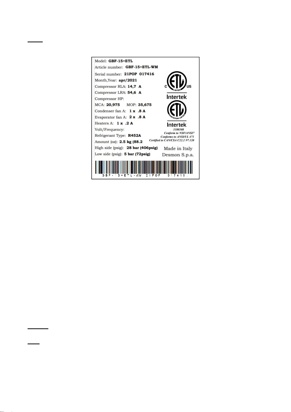
WARNING Before connecting the unit to the electrical supply, verify that the electrical
connection agrees with the specifications on the data plate. Failure to comply with this
procedure can cause property damage, injury or death.
WARNING Appliance must be connected to a grounded, metal, permanent wiring
system. Or an equipment-grounding conductor must be run with the circuit conductors
and connected to the equipment-grounding terminal or lead on the appliance. Failure to
comply with this procedure can cause property damage, injury or death.
WARNING Appliances equipped with a flexible electric supply cord, are provided with a
three-prong grounding plug. It is imperative that this plug be connected into a properly
grounded three-prong receptacle. Failure to comply with this procedure can cause
property damage, injury or death.
WARNING If the receptacle is not the proper grounding type, contact an electrician. Do
not remove the grounding prong from the plug. Failure to comply with this procedure
can cause property damage, injury or death.
WARNING Before performing any service that involves electrical connection or
disconnection and/or exposure to electrical components, always perform the Electrical
LOCKOUT/TAGOUT Procedure. Disconnect all circuits. Failure to comply with this
procedure can cause property damage, injury or death.