Regulus PG 600 S User manual

www.regulus.eu
PG 600 S
PG 600 S
EN
Installation and Operation Manual
PG 600 S BACKUP POWER SUPPLY

CONTENTS
SAFETY INFORMATION ..................................................................................................................... 3
TAKING CARE OF YOUR BATTERY ................................................................................................... 4
1 ESSENTIAL INFORMATION - USE, FEATURES, DESCRIPTION ........................................... 5
1.1 GENERAL DESCRIPTION ........................................................................................................ 5
1.2 FRONT PANEL ......................................................................................................................... 6
1.3 REAR PANEL ........................................................................................................................... 9
2 INSTALLATION ......................................................................................................................... 9
2.1 RECOMMENDED WIRING ....................................................................................................... 9
2.2 TURNING PG 600 S ON WITH NO GRID POWER ............................................................... 15
2.3 TURNING PG 600 S OFF ....................................................................................................... 15
3. OPERATION MODES ............................................................................................................. 15
4. SETTINGS .............................................................................................................................. 16
5. POSSIBLE FAULTS, TROUBLESHOOTING .......................................................................... 16
6. TECHNICAL DATA ................................................................................................................. 19
2

SAFETY INFORMATION
The appliance shall be installed by a trained person. The Manual is intended for an informed person.
The contents of this Manual may change over time.
THE APPLIANCE OPERATES WITH VOLTAGE DANGEROUS TO HUMAN LIFE. PLEASE STICK
TO SAFETY INSTRUCTIONS GIVEN IN THIS GUIDE, PREVENTING THUS RISK OF ELECTRIC
SHOCK.
IMPORTANT
Wrong wiring or handling may cause damage to the appliance itself or connected devices!
Prior to beginning with installation and start of the appliance, please read the Manual carefully and
follow the instructions meticulously! These electrical appliances shall be earthed in compliance with the
valid standards. The cross-sections of the power supply cables and their current ratings shall conform
to the nominal current values on the label and to the specification of the appliance as required by a
respective rule valid for low-voltage electric appliances. Prior to installation of this electric appliance
please make sure all safety (circuit breakers and fuses) and switch-off elements are off. Batteries may
only be handled by trained, informed and experienced persons sticking to all applicable safety measures.
Before touching the battery clamps, all safety and switch-off elements at the appliance itself, batteries,
as well as safety and switch-off elements at the electric device outlet shall be switched off!
Do not put any tools, instruments or other, esp. metal items on batteries!
Do not push any objects into the appliance through the ventilation or other openings!
Use a damp cloth to clean the casing. Take care not to let moisture or water into the appliance through
the ventilation or other openings!
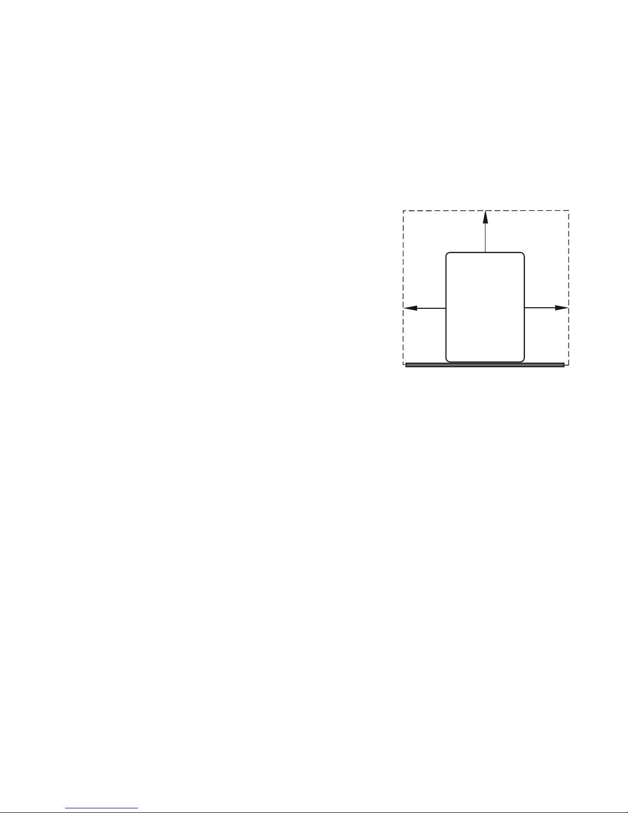
The appliance shall be installed in a sufficiently spacious and ventilated room enabling good access. It
shall never be exposed to weather!
Whenever handling a battery and PG 600 S, the PG 600 S shall be turned off and disconnected from
the power supply.
PG 600 S is not designed for use with an automotive battery.
The backup time depends on the power drawn by the device(s) connected to the PG 600 S. The higher
is the connected load, the shorter is the backup time.
PLEASE RESPECT THE FOLLOWING INSTRUCTIONS
The appliance may be installed by authorized staff only!
When switching off the electric appliance fed by PG 600 S do not forget to switch off the PG 600 S itself
as well. Otherwise the its inverter continues to supply electricity from its battery and does not switch off
until the battery voltage drops below the set min. value.
Even if the appliance is turned off, the battery voltage is still present at the clamps.
No terminal of the unit’s outlet socket shall get connected to any lead of mains or any other electric
wiring. The unit is designed for a closed circuit. If the unit’s outlet got connected with the mains, there
would be a danger of destroying the connected appliances, the unit itself, and even causing harm to
health and property. The only lead that may be connected outside TN-S network is the protective
yellow-green lead.
When testing the backup function, never unplug PG 600 S from el. socket. Doing so would interrupt the
PE line. De-energizing shall be done by a circuit breaker or a fuse.
PG 600 S shall always be used with the battery connected.
Do not leave the appliance turned off for more than 6 months unless its batteries had been fully charged.
The appliance should be completely cleaned by a serviceperson at least twice a year. Cooling is
hindered by dust inside and the appliance might suffer damage from overheating.
Check annually that the battery terminals are properly tightened.
3

TAKING CARE OF YOUR BATTERY
The appliance is equipped with maintenance-free lead acid batteries. The following rules shall be
respected when using them:
Avoid any mechanical stress, especially by a hit.
Avoid any damage to the battery casing and do not attempt to open it. The acid inside is toxic, dangerous
to skin and eyes! In no case shall the battery be exposed to high temperatures or flames. There is a
risk of explosion!
When the batteries are to be replaced and new ones installed, their number, model, wiring manner and
capacity set by the manufacturer shall be maintained. Only an authorized serviceperson may do that.
In a room where the battery is placed the temperature shall be kept at 20 °C ± 5 °C. At temperatures
above 20 °C the battery lifetime deteriorates, at temperatures below 20 °C the battery capacity
deteriorates.
SAFETY INSTRUCTIONS REGARDING THE BATTERY
Never wire and charge very cold batteries (exposed to freezing temperatures).
A battery represents a serious threat to human health and the environment. It shall be disposed of in
compliance with a valid legislation.
Be extremely careful when using metal items and tools near the battery.
When working with the appliance, refrain from smoking and using open flame! Do not use water to
extinguish eventual fire, danger of explosion!
Gases develop in all lead acid batteries during charging. In traditional unsealed batteries these gases
escape into the air. In batteries with pressure valves most of these gases recombine inside the battery
and just a very small portion escapes into the air.
Always ensure good ventilation for battery cabinets or rooms (at least 1 l of air per hour). Hydrogen gas
may explode and cause serious injuries and fire.
After a long period of operation, the capacity of lead acid batteries decreases. This is quite normal. For
their proper operation in your system you should test their backup function at least once a year in order
to find out whether the backup period is sufficient.
Should the battery become very hot, make sounds or inflate, leave the room immediately!
ACID BURN INJURY
Should the acid get in contact with skin, take off
immediately all contaminated clothing, and wash
immediately with plenty of water, use sterile gauze
bandage and special medical aids.
In case of contact of acid with eyes, rinse immediately
with plenty of water and call emergency and
ambulance. In all emergency, life-threatening
situations contact a doctor asap.
HOW TO ENSURE LONG LIFE FOR YOUR BATTERY
Never store a discharged battery. Storing a discharged battery will cause its definitive destruction.
Always charge it prior to storing and disconnect all leads from the battery poles. The battery may be
stored for a longer time in this manner only. At the same time, it is recommended to charge it every 3
months. Older batteries shall be checked more frequently.
Should the UPS be disconnected from the mains for a longer time, it is unconditionally necessary to
disconnect also the battery from the UPS.
4

1 ESSENTIAL INFORMATION - USE, FEATURES, DESCRIPTION
- PG 600 line UPS is intended preferably for circulation pumps in heating systems.
- The PG 600 S load shall not exceed the value shown on the label placed on its rear panel.
- Use rechargeable lead acid batteries only, supplied by Regulus, designed for backup power supplies.
- The appliance is designed for indoor use. Do not expose it to adverse weather (direct sunshine, rain)
nor to increased humidity. Protect from dust.
- The ON/OFF button does not disconnect electrically the internal circuitry. In order to de-energize the
PG 600 S, it is necessary to disconnect the power supply by pulling out the power cord and
disconnecting the battery.
- Do not put anything on PG 600 S.
- Do not expose PG 600 S to high temperatures.
- Do not open the cover of PG 600 s when any of its internal circuits
are energized; this may apply even if the power supply at the input
terminal is disconnected. In no case any repair of internal parts of
PG 600 may be performed by a user.
- The front panel is designed for manual control; do not use sharp
or pointed items.
- PG 600 S is not designed for operation in explosive environment.
- Both PG 600 S and the battery shall be placed in a sufficiently
ventilated space. Ventilation openings shall not be covered and air
intake shall not be obstructed. The minimum distance of PG 600 S
is shown in the pic.
- When PG 600 S is in operation, its fan is running. Its switching is
controlled (by its inner temperature).
1.1 GENERAL DESCRIPTION
When the unit is power-supplied from the grid, the electricity runs via its internal bypass directly to its
outlet socket. At the same time, the battery is being charged. In case of a power failure, the inverter
turns on and the load is fed from the integrated batteries. During charging, the temperature of the unit
may rise to circa 45 °C (normal operation state).
FEATURES
• Automatic switching from line to battery and vice versa
• High efficiency inverter
• Smart 3-stage charger control with overcharge protection
• Battery overload and deep discharge protection
• Backlit LCD display and sound signals
• Inner temperature controlled fan
• Smooth output sine-wave
• Adjustable charging current
• Protection against battery terminal reversal
5
100 mm
100 mm 100 mm
UPS

1.2 FRONT PANEL
1. ON push button 10. select
2. OFF push button 11. confirm
3. display
4. by-pass indicator
5. input AC voltage indicator
6. battery indicator
7. output AC voltage indicator
8. error indicator
9. back
Visual indicators and sound alarms
The front panel is fitted with 5 LED indicators.
All LED indicators are off.
6
Indicator Meaning
Battery operation
Power grid operation
Charging mode
Discharged battery warning The audio alarm sounds every 2 s and the red LED flashes. At
the same time, the symbol .
Overload warning The audio alarm sounds every 2 s and the red LED flashes. At
the same time, the symbol .
Adjustment warning The audio alarm sounds every 2 s and the red LED flashes. At
the same time, the symbol .
Fault Zvukový alarm zní nepřetržitě a červená kontrolka svítí.
The front panel of the horizontal model is fitted with 3 LED indicators.
The LED is lit all the time when the grid power supply is on,
except for the charging mode.
The battery LED is permanently on, except for the charging
mode.
Whenever a warning is issued, the fault LED will start flashing. In
the fault mode the LED is lit continuously.

Display info
The information to be shown can be retrieved by repeated pressing the Select key. The displayed
information is presented in the table below.
Optional info Display
Imput Input voltage = 230 V, input frequency = 50 Hz
Battery Battery voltage = 24,8 V, battery current = 1 A
Output Output voltage = 230 V, output frequency = 50 Hz
Load Power output = 879 W, percentage = 88 %
Load Power output = 312 W, apparent power output = 445 VA
Temperature Temperature = 30 °C
7

Display Function
Battery info in AC mode: Charging condition is shown.
Condition Battery voltage Display
Constant current
/ constant volt-
age mode:
0%-25% All bars gradually blink.
25%-50% The bottom bar is lit and the remaining three gradually blink.
25%-50%
The bottom two bars are lit and the remaining two gradually blink.
75%-100% The bottom three bars are lit and the top one blinks.
Float mode: Batteries are fully charged. All bars are lit.
Battery mode: Info will contain data on the battery capacity.
Battery voltage Display
0%-25%
25%-50%
25%-50%
75%-100%
Load info:
Flashing load symbol means overload.
Load level shown in stages: 0%-25%, 25%-50%, 50%-75% and 75%-100%
Operation mode
info: see Operation mode description
Audio alarm info: Short pressing the ON button will turn it on/off.
Muted
Normal
Optional info: see Display info
LCD Display
8

1.3 REAR PANEL
The rear panel is fitted with:
1. fax/phone IN, OUT
2. fan
3. PC terminal to connect PG 600 S to power grid (INPUT)
4. two 230V sockets (OUTPUT)
5. cables to connect battery ( + - )
6. removable fuse (F10A/230V)
1
2
3
4
6
2 INSTALLATION
1. Read the entire Installation and Operation Manual incl. Safety information and Taking care of your
battery.
2. Make sure the power grid voltage corresponds to the voltage PG 600 S is designed for.
3. Connect the battery using either M6 screws (for 44 and 100 Ah batteries) or M5 screws (for 18 Ah
battery). MIND THE POLARITY, + red / - blue or black. Max. torque is shown on the batteries (mostly
5-7 Nm). Fit the battery terminals with protective covers. Avoid terminal reversal!
4. Plug the power supply cord of PG 600 S into a wall socket. WARNING – PG 600 S is now switched
on and from the moment on the battery is being charged. At the same time, the internal cooling fan
also starts running.
5. Connect your pump or another load by plugging its cable into the socket of PG 600 S. It is inevitable
to stick to a TN-S wiring system.
6. Press and hold ON push button for 2 sec. to turn on PG 600 S. An audio signal will sound. The green
LED will stay lit, indicating that PG 600 S is running (standard mode, ready for backup).
7. Now you can turn on a pump or another load and test power grid operation without the inverter. The
inverter will turn on automatically at power supply failure.
2.1 RECOMMENDED WIRING
- It must be ensured that the PE lead cannot be disconnected (e.g. by pulling the coiled power supply
cable from PG 600 S)!
- Unconditional separation of the circuit fed from PG 600 S from the mains shall be respected. This
concerns not only the live but also the neutral conductors. Only the PE lead remains uninterrupted.
- In specific cases a contactor with two NO + two NC contacts configuration can be used in order to
separate the PG 600 S circuit from the mains. However it is recommended to avoid this solution.
9

10
IR12 CTC controller
Backup of circulation pump of a heat pump.
PG 600 S BACKUP POWER SUPPLY
MAINS
230 V, 50 Hz
CIRCUIT WITHOUT
BACKUP
IR 12 SMART
CONTROLLER
PUMP WITHOUT
BACKUP
DETAILED PIC. SHOWING TERMINAL BOARDS MARKING AND WIRING
PUMP WITH
BACKUP
CIRCUIT WITH
BACKUP
Do respect the separation between the circuits with and without backup.
Not only for the live wire but also for the neutral one!
BATTERY

11
IR12 CTC controller + fireplace module
Backup of circulation pump of a fireplace.
MAINS
230 V, 50 Hz
CIRCUIT WITHOUT
BACKUP
IR 12 SMART
CONTROLLER
PUMP WITHOUT
BACKUP
DETAILED PIC. SHOWING TERMINAL BOARDS MARKING AND WIRING
PUMP WITH
BACKUP
CIRCUIT WITH
BACKUP
Do respect the separation between the circuits with and without backup.
Not only for the live wire but also for the neutral one!
PG 600 S BACKUP POWER SUPPLY
BATTERY

12
IR12 CTC controller + PWM module
Backup of a PWM-controlled solar pump.
PG 600 S BACKUP POWER SUPPLY
MAINS
230 V, 50 Hz
CIRCUIT WITHOUT
BACKUP
IR 12 SMART
CONTROLLER
PUMP WITHOUT
BACKUP
DETAILED PIC. SHOWING TERMINAL BOARDS MARKING AND WIRING
PUMP WITH
BACKUP
CIRCUIT WITH
BACKUP
Do respect the separation between the circuits with and without backup.
Not only for the live wire but also for the neutral one!
BATTERY

13
Fireplace
Backup of a fireplace circulation pump with flue thermostat.
MAINS
230 V, 50 Hz
PUMP WITH
BACKUP
FLUE
THERMOSTAT
BATTERY
PG 600 S BACKUP POWER SUPPLY

14
ZÁLOHOVANÉ
ČERPADLO
ZÁLOHOVANÉ
ČERPADLO
STDC, TRS etc. controller
Pump backup
STDC, TRS etc. controller
Backup of a PWM-controlled pump.
PG 600 S BACKUP POWER SUPPLY
BATTERY
PG 600 S BACKUP POWER SUPPLY
BATTERY
MAINS
230 V, 50 Hz
STDC, TRS etc.
controller
MAINS
230 V, 50 Hz
STDC, TRS etc.
controller
PUMP WITH BACKUP
PUMP WITH BACKUP

2.2 TURNING PG 600 S ON WITH NO GRID POWER
Press and hold ON push button for 2 sec. to turn on PG 600 S. The display indicates operation from a
battery (the battery shall be connected). As soon as grid power supply is restored, the display will show
the input voltage and PG 600 S will work normally, charging the battery.
2.3 TURNING PG 600 S OFF
PG 600 S can be turned off by pressing and holding the OFF push button for at least 3 sec. The display
will go off. WARNING! The battery is not being charged. It will not backup anything in case of a power
supply failure, however as soon as the power supply is restored, it will switch on. In order to prevent the
UPS from automatic switching on, it shall be disconnected from the mains. Pay attention to the fact that
the earth protection of devices connected to PG 600 S will be interrupted.
Warning
• For safety reasons, it is recommended not to modify the cables supplied.
• Make sure the power supply to PG 600 S is safely earthed.
• A mains socket or circuit breaker shall be located close to the appliance and shall be easily
accessible.
• Never disconnect the 230 V power supply to PG 600 S when it is running - the earth protection
of both PG 600 S and the connected load would be interrupted.
• Check that when all the loads are connected, the total earth leakage current does not exceed
2.7 mA (EN 62040-1-1).
• When PG 600 S gets plugged to power supply, the battery starts being charged. At the same
time, the internal cooling fan starts up. After the battery is fully charged, the fan will remain off
unless the inner temperature of PG 600 S starts rising.
• In case of a power supply breakdown, the fan turns on, cooling the inverter if needed.
• When power supply is restored, the timer turns on and the cycle is repeated.
3 OPERATION MODES
Power grid operation
The input voltage is shown on the display, the battery is being charged or is already charged.
Battery operation
No input voltage is shown on the display. PG 600 S shall supply backup power until the grid power
supply is restored or the battery discharged. When the battery voltage becomes too low, intermittent
audio alarm will sound. From that moment, PG 600 S may turn off any time depending on the load. As
soon as grid power supply is restored, charging the battery will require at least 12 hours (preferably 24).
Alarm
When overloaded, PG 600 S disconnects the output and sounds an uninterrupted audio signal. It will
not function as a power backup until the load gets disconnected and PG 600 S turned off and on again.
Operation mode description
Operation mode Description Display
Fault If a fault occurs, the UPS will go to a Fault mode. The
fault code will be shown on the display.
Charging In this mode, the battery will be charged from the grid.
Should the input power supply show abnormal values,
the device will either turn off or go to the Fault mode.
Power grid The load is power suppled directly from the grid. At the
same time, the battery is also being charged from the
mains.
If the input voltage is outside the range (200-240V), the
automatic voltage regulator will intervene. Should the
input power supply show abnormal values, the device will
go to the Battery mode.
Battery The UPS will draw el. energy from the battery and supply
it to the load.
15

4 SETTINGS
The settings mode can be entered by pressing and holding the Confirm key for 2 sec. The settings
programs can be selected by pressing the Confirm key. A parameter can be changed by pressing the
Select key. By pressing and holding the Back key for 2 sec. you will leave the settings mode. All
changes will be applied after the device restart.
Program ………………. …………Value
Data settings for programs
Program Description
03 Output voltage 220 V
230 V (default)
04 Output frequency 50 Hz (default)
60 Hz
07 Auto restart during overload Restart disabled (default)
13 Constant charging current 5-30 A (default 5 A)
17 Absorption charging voltage 13,8-14,5 V (default 14,1 V)
18 Float voltage 13,5-13,7 V (default 13,6 V)
19 Switch-o voltage 10,0-12,0 V (default value is 10,5 V)
23 Backlight OFF (default)
ON
24 Sound alarm ON (default)
OFF
29 Charging from the mains Charging from the mains enabled (default)
Charging from the mains disabled
30 UPS function ON (default)
OFF
Some parameters of the UPS can be adjusted. However, it is not necessary to modify the settings. Only for
the variant with a 100 Ah battery it is recommended to increase the charging current to 10 A. For lower
capacities, keep the default value of 5 A.
If you wish to reset all parameters, press and hold the Select key and you will enter the reset dialog.
Using the Select key, change the value “SEt” to the value “dEF”. Then hold the Back key for 2 sec., you
leave the settings and all parameters will be reset to default. Then restart the UPS so that the changes
will be applied.
If the float voltage is higher than absorption voltage, alarm will be launched. Audio alarm will sound and
the red LED and BATTERY will flash.
16

5 POSSIBLE FAULTS, TROUBLESHOOTING
Error
code
Fault
POSSIBLE FAULTS, TROUBLESHOOTING
02 Too high temperature
03 Too high battery voltage
04 Too low battery voltage
05 Short-circuited output
06 Too high output voltage from the UPS
07 Overload
11 Main relay faulty
41 Too low input voltage
42 Too high input voltage
43 Too low input frequency
44 Too high input frequency
45 Automatic voltage regulator faulty
51 Too high current
58 Too low output voltage from the UPS
Overload >110-125% load
>125-150% load
>150% load
error in 60 s
error in 3 s
error in 500 ms
17

TROUBLESHOOTING
If the UPS went to Fault mode, turn off the power supply. Find the fault and its solution in the table
below. If you do not understand the fault or cannot remove it, switch off the UPS and contact a service
provider.
Visual/audio
indication
Display Explanation/possible
cause
Solution
The audio alarm
beeps and the red
LED is off
Battery symbol
flashes
Battery voltage too low Charge the UPS for at least
8 hours.
Load symbol
flashes
Overload. Reduce load.
The audio alarm
sounds continuous-
ly and the red LED
is lit
Fault code 02 Too high temperature of
the UPS.
Ensure sufficient cooling.
Fault code 03 Too high battery voltage. Check battery technical
data.
Fault code 04 Too low battery voltage. Check battery technical
data.
Fault code 05 Short-circuited output. Disconnect the load and
restart.
Fault code 06 UPS output voltage too
high.
Hand over to a service
provider.
Fault code 07 Overload Reduce the load.
Fault code 11 Faulty main relay. Restart the UPS. If the fault
persists, hand the device to
a service provider.
Fault code 41 Too low input voltage. Check input values.
Fault code 42 Too high output voltage.
Fault code 43 Too low input frequency.
Fault code 44 Too high input frequency.
Fault code 45 Automatic voltage
regulator faulty.
Restart the UPS. If the fault
persists, hand the device to
a service provider.
Fault code 51 Short-circuited output. Check proper wiring of the
device, remove abnormal
load.
Fault code 58 Too low output voltage. Reduce the load.
18

6 TECHNICAL DATA
19
Codes
17135
17136
17137
PG 600 S Backup Power Supply with 18 Ah external battery
PG 600 S Backup Power Supply with 44 Ah external battery
PG 600 S Backup Power Supply with 100 Ah external battery
Technical data
Backup Power Supply PG 600 S-18 PG 600 S-44 PG 600 S-100
nominal voltage
voltage range
max. inverter output
nominal voltage
voltage range (backup mode)
frequency
frequency tolerance (backup mode)
output waveform (backup mode)
16,4 kg 39,4 kg
dimensions (d x w x h)
weight
ambient working temperature
ambient relative humidity
noise level
Battery
Type
nominal voltage
number
capacity 18 Ah / 12 V 44 Ah / 12 V 100 Ah / 12 V
Backup time
20 W 65 W 120 W
3 h 11 min 3 h 35 min 4 h 37 min
45 W 100 W 250 W
2 h 2 min 2 h 26 min 2 h 31 min
420 x 280 x 225 mm
24,4 kg
0 - 40 °C
0 - 90 % non-condensing
<= 60 dB
Input
Output
Others
230 V 50 Hz
140 ~ 280 V +/- 5 %, 50 Hz +/- 5 Hz
600 W
230 V
230 V (± 5%)
50 Hz
± 0,5 Hz
smooth sine wave
lead acid battery
12 V
1
output load power consump (230 V)
backup period
Technical
data
output load power consump (230 V)
backup period

©2018 We reserve the right to errors, changes and improvements without prior notice.
REGULUS spol. sr.o.
E-mail: [email protected]
Web: www.regulus.eu
v1.1-12/2018
Table of contents
Other Regulus Power Supply manuals