Walter WaluWinch User manual

Notice de montage
Conseils de sécurité
Garantie
FR
DEGB
IT
NLSE
PL
ES
PT
Système de déroulement
pour couvertures à
barres

Notice de montage
INSTALLATION ET DÉROULEMENT
Positionner le Walu
Winch côté
enroulement, au centre de la largeur du
bassin, sur le dallage, à
environ 1m du bord du bassin ou de l’escalier.
En fonction de l’état de la plage, et si nécessaire, positionner un second plot
(fourni)
Distance entre les deux : 200 mm (voir croquis)
1
3
Axe du bassin
Distance entre 1 et
1,20 m
Axe du bassin
Perçage n°2 Perçage n°1
200 mm
Fixer le plot de fixation au moyen de la vis et de la cheville fournies.
Diamètre de perçage 8 mm x 60 mm de profondeur.
2
Côté stockage
de la couverture

Notice de montage
Solidariser le Walu
Winch à
l’aide du (ou des 2) plot(s) de fixation.
Glisser d’environ 50 cm la sangle de rappel de la couverture à
travers le
guide, puis entre l’axe et la couronne du dérouleur.
Insérer le carré
d’enroulement de la motorisation Walu
Cool ou Walu
Matic
(ou
de la manivelle manuelle) dans la partie centrale de la couronne
prévue à
cet
effet.
Mettre en place tout les fixations afin de verrouiller la couverture.
4
5
6
7
En cas de sol inégal (voir croquis), insérer les rondelles fournies pour rattraper
les inégalités du sol.
Une plaque inox se positionnant entre le sol et le plot de fixation est disponible
en option (réf : ZA100093).
Niveau 0
du sol
Niveau 0
du téton de
verrouillage
TRÈS IMPORTANT : ne jamais tendre la couverture au moyen du
dérouleur.
Actionner la motorisation (ou la manivelle manuelle) jusqu’au déroulement
complet de la couverture.
8

Notice de montage
CONSEILS DE SÉCURITÉ
GARANTIE
Toujours garder la vue sur le bassin pendant les opérations d’ouverture et de
fermeture de la couverture.
L’enroulement de la couverture doit être effectué
par un adulte responsable.
Le système de déroulement Walu
Winch est garanti 1 an.
Le service après-vente est assuré
en priorité
par votre revendeur.

Montageanleitung
Sicherheits-Tipps
Garantie
FR
DEGB
IT
NLSE
PL
ES
PT
Abrollvorrichtung
für
Rollschutzabdeckungen

Montageanleitung
INSTALLATION UND ABROLLEN
Den Verriegelungsansatz mit Hilfe der mitgelieferten Schrauben und Dübel
befestigen.
Anordnung: in der Mitte der Beckenbreite, auf dem Plattenbelag, Aufrollseite,
ca. 1 m vom Beckenrand oder von der Treppe entfernt.
Je nach Zustand des Beckenrandbereichs wird bei Bedarf ein zweiter
Verriegelungsansatz geliefert (Abstand zwischen beiden Teilen 200 mm –
siehe Skizze).
Bohrung: Durchmesser 8 mm x Tiefe 60 mm.
1
2
Beckenmitte
Bohrung
2 Bohrung
1
200 mm
Beckenmitte
Abstand
1 -
1,20 m
Aufrollseite
(Lagerung)
der Abdeckung

Montageanleitung
Die Abrollvorrichtung mit dem Verriegelungsansatz verbinden.
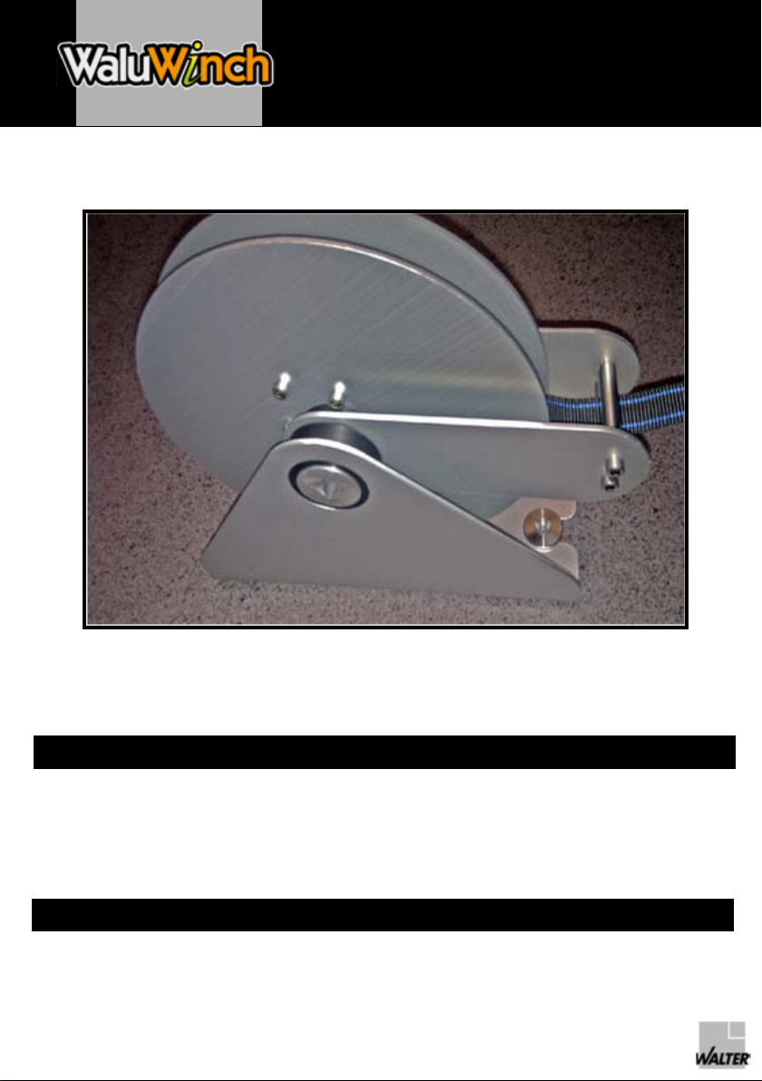
Den Gurt zum Einholen der Abdeckung ca. 50 cm in der Führung zwischen
dem runden Teil und der Krone der Abrollvorrichtung gleiten lassen.
Den Vierkant der Aufrollvorrichtung oder der Handkurbel in den zentralen Teil
der dazu vorgesehenen Krone einlegen.
Die diversen Befestigungen der Abdeckung anbringen, um Konformität mit der
Norm NF P 90-308 herzustellen.
3
4
5
6
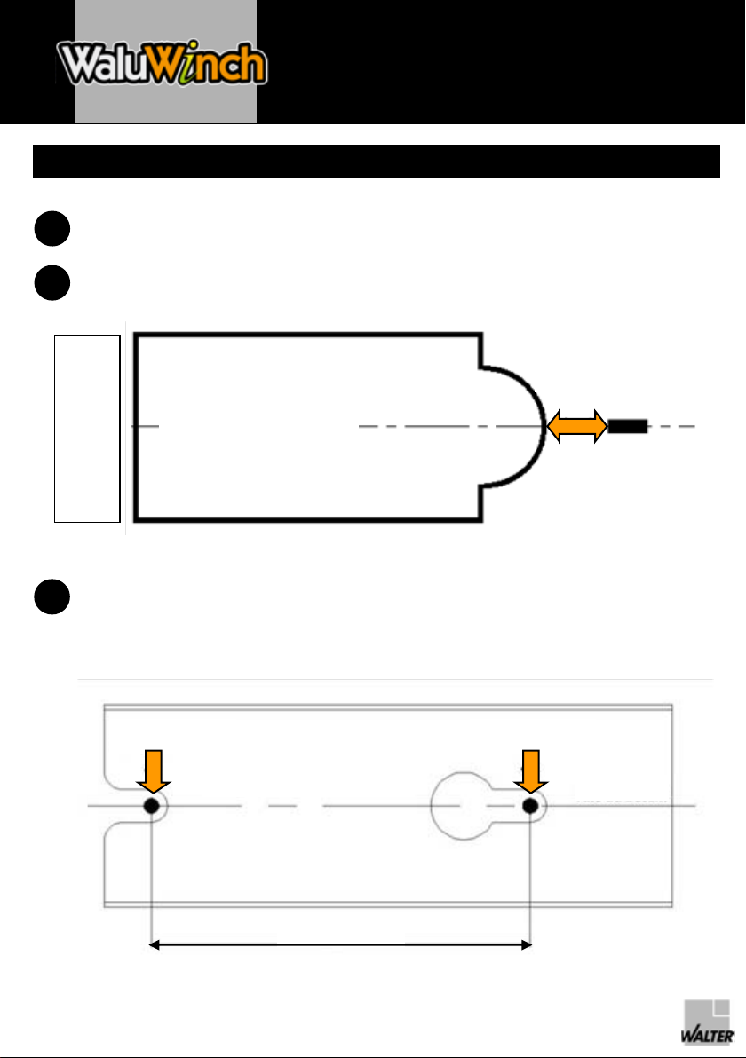
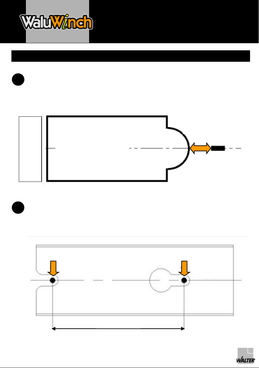
Bei unebenem Boden (siehe Skizze) zum Ausfüllen der Hohlräume die
mitgelieferten Scheiben einlegen.
Optional ist eine Edelstahl-Platte ZA100093 erhältlich, die zwischen Boden
und Verriegelungsansatz platziert wird.
Boden
Verriegelungsansatz
SEHR WICHTIG: Niemals die Abdeckung mit der Abrollvorrichtung
spannen.

Montageanleitung
SICHERHEITS-TIPPS
GARANTIE
Beim
Auf-
und
Abrollen
der Abdeckung
ist
das
Becken
stets
im
Auge zu
halten.
Das
Aufrollen
der Abdeckung
ist
durch
einen
verantwortlichen
(befugten
)
Erwachsenen
vorzunehmen.
Auf
der Abrollvorrichtung
Walu
Winch leisten
wir
1 Jahr
Garantie.
Der Kundendienst
wird
in erster
Linie
durch
Ihre
Vertriebsfirma
wahrgenommen.

FR
DEGB
IT
NLSE
PL
ES
PT
Unwinding
system
for bar supported
safety
covers
Fitting
instructions
Safety
recommendations
Warranty

Cover storage
side
Fitting instructions
INSTALLATION AND UNWINDING
Using
the screws
and plugs
provided, fix
the stud
to the ground.
Position: in the centre of the pool width, on the tiling, on the winding
side,
about 1 m from
the edge
of the pool or steps.
Depending
on the condition of the pool deck, a second stud
(supplied) may
be
necessary
(distance between
the two
: 200 mm, see
sketch).
Drill a screw
hole
diameter
8 mm x 60 mm deep.
1
2
Axis of pool
Distance between
1 and 1.2m
Axis of pool
1st
hole 2nd
hole
200 mm

Fitting instructions
Fasten
the unwinder
by slotting
the hole
onto the stud.
Slide
about 50 cm of the cover
pulling
strap
into
the guide, between
the round
pin and the hub of the unwinder
crown.
Insert the square pin on the carriage
or handle
into
the slot provided
in the
central part of the crown.
Fit the cover
fastenings
so
that
the cover
complies with
standard NF P 90-308.
3
4
5
6
If the ground
is
uneven
(see
sketch), insert the shims
provided
to make
up the
gaps.
An optional
stainless
steel
plate ZA100093 is
available
to place between
the
ground
and the fastening
stud.
VERY IMPORTANT: never
tighten
the cover
using
the unwinder.
Level
0 of the
fastening
stud
Ground
level
0

Fitting instructions
SAFETY RECOMMENDATIONS
WARRANTY
Always
keep
an eye
on the pool while
opening
or closing
the pool cover.
The cover
must only
be
wound
by a responsible
adult.
The Walu
Winch unwinding
system is
guaranteed
for 1 year.
For the after
sales service, contact your
dealer first.

Istruzioni
di montaggio
Consigli
di sicurezza
Garanzie
FR
DEGB
IT
NLSE
PL
ES
PT
Sistema di svolgimento
per coperture a barre

Distance entre 1 et
1,20 m
Lato di
stoccaggio
Istruzioni di montaggio
INSTALLAZIONE E SVOLGIMENTO
Fissare il perno utilizzando le viti e i tasselli appositamente forniti.
Posizionamento: al centro della vasca nel senso della larghezza,
sul
rivestimento, lato avvolgimento, a circa 1m dal bordo della vasca o dalla
scala.
In funzione dello stato del bagnasciuga e se necessario, utilizzare anche il
secondo perno in dotazione (distanza fra i due perni 200 mm, vedere il
disegno).
Diametro di foratura 8 mm x 60 mm di profondità.
1
2
Asse della vasca
Distanza
compresa fra
1 e 1,20m
Asse della vasca
Foratura
n°2 Foratura
n°1
200 mm

Istruzioni di montaggio
Ancorare lo svolgitore per mezzo del perno.
Infilare per circa 50 cm la cinghia di richiamo della copertura nella guida, fra il
tondino e la corona dello svolgitore.
Inserire la barretta quadra del carrello o della manovella nella
parte centrale
dell'apposita corona.
Provvedere ai vari fissaggi della copertura, attenendosi alla norma NF P 90-
308.
3
4
5
6
Se il terreno non è
livellato (vedere disegno), inserire le rondelle
appositamente fornite per compensare le cavità.
È
disponibile i opzione una piastra in acciaio inox ZA100093 da disporre fra il
suolo e il perno di bloccaggio.
Livello 0
del perno
di bloccaggio
IMPORTANTISSIMO: non tendere mai la copertura utilizzando lo
svolgitore.
Livello 0
del suolo

Istruzioni di montaggio
CONSIGLI DI SICUREZZA
GARANZIE
Non perdere
mai di vista la vasca
durante
le operazioni
di apertura
e di chiusura
della
copertura.
L’avvolgimento
della
copertura
deve
essere
effettuato
da un adulto
responsabile.
Lo svolgitore Walu
Winch è
garantito
1 anno.
L’assistenza
post-vendita
è
una
garanzia
prioritaria
del
rivenditore
di fiducia.

Montageinstructie
Veiligheidsinstructies
Garantie
FR
DEGB
IT
NLSE
PL
ES
PT
Afrolsysteem
voor zwembaddekken met stangen

Opslag
kant
Montageinstructie
INSTALLATIE EN UITROLLEN
De pin bevestigen
met behulp
van de meegeleverde
schroeven
en pluggen.
Plaatsing: in het
midden
van de zwembadbreedte, op de tegels, aan
de
oprolkant, op ongeveer
1 m van de rand van het
zwembad
of de trap.
Volgens
de staat
van het
strand
en indien nodig
wordt
een
tweede
pin
geleverd
(afstand
tussen
beide
pinnen
ongeveer
200 mm, zie
de tekening).
Boordiameter
8 mm x 60 mm diepte.
1
2
As van het bad
Afstand van
1 tot 1,20m
As van het bad
Boor nr.
2Boor
nr. 1
200 mm

Montageinstructie
Bevestig
de afroller
met behulp
van de pin.
Glijd
de belastingband
van het
dek
ongeveer
50 cm in de geleider, tussen
het
rond en de kroon
van de afroller.
Plaats
het
vierkant
van de wagen
of de slinger
in het
middelste
gedeelte
avn
de kroon
dat
hiervoor
is
voorzien.
Plaats
de verschillende
bevestigingen
van het
dek, zodat
dit voldoet
aan
de
norm
NF P 90-308.
3
4
5
6
Bij
een
ongelijke
grond
(zie
tekening) gebruikt
u de meegeleverde
ringetjes
om het
verschil
op te vangen.
Een
rvs
plaat
ZA100093 om tussen
de grond
en de vergrendelingspin
te
plaatsen
is
beschikbaar
als
optie.
Grond
Vergrendelingspin
BIJZONDER BELANGRIJK: trek het
dek
nooit
strak
met behulp
van de
afroller.

Montageinstructie
VEILIGHEIDSINSTRUCTIES
GARANTIE
Houd
het
zwembad
altijd
in het
oog
tijdens
het
openen
en sluiten
van de afdekking
Het
oprollen
van de afdekking
moet
door
een
verantwoordelijke
volvassene
worden
uitgevoerd.
De afroller
de déroulement Walu
Winch heeft
een
garantie van 1 jaar.
De klantenservice
wordt
in eerste
instantie
door
uw
verkoper
verzorg.
Table of contents
Languages:
Other Walter Industrial Equipment manuals