wantai DQ860MA User manual

Changzhou Wantai Electrical Appliance Co., Ltd
Introduction:
DQ860MA is a type of two-phase hybrid stepping motor driver, The drive voltage of which is
from 24VDC to 80VDC. It is designed for use with 2-phase hybrid stepper motor of all kinds with
57mm to 110mm outside diameter and less than 7.8A phase current. This circuit that it adopts is
similar to the circuit of servo control which enables the motor running smoothly almost without
noise and vibration. Holding torque when DQ860MA runs under high speed, is also significantly
higher than the other two-phase driver, what’s more, the positioning accuracy is also higher. It is
widely used in middle and big size numerical control devices such as curving machine, CNC
machine, and computer embroider machine, packing machines and so on.
Features:
l High performance, low price
l Average current control, 2-phase sinusoidal output current drive
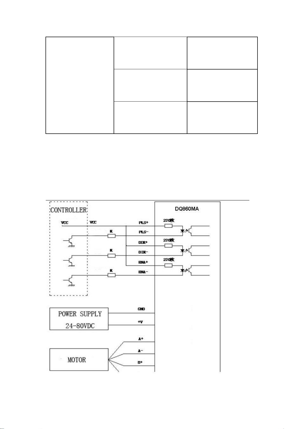
l Supply voltage from 24VDC to 80VDC
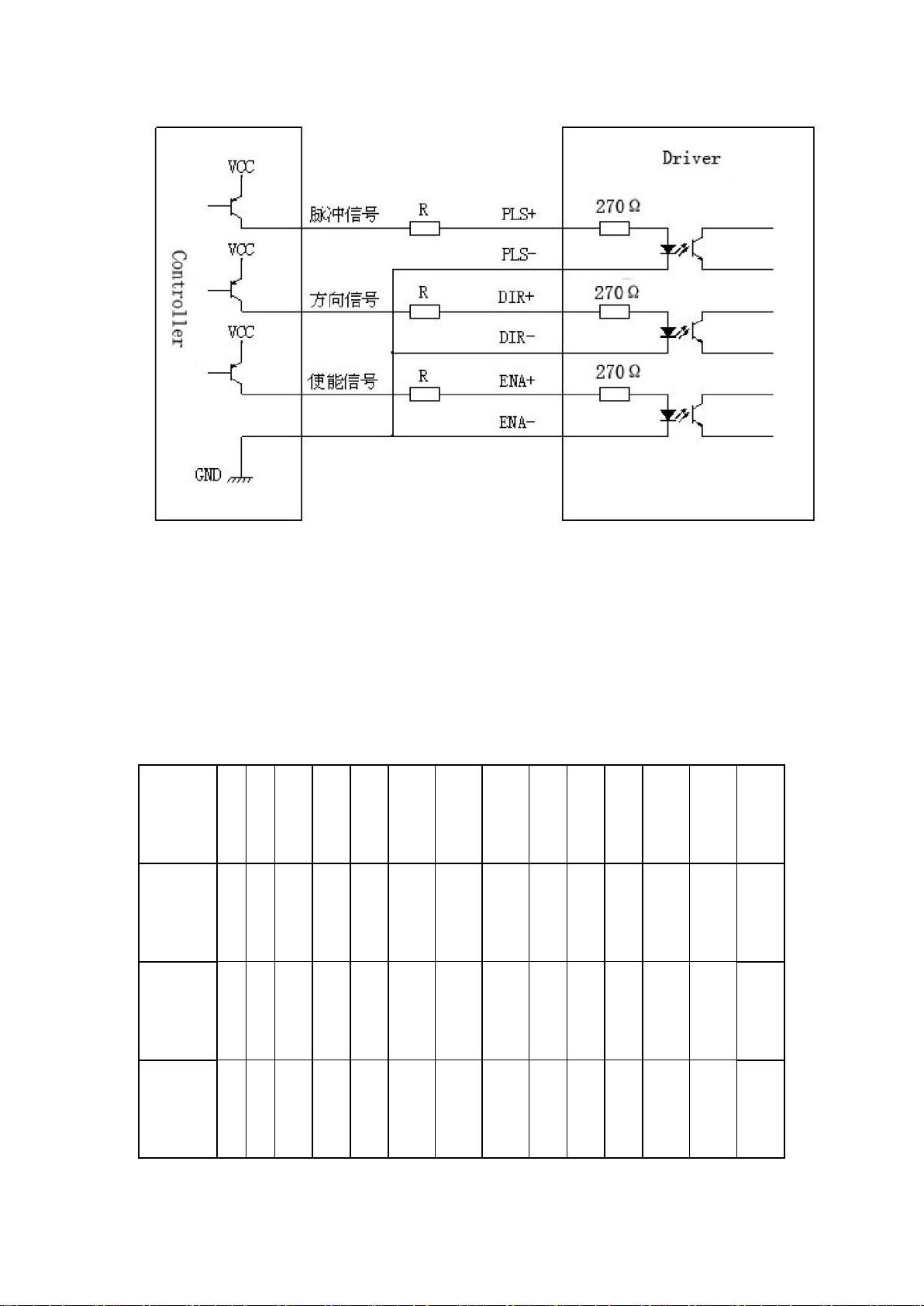
l Opto-isolated signal I/O
l Overvoltage, under voltage, over-current, phase short circuit protection
l 14 channels subdivision and automatic idle-current reduction
l 8 channels output phase current setting
l Offline command input terminal
l Motor torque is related to speed, but not related to step/revolution
l High start speed
l High holding torque under high speed
Electrical specification:
Input voltage
24-80VDC
Input current
<6A
Output current
2.8A~7.8A
Consumption
Consumption:80W;Internal
Insurance:10A

Temperature
Working Temperature -10~45℃;
Stocking temperature -40℃~70℃
Humidity
Not condensation, no water droplets
gas
Prohibition of combustible gases and
conductive dust
weight
600GS
Pins assignments and description:
1) Connector Pins Configurations
Pin
Function
Details
PUL
+,PUL-
Pulse signal, PUL+ is the positive end of pulses input pin
PUL- is the negative end of pulse input pin
DIR+,DIR
-
DIR signal: DIR+ is the positive end of direction input pin
DIR- is the negative end of direction input pin
ENBL+
Enable signal: ENBL+ is the positive end of direction input
pin. This signal is used for enabling/disabling the driver. High
level for enabling the driver and low level for disabling the
driver.
ENBL-
ENBL- is the negative end of direction input pin. Usually left
unconnected (enabled)

2) Pins wiring diagram:
PC’s control signals can be active in high and low electrical level. When the high electrical level is
active, all control negative signals will be connected together to GND. When low electrical level is
active, all control positive signals will be connected together to public port. Now give two
examples( Open collector &PNP), please check them:
Fig 1. Input port circuit (Yang connection)
PC open connector output

Fig. 2 Input port circuit ( Yin connection)
PC PNP output
Note: When VCC=5V, R=0
When VCC=12V, R=1K, >1/8W
When VCC=24V, R=2K,>1/8W
R must connect in the control signal part .
3.Function choice ( Using DIP pins to achieve this function)
1) Micro step resolution is set by SW 5,6,7,8 of the DIP switch as shown in the following table:
SW5
O
N
OF
F
ON
OF
F
ON
OFF
ON
OFF
ON
OF
F
ON
OFF
ON
OFF
SW6
O
N
O
N
OF
F
OF
F
ON
ON
OFF
OFF
ON
ON
OF
F
OFF
ON
ON
SW7
O
N
O
N
ON
ON
OF
F
OFF
OFF
OFF
ON
ON
ON
ON
OFF
OFF
SW8
O
N
O
N
ON
ON
ON
ON
ON
ON
OF
F
OF
F
OF
F
OFF
OFF
OFF

PULSE/
REV
40
0
80
0
16
00
32
00
64
00
128
00
256
00
512
00
10
00
20
00
50
00
100
00
250
00
500
00
2) Standstill current setting
SW4 is used for this purpose. OFF meaning that the standstill current is set to be half of the
selected dynamic current and ON meaning that standstill is set to be the same as the selected
dynamic current.
3) Output current setting:
The first three bits (SW 1, 2, 3)of the DIP switch are used to set the dynamic current. Select a
setting
Closest to your motor’s required current
Output current (A)
SW1
SW2
SW3
PEAK
RMS
ON
ON
ON
2.80
2.00
OFF
ON
ON
3.50
2.50
ON
OFF
ON
4.20
3.00
OFF
OFF
ON
4.90
3.50
ON
ON
OFF
5.70
4.00
OFF
ON
OFF
6.40
4.60
ON
OFF
OFF
7.00
5.00
OFF
OFF
OFF
7.80
5.60
4) Semi-flow function:
Semi-flow function is that there is not step pulse after200 ms, the driver output current
automatically reduced to 40% of rated output current, which is used to prevent motor heat.
4. Pins of motor & power:
Motor
1
A+
Motors wiring

and
power
pins
2
A-
3
B+
4
B-
5,6
DC+
DC-
Power supply
Power supply :
DC24-80VDC
The peak input current
can not up to 6A
5. Mechanical Specification:
To have 20mm of space around ,cannot be placed next to other heating devices. What’s more,
avoid dust, oil mist, corrosive gas, heavy humidity and high vibration. (Unit=mm)
6. Adjustment of troubleshooting

1) , the status on light’s indication
PWR: green, normal work light.
ALM: red, failure light, the motor with phase short-circuit, overvoltage and under-voltage
protection.
2) Troubles
Alarm indicator
Reasons
Measures
LED off turn
Wrong connection for
power
Check wiring of power
Low-voltages for power
Enlarge voltage of
power
Motor doesn’t run,
without holding
torque
Wrong connection of
stepper motor
Correct its wiring
RESET signal
is effective when
offline
Make RESET
ineffective
Motor doesn’t run,
but maintains holding
torque
Without input pulse
signal
Adjust PMW & signal
level
Motor runs wrong
direction
Wrong wires’
connection
Change connection for
any of 2 wires
Wrong input direction
signal
Change direction
setting
Motor’s holding
torque is too small
Too small relative to
current setting
Correct rated current
setting

Acceleration is too fast
Reduce the
acceleration
Motor stalls
Rule out mechanical
failure
Driver does not match
with the motor
Change a suitable
driver
7. Driver wiring
A complete stepper motor control system should contain stepper drives, DC power supply and
controller (pulse source). The following is a typical system wiring diagram

8. APPENDIX
Twelve Month Limited Warranty
WANTAI MOTOR. warrants its products against defects in materials and workmanship for a
period of 12 months from shipment out of factory .During the warranty period, WANTAI MOTOR
will either ,at is option, repair or replace products which proved to be defective.
9. Exclusions
The above warranty does not extend to any product damaged by reasons of improper or
inadequate handlings by customer, improper or inadequate customer wirings, unauthorized
modification or misuse .or operation beyond the electrical specifications of the product and/or
operation beyond environmental specifications for the product.
10. Obtaining Warranty Service
To obtain warranty service, a returned material authorization number(RMA)must be obtained
from customer service at e-mail:
sales@wantmotor.com.Before returning product for service. Customer shall prepay shipping
charges for products returned to WANTAI MOTOR for warranty service, and WANTAI MOTOR
shall pay for return of products to customer.
11. Warranty Limitations
WANTAI MOTOR makes no other warranty, either expressed or implied, with respect to the
product. WANTAI MOTOR specifically disclaims the implied warranties of merchantability and
fitness for a particular purpose. Some jurisdictions do not allow limitations on how long and
implied warranty lasts .so the above limitation or exclusion may to apply to you, however, any
implied warranty of merchantability or fitness is limited to the12-month duration of this written
warranty.
Table of contents