Wareforce DG-E Setup guide

WAREFORCE SERIES
GLASSWASHER
DISHMACHINES
INSTALLATION, OPERATION,
AND SERVICE MANUAL
FOR WAREFORCE MODEL:
DG-E
WAREFORCE DG-E Manual • 07610-003-67-17-K

Revision
Letter
Revision
Date Made by Applicable ECNs Details
A 3-5-09 RC N/A Release to Production.
10 8-20-09 ARL QOF-339 Updated programming page diagram.
B 6-9-10 RC 100609-1502-
CW
Removed warranty registration information.
C 5-22-12 RC QOF-386 Updated schematic to reect wiring change at door switch.
D 3-11-13 RC QOF NDB-219 Updated company logo. Updated pump assembly page.
E 1-28-14 MHH QOF NDB-219 Added wiring change schematics.
F 3-19-14 MHH ECN 8293 Removed page on programming chemical feeder pumps.
Updated drawings for control box assembly, motor & pump assembly and
incoming plumbing assembly.
Added schematics and harness connections.
G 12-15-15 JH N/A Removed DG-D and all references to it.
Changed P/N 05330-100-01-10 to 05330-011-61-34, item #3
on pg. 32.
H 4-22-16 JH N/A Changed drain connection information to 2 1/2” and changed
NPT to “No Hub Connection” on pg. 2.
J 5-9-16 JH ECN 8380 Changed Booster Tank Assembly view and applicable P/Ns to
show thermostat change, pg. 32.
Added schematic 09905-003-36-56-E to show thermostat
change, pg. 37. Removed earlier versions.
Changed Harness Connections diagram to show thermostat
change, pg. 38.
K 1-5-17 JH N/A Updated to new manual format.
Audited and corrected all P/Ns in the manual.
REVISION HISTORY

ii
DG-E
Glasswasher dishmachine; low-temperature, chemical-
sanitizing, with a booster tank and detergent, rinse-aid,
and sanitizer chemical feeder pumps.
Model:
Serial No.:
Installation Date:
Service Rep. Name:
Phone Number:
The manufacturer provides
technical support for all of
the dishmachines detailed
in this manual. We strongly
recommend that you refer to
this manual before making a call
to our technical support staff.
Please have this manual with
you when you call so that our
staff can refer you, if necessary,
to the proper page. Technical
support is not available on
holidays. Contact technical
support toll free at
1-888-800-5672.
Technical support is available
for service personnel only.
NOMENCLATURE

iii
GUIDES
Symbols .......................................................................................................................1
Abbreviations & Acronyms ..........................................................................................1
SPECIFICATIONS
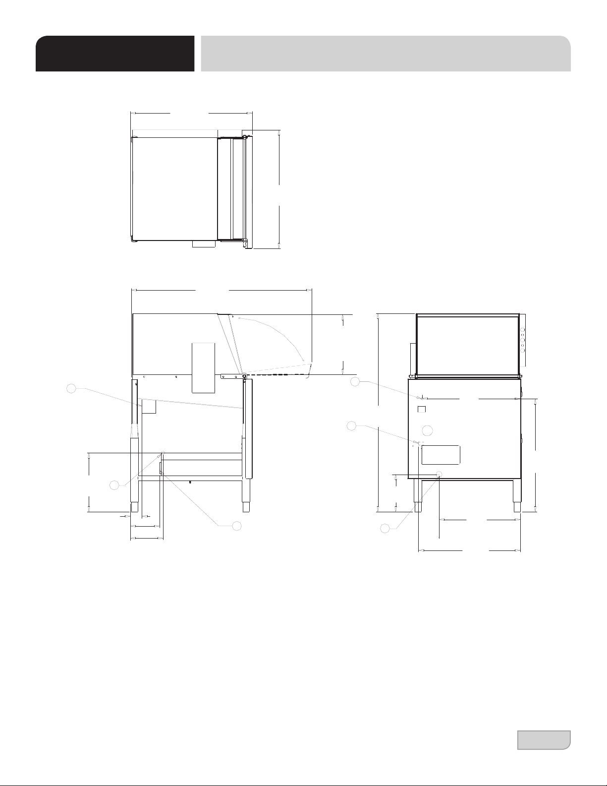
Machine Dimensions ...................................................................................................2
Operating Specs..........................................................................................................3
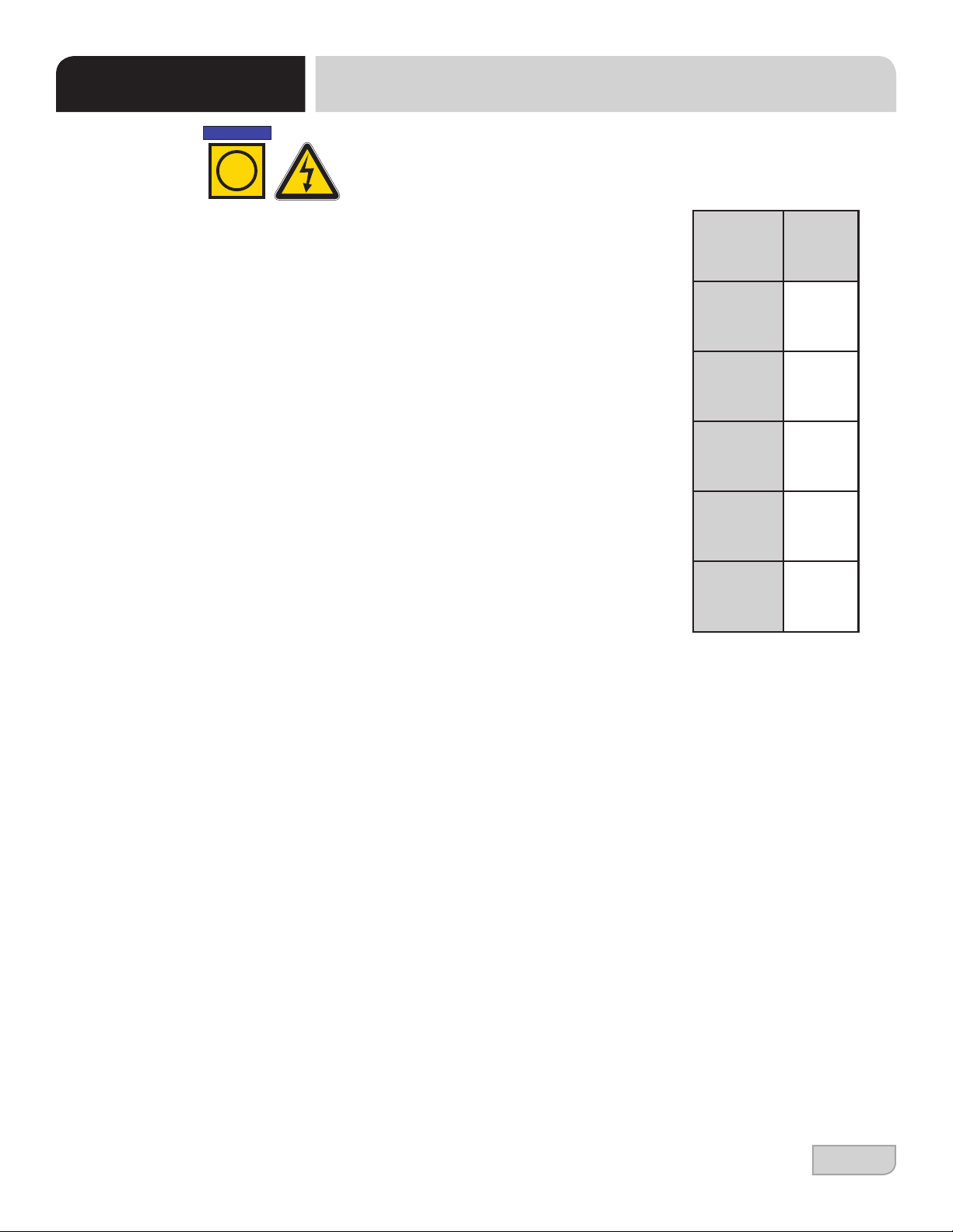
Electrical Requirements...............................................................................................4
INSTALLATION
Installation Instructions ................................................................................................5
Inspection..........................................................................................................5
Unpacking .........................................................................................................5
Leveling.............................................................................................................5
Plumbing ...........................................................................................................5
Pressure Regulator...........................................................................................6
Shock Absorber ................................................................................................6
Drain Line .........................................................................................................6
Plumbing Check................................................................................................6
Electrical Power Connections ...........................................................................7
Voltage Check ..................................................................................................7
Surrounding Area..............................................................................................7
Temperature Setpoints .....................................................................................7
Chemical Feeder Equipment ............................................................................8
Priming Chemical Feeder Pumps.....................................................................8
OPERATION
Operation Instructions .................................................................................................9
Preparation .......................................................................................................9
Power Up ..........................................................................................................9
Initial Start-up....................................................................................................9
Ware Preparation..............................................................................................11
Daily Start-up ....................................................................................................11
Washing a Rack of Ware..................................................................................11
Operational Inspection......................................................................................12
Shutdown & Cleaning .......................................................................................12
Detergent Control ........................................................................................................13
Deliming.......................................................................................................................14
TABLE OF CONTENTS

iv
TABLE OF CONTENTS
MAINTENANCE
Preventative Maintenance ...........................................................................................15
TROUBLESHOOTING
Common Problems......................................................................................................16
PARTS SECTION
Control Box Assembly .................................................................................................18
Chemical Feeder Pump Components .........................................................................21
Peri-pump Box Assembly ............................................................................................22
Electrical Connection Box Assembly...........................................................................23
Frame Assembly..........................................................................................................24
Hood Assembly ...........................................................................................................25
Switch Panel Assembly ...............................................................................................26
Tub Assembly..............................................................................................................27
Frame & Motor Assembly............................................................................................30
Motor Assembly...........................................................................................................32
Booster Assembly........................................................................................................33
Inlet Plumbing..............................................................................................................34
Plumbing Options ........................................................................................................35
Solenoid Valve Repair Kits..........................................................................................36
Door Assembly ............................................................................................................37
Front Panel Assembly .................................................................................................38
SCHEMATICS
DG-E 115 V, 60 Hz, 1-Phase ......................................................................................39
DG-E Harness Connections ........................................................................................40

07610-003-67-17-K
1
GUIDES GUIDES
SYMBOLS
!
CAUTION
!
WARNING
NOTICE
- risk of injury to personnel.
- risk of damage to equipment.
- risk of electrical shock.
- lockout electrical power.
- reference data plate.
- important note.
i
- caustic chemicals.
ABBREVIATIONS & ACRONYMS
ANSI - American National Standards Institute
GHT - Garden Hose Thread
GPM - Gallons per Minute
GPG - Grains per Gallon
HP - Horse Power
Hz - Hertz
ID - Inside Diameter
kW - Kilowatts
NFPA - National Fire Protection Association
NPT - National Pipe Thread
PSI -Pounds per Square Inch
V- Volts
- ground wire.

07610-003-67-17-K
2
Delta 5-E Installation, Operation, and Service Manual 07610-003-37-08-J
Issued: 05-25-2007 Revised: 05-09-16
SECTION 1: SPECIFICATION INFORMATION
DIMENSIONS
3
21 1/4
(540 mm)
17
(432 mm)
20
(508 mm)
C
A
21 1/4
(540 mm)
B
7 3/4
(197 mm)
39
(991 mm)
6 3/4 (171 mm)
6 (152 mm)
12 1/4
(311 mm)
36 3/4
(933 mm)
24 1/2
(622 mm)
25 1/4
(642 mm)
C
A
B
3 (76 mm)
A - Incoming Water Connection
B - Drain Connection - 2" IPS
C - Electrical Connection Point
NOTE: All vertical dimensions are
at lowest point due to adjustable
bullet feet and may be raised an
additional 2 3/4".
11 1/2
(292 mm)
DISH
CLEARANCE
FRAME DIMENSIONS
Width...................................................................................................... 24 1/2” (622 mm)
Depth .....................................................................................................25 1/4” (641 mm)
Depth with Front Door Open ................................................................. 36 3/4” (933 mm)
Height ....................................................................................................39” (990 mm)
Maximum Wash Chamber Clearance ................................................... 11 1/2” (292 mm)
MACHINE DIMENSIONS
SPECIFICATIONS
A - Incoming Water Connection
B - Drain Connection - 2” NPT
C - Electrical Connection Point
All dimensions from the oor can be
increased 2 3/4” with the machine’s
adjustable feet.
”
”
”
”
”
”
”
”
”
”
”
”
”
”

07610-003-67-17-K
3
OPERATING SPECS
SPECIFICATIONS
Operating Capacity:
Racks per Hour 29
Dishes per Hour 725
Glasses per Hour 1440
Gallons per Rack 1.24
Gallons per Hour 36
Operating Cycles (Seconds):
Wash Time 46
Rinse Time 25
Dwell Time 21
Total Cycle Time 92
Wash Tank Capacity (Gallons): 1.2
Water Temperatures (°F):
Minimum Wash Temperature 120
Minimum Rinse Temperature 120
(140 °F is recommended for both.)
Other Water Requirements:
Water Line Size (NPT) 1.2"
Drain Line Size (NPT) 2"
Flow Pressure (PSI) 20 A 5
Minumum Chlorine Required (PPM): 50
NOTE: Always refer to the machine data plate for specic electrical and water
requirements. The material provided on this page is for reference only and is
subject to change without notice.
OPERATING SPECS
NOTICE
i

07610-003-67-17-K
4
Electrical Requirements:
Wash Motor HP 0.75
Wash Heater kW 1.5
Rinse Heater kW 2 kW @ 110 V
Total Amps 16*
Typical Electrical Circuit (Amps) 20
All electrical ratings provided in this manual are for reference only. Always refer
to the machine data plate to get exact electrical information for this machine.
All electrical work performed on machines should be done in accordance
with applicable local, state, territorial, and national codes. Work should
only be performed by qualied electricians and authorized service agents.
Note that all electrical wiring used in this series of machines must be rated,
at a minimum, for 212 °F (100 °C), and that only copper conductors must be
used.
Where applicable, heating element amperage draws have been adjusted for
the assumed input voltage. The manufacturer assumes incoming voltages will
be either 208 or 230 V. Some heating elements used in the machines are rated
for other voltages, such as 240 V and 480 V. Always verify the amperage draw
of the machine in operation when sizing circuit protection.
If the dishmachine is equipped with the optional rinse heater, note the rinse
heater might have its own electrical connection and require a separate service.
Amperage loads for motors and heaters are indicated on the machine data plate.
DG-E electrical congurations:
Available Electrical Characteristics:
• 115 V, 60 Hz, Single-phase
Available Wash Tank Heaters:
• 1.5 kW
Available Rinse Tank Heaters:
• 2 kW
*The DG-E is designed so that the wash motor is never running when the
wash heater is on. Total Amps is based on the higher of the two loads.
DG-E
Electrical Characteristics
VOLTS 115
PHASE 1
FREQ 60
WASH
MOTOR
AMPS
10.0 A
WASH
HEATER
AMPS
16.0 A
TOTAL
LOAD 16.0 A*
NOTICE
i
ELECTRICAL REQUIREMENTS
SPECIFICATIONS

07610-003-67-17-K
5
Before installing the unit, check packaging and machine for damage. Damaged
packaging might be an indication of damage to the machine. If there is any type
of damage to both packaging and unit, do not throw away the packaging. The
dishmachine has been inspected at the factory before shipping and is expected to
arrive in new, undamaged condition. However, rough handling by carriers or others
might result in damage to the unit while in transit. If this occurs, do not return the unit to
the manufacturer. Instead, contact the carrier and ask them to send a representative
to the site to inspect the damage and request that an inspection report be completed.
Contact the carrier within 48 hours of receiving the machine as well as the dealer that
sold you the unit.
The machine should be unpacked and removed from the pallet before installing. Open
the front door and remove all of the materials from inside. Once unpacked, verify there
are no missing parts. If a part is missing, contact the manufacturer immediately.
The dishmachine is designed to operate while level. This is important to prevent any
damage to the machine during operation and to ensure the best results possible.
The unit comes equipped with adjustable bullet feet which can be turned using a
pair of pliers. Verify the unit is level from front-to-back and side-to-side before
making any electrical or plumbing connections.
All plumbing connections must be made to adhere to local, state, territorial, and
national codes. The installing plumber is responsible for ensuring the incoming
water lines are ushed of debris before connecting to the machine. Note that chips
and materials from cutting processes can become lodged in the solenoid valves
and prevent them from opening or closing. Any valves that are found to be fouled
or defective because of foreign matter left in the water line, and any subsequent
damage, are not the responsibility of the manufacturer.
A water hardness test must be performed. If water hardness is higher than 5 GPG,
install a water softener or install the optional HTS-11 (scale prevention and corrosion
control). Please contact the manufacturer to purchase the HTS-11.
INSTRUCTIONS
INSTALLATION
INSPECTION
LEVELING
UNPACKING
PLUMBING
Do not throw away
packaging if damage is
evident!
A water hardness test
must be performed.
The plumber must ush
the incoming water line!
!
CAUTION

07610-003-67-17-K
6
WATER SUPPLY
CONNECTIONS:
WATER HARDNESS
HIGHER THAN
5 GPG
WATER SUPPLY
CONNECTION:
WATER HARDNESS
OF 5 GPG
OR LOWER
PRESSURE
REGULATOR
SHOCK ABSORBER
DRAIN LINE
PLUMBING CHECK
If water hardness is higher than 5 GPG and a water softener is not being used, install
the HTS-11 into the water line (1/2” ID pipe size minimum) before the dishmachine’s
incoming water connection point using copper pipe. Observe proper inlet/outlet water
directions. Flow directions are molded into the top of the head. It is recommended
that a water shut-off valve be installed before installing the HTS-11 to allow access for
service. Plumb from the HTS-11 outlet to the incoming water connection point using
copper pipe (or order the 1/2” ID exible hose kit offered by manufacturer).
If water hardness tests at 5 GPG or less, install the water supply line (1/2” ID pipe
size minimum) to the dishmachine’s incoming water connection point using copper
pipe (or order the 1/2” ID exible hose kit offered by manufacturer). It is recommended
that a water shut-off valve be installed in the water line between the main supply and
the machine to allow access for service.
The manufacturer has an optional water pressure regulator (see “Plumbing Options”
page) to accommodate areas where water pressure uctuates or is higher than the
recommended pressure. Take care not to confuse static pressure with ow pressure:
static pressure is line pressure in a “no ow” condition (all valves and services are
closed); ow pressure is the pressure in the ll line when the valve is opened during
the cycle.
It is suggested that the optional shock absorber (see “Plumbing Options” page) be
installed on the incoming water line. This prevents water hammer (hydraulic shock)
from causing damage to the equipment.
This dishmachine drain requires a minimum 2” NPT piping that is pitched at least 1/4”
per foot. There must also be an air-gap between the machine drain line and the floor
sink or drain. If a grease trap is required by code, it should have a flow capacity of
5 GPM.
After installing the incoming ll line and drain line, slowly turn on the water supply to
the machine. Check for any leaks and repair as required. All leaks must be
repaired before operating the machine.
Take care not to confuse
static pressure with
ow pressure.
INSTRUCTIONS
INSTALLATION

07610-003-67-17-K
7
Ground Lug
Power Block
INSTRUCTIONS
INSTALLATION
Electrical and grounding conductors must comply with the applicable portions of the
National Electric Code ANSI/NFPA 70 (latest edition) and/or other electrical codes.
The data plate is located at the front-left of the dishmachine. Refer to the data plate for
machine operating requirements, machine voltage, total amperage, and serial number.
Remove the connection box lid to install the incoming power lines. Install 1/2” conduit
into the pre-punched holes in the back of the control box. Route power wires and
connect to power block and grounding lug. Install the service wires to the appropriate
terminals as they are marked on the terminal block. Install the grounding wire into
the lug provided. It is recommended that “DE-OX” or
another similar anti-oxidation agent be used on all
power connections.
Apply power to the dishmachine. Check the incoming power at the terminal block
and ensure it corresponds with the voltage listed on the data plate. If not, contact a
qualied service agency to examine the problem. Do not run dishmachine if voltage
is too high or too low. Shut off the service breaker and advise all proper personnel
of the location of the breaker and any problems. Replace the connection box lid and
tighten-down the screws.
This is a commercial dishmachine and reaches temperatures that can exceed those
generated by a residential machine. Therefore, any surrounding countertops, cabinets,
ooring material, and suboor material must be designed and/or selected with these
higher temperatures in mind.
NOTE: Any damage to surrounding area that is caused by heat and/or moisture
to materials that are not recommended for higher temperatures will not be covered
under warranty or by the manufacturer.
The temperature setpoints on this unit have been set at the factory. They should
only be adjusted by an authorized service agent.
TEMPERATURE
SETPOINTS
SURROUNDING AREA
VOLTAGE CHECK
ELECTRICAL POWER
CONNECTIONS
Disconnect electrical
power at the breaker or
disconnect switch and
tag-out in accordance with
procedures and codes.
i
NOTICE

07610-003-67-17-K
8
This equipment is not recommended for use with deionized water or other aggressive uids.
Use of deionized water or other aggressive uids will result in corrosion and failure of
materials/components and will void the manufacturer's warranty.
The bottom of the chemical container cannot be located any higher than 8” from the
oor. If the unit is equipped with the 6” or 18” table stand, the highest position will be
14” or 26” from the oor, respectively.
This dishmachine is supplied with detergent, rinse-aid, and sanitizer chemical feeder
pumps.
Locate the open ends of the chemical tubes with the tube stiffeners and place each
one in the appropriate container.
A. Red Tubing = Detergent B. Blue Tubing = Rinse-aid
C. White Tubing = Sanitizer
Chemical feeder pumps need priming when the machine is rst installed or if the
chemical lines have been removed and air was allowed to enter.
1. Verify that the proper chemical tube stiffener inlet is in the proper container.
2. Use the prime switches located on the panel inside the door to prime each
pump. The switches are clearly marked with the type of chemical.
3. To prime the pumps, hold the switch until the chemical can be observed entering
the sump.
4. Detergent is dispensed as required during the wash cycle by the timer. The
amount of detergent might need to be adjusted depending on water quality and
type of detergent.
5. Rinse-aid is dispensed as required into the nal rinse. The amount of rinse-aid
might need to be adjusted depending on water hardness and results.
6. Sanitizer is dispensed into the final rinse. The amount of sanitizer might need to
be adjusted depending on the concentration.
CHEMICAL FEEDER
EQUIPMENT
PRIMING CHEMICAL
FEEDER PUMPS
WARNING: Some
dishwashing chemicals
might cause chemical
burns. Wear protective
gear when handling these
chemicals. If any skin
contact occurs, follow the
instructions provided
with the chemicals.
TO PREPARE
CHEMICAL FEEDER
PUMPS FOR
OPERATION
INSTRUCTIONS
INSTALLATION
!
WARNING
CAUTION: Chlorine-based
sanitizers can damage the
machine if the chemical
solution is too strong.
Contact the chemical
supplier for information.
!
CAUTION
CAUTION: Water must
be in the sump and wash
tank before dispensing
chemicals.
!
CAUTION

07610-003-67-17-K
9
INSTRUCTIONS
OPERATION
Before operating the unit, verify the following:
• The strainers are clean and in place.
• The drain stopper is installed.
• Wash/rinse arms are screwed securely into place and end-caps are tight.
• Wash/rinse arms rotate freely.
To energize the unit, turn on the power at the service breaker. The voltage should
have been previously veried as correct. If not, the voltage must be veried before
energizing the unit.
Before the heater element can be energized, the booster tank must be initially lled
with water.
1. Press and hold the FILL button until water overows into the wash strainer, then
release the button.
2. The booster tank is now lled with water.
3. Turn off the unit by pressing the ON/OFF button.
PREPARATION
POWER UP
INITIAL
START-UP
CAUTION: Damage to
the heater element will
occur if the element is not
submerged in water.
!
CAUTION

07610-003-67-17-K
10
After lling the booster tank, the heater element must be enabled. The machine is
shipped from the factory with the heater element disabled. This is done to ensure
that the heater element is not damaged by energizing the element without the
element being submerged in water. To enable the heater element:
1. Disconnect electrical power and remove the control box cover.
2. Connect the tagged white/blue wires.
3. Replace the control box cover and reconnect electrical power.
4. Press the ON/OFF button. The heater element will energize to maintain booster
heater temperature.
If the water level is not between the lines on the drain stopper, it will require
adjustment. Check to ensure that the recommended water pressure is being
supplied to the machine ( 20 A 5 PSI). If the water pressure is correct, the timer
needs adjustment. Use the following steps to adjust the ll time:
1. Remove the control box cover.
2. Adjust the left side of CAM 4. To raise the water level, increase (open) the notch
of the CAM; to lower the water level, decrease (close) the notch of the CAM.
3. Press and hold the START button until the cycle starts (about two seconds), run
a cycle, then check the water level.
4. Adjust as necessary then replace the control box cover.
The machine runs a complete cycle to drain and ll. If the machine fails to drain, the
water will build up inside the tub. After the initial ll, the rinse water for the current
cycle will mix with the wash water for the next cycle.
INSTRUCTIONS
OPERATION
INITIAL
START-UP
CAUTION: Water must
be in the sump while the
machine is running to
avoid running the pump
dry and causing damage
to the pump seal.
!
CAUTION
Disconnect electrical
power at the breaker or
disconnect switch and
tag-out in accordance with
procedures and codes.

07610-003-67-17-K
11
INSTRUCTIONS
OPERATION
WASHING A
RACK OF WARE
WARE
PREPARATION
DAILY
START-UP
Proper preparation of ware is essential for the smooth and efcient operation of the
dishmachine, resulting in fewer rewashes and less detergent used. Any ware loaded
inside the machine should have all solid food waste and scraps removed. Ware
should be sprayed-down before being placed in the dishmachine.
Place cups and glasses upside-down in racks so they do not hold water during the
cycle. Presoak atware in warm water to assist in removal of stuck-on material.
Load plates and saucers in the same direction.
1. Ensure the items in the Preparation section have been veried.
2. Ensure the chemical levels are correct.
3. Ensure the power is on and the tub has lled to the correct level.
4. Push the START button: the unit will start, run through the cycle, and shut off
automatically.
5. Repeat this two more times.
6. The unit is now ready for dishwashing.
1. Open the door.
2. Put a rack of ware into the machine.
3. Press and hold the START button until the cycle starts (about two seconds).
4. After cycle light goes off, the cycle is complete.
5. Open the door and remove the rack.

12
07610-003-67-17-K
INSTRUCTIONS
OPERATION
OPERATIONAL
INSPECTION
SHUTDOWN &
CLEANING
As the workday progresses, operators should regularly inspect the strainers to
ensure they have not become clogged. If the strainers become clogged, it will
reduce the washing capability of the machine.
1. Turn machine off by pushing ON/OFF button.
2. Remove the drain stopper and allow tub to drain.
3. Remove and clean the strainers.
4. Unscrew the wash/rinse arms from their manifolds.
5. Verify the nozzles and arms are free from obstruction. If clogged, remove end-
caps, clean nozzles with a brush, and flush with fresh water.
6. Replace end-caps and ensure they have been tightened.
7. Spray or wipe out interior of machine.
8. Replace wash/rinse arms.
9. Ensure all strainers are clean and securely in place.
10. Replace drain stopper.
11. Use stainless steel polish protect outside of dishmachine.

07610-003-67-17-K
13
INSTRUCTIONS
OPERATION
Detergent usage and water hardness are two factors that contribute greatly to how
efciently this dishmachine will operate. Using detergent in the proper amount can
become a source of substantial savings. A qualied water treatment specialist can
determine what is needed for maximum efciency from the detergent.
1. Hard water greatly affects the performance of the dishmachine, causing the
amount of detergent required for washing to increase. If the machine is installed
in an area with hard water, the manufacturer recommends the installation of
water treatment equipment.
2. Deposited solids from hard water can cause spotting that will not be removed
with a drying agent. Treated water will reduce this occurence.
3. Treated water might not be suitable for use in other areas of operation and it
might be necessary to install a water treatment unit for the water going to the
dishmachine only. Discuss this option with a qualied water treatment specialist.
4. Dishmachine operators should be properly trained on how much detergent is to
be used per cycle. Meet with a water treatment specialist and detergent vendor
to discuss a complete training program for operators.
5. This dishmachine requires that chemicals be provided for proper operation and
sanitization. Contact a chemical supplier with any questions.
6. Water temperature is an important factor in ensuring that the dishmachine
functions properly, and the machine's data plate details what the minimum
temperatures must be. If minimum requirements are not met, there is a possibility
that dishes will not be clean or sanitized.
7. Instruct dishmachine operators to observe the required temperatures and to
report when they fall below the minimum allowed. A loss of temperature can
indicate a larger problem.
DETERGENT
CONTROL
i

07610-003-67-17-K
14
In order to maintain the dishmachine at its optimum performance level, lime and
corrosion deposits must be removed. The frequency for deliming will be based on
water conditions. A deliming solution is available from your chemical supplier. Read
and follow all instructions on the label.
To delime the dishmachine:
1. Turn the machine on by pressing the ON/OFF button.
2. Press and hold the FILL button until water overflows into the wash strainer.
3. Add deliming solution per supplier’s instructions.
4. Close the door.
5. Flip the NORMAL/DELIME switch to DELIME.
6. Run machine the period of time recommended by chemical supplier.
7. Wait ve minutes, then inspect the inside of the machine. If the machine is not
delimed, run again.
8. Flip the NORMAL/DELIME switch to NORMAL.
9. Run two cycles to remove residual deliming solution.
DELIMING
NOTE: If this machine is
equipped with an
HTS-11 scale prevention
and corrosion control
device and lime is
becoming a frequent
problem, the cartridge
needs to be replaced.
To order a replacement
cartridge, call the
manufacturer.
INSTRUCTIONS
OPERATION

07610-003-67-17-K
15
PREVENTATIVE MAINTENANCE
MAINTENANCE
The manufacturer of this dishmachine highly recommends that any maintenance and
repairs not specically discussed in this manual be performed by qualied service
personnel only. Performing maintenance on the dishmachine may void a warranty.
By following the operating and cleaning instructions in this manual, users should get
the most efcient results from the dishmachine. As a reminder, here are some steps
to ensure that the dishmachine is used properly:
1. Ensure that the water temperatures match those listed on the machine data
plate (on the front-left of machine).
2. Remove as much soil as possible from ware before loading into racks.
3. Ensure that all strainers are in place and free of soil and debris before operating
the machine. To clean strainers, wipe them out with a rag and rinse under a
faucet. A toothpick can be used to dislodge any stubborn debris. Do not beat
strainers on waste cans; once bent they will not work properly.
4. If hard water is present, install a water softener or HTS-11 into the water line
connecting to the dishmachine (see "Plumbing the Dishmachine" section).
5. Ensure that all wash/rinse arms are secure in the machine before operating.
6. Ensure that the drain stopper is in place before operating.
7. Do not overll racks.
8. Ensure that glasses are placed upside-down in the rack.
9. Ensure that all chemicals being injected into the machine have been veried at
the correct concentrations.
10. Clean out the machine at the end of every workday per the "Shutdown and
Cleaning" section of this manual.
11. Always contact a qualied service agency whenever a serious problem arises.
12. Follow all safety procedures, whether listed in this manual or put forth by local,
state, or national codes/regulations.
PREVENTATIVE
MAINTENANCE
i
Table of contents
Other Wareforce Dishwasher manuals