Wareforce UL30 Setup guide

WAREFORCE SERIES
UNDERCOUNTER
DISHMACHINES
INSTALLATION, OPERATION,
AND SERVICE MANUAL
WAREFORCE UH30-FND
WAREFORCE UL30
WAREFORCE UH30-FND/UL30 Manual • 07610-004-37-37-P

i
REVISION HISTORY
Revision Date Made by Process Details
A 7-25-16 JH N/A Initial release of the manual.
B 3-6-17 JH N/A Added UL30 to manual. Updated pg. 42 with new motor and assembly P/Ns.
C 5-16-17 JH 8511
Updated water line connection information. Changed wording in chemical feeder pump
programming section to indicate changes are lost if closed without saving. Changed steps in
the Heater Contactor Wiring and Shutdown & Cleaning sections to be applicable to units with a
mechanical timer. Removed item #25 from pg. 47. Changed Discharge Hose to 05700-004-43-76
in the Wash Manifold Assembly. Added 05700-004-36-95 to UH30-FND Display page and corrected
the P/N for the Display Decal. Added a Plumbing Options page.
D 6-6-17 JH N/A Corrected draining procedure. Corrected wash motor amps for UL30 on Electrical Requirements
page. Updated UL30 schematic.
E 7-10-17 JH N/A Added 05940-002-78-97 to the UH30-FND Control Panel page.
F 7-25-17 JH N/A Changed Heater Contactor Wires (UH30-FND Only) section to show current process.
G 8-23-17 JH QOF-386
Replaced the middle 05975-003-35-21 with 05975-210-08-00 on the UH30-FND Control Panel
page. Corrected items 4 and 5 on UH30-FND Chemical Feeder Pump Assembly page to 1/8" clear
and added length. Added color and length to items 6 and 7 on UH30-FND Chemical Feeder Pump
Assembly page. Added the 100" chemical tubes for red, white, and blue to UL30 Chemical Feeder
Pump Assembly page.
H 2-20-19 JH 8585
8599
Updated pg. 2. Corrected references to ow pressure on pg. 6. Updated references to E and
F outputs on pgs. 9–10. Corrected part numbers of motor assembly and motor only on pg. 40.
Updated parts on pg. 42. Changed item #11 on pg. 46. Updated item #6 on pg. 50 and added link
to instructions. Added links to instructions on pg. 51.
J 6-19-20 JH 8709
19-680
Revised Programming Chemical Feeder Pumps section. Updated chemical feeder pump
assemblies. Revised UL30 control panel pages. Corrected drain hose P/N.
K 11-13-20 JH 8469 Revised drain line size. Updated dimensional drawing. Added mechanical timer instructions for
UL30. Updated timer P/N on pg. 25.
L 6-15-21 JH N/A Updated amp values of UL30. Changed P/N of high limit thermostat on UL30 Heater Components
page. Added UL30 oat to Miscellaneous Parts page.
M 5-11-22 JH 22-1201
22-1202
Removed water hardness test strip. Updated Chemical Feeder Pumps section with black dot roller
and corrected P/Ns and components. Added door magnet bracket to Door pages.
N 12-7-22 JH 8901
22-1505 Changed chemical tubing. Updated peri-pumps to black components.
P 5-16-23 JH 8905 New control panel, digital controls, door, kick panel, plumbing, rinse tank, and schematic for UH30-
FND.

ii
NOMENCLATURE
The manufacturer provides
technical support for all of
the machines detailed in
this manual. We strongly
recommend that you refer to
this manual before making a call
to our technical support sta.
Please have this manual open
when you call so that our sta
can refer you, if necessary, to
the proper page.
Technical support is not
available on holidays.
Contact technical support toll
free at 1-888-800-5672.
Technical support is available
for service personnel only.
WAREFORCE UH30-FND
Undercounter dishmachine; high-temperature, hot-water
sanitizing, with a booster tank and
detergent and rinse-aid chemical feeder pumps.
WAREFORCE UL30
Undercounter dishmachine; low-temperature with wash tank
heater, chemical-sanitizing, with detergent, rinse-aid, and
sanitizer chemical feeder pumps.

iii
TABLE OF CONTENTS
GUIDES
Symbols............................................................................................................................................ 1
Abbreviations & Acronyms ............................................................................................................... 1
SPECIFICATIONS
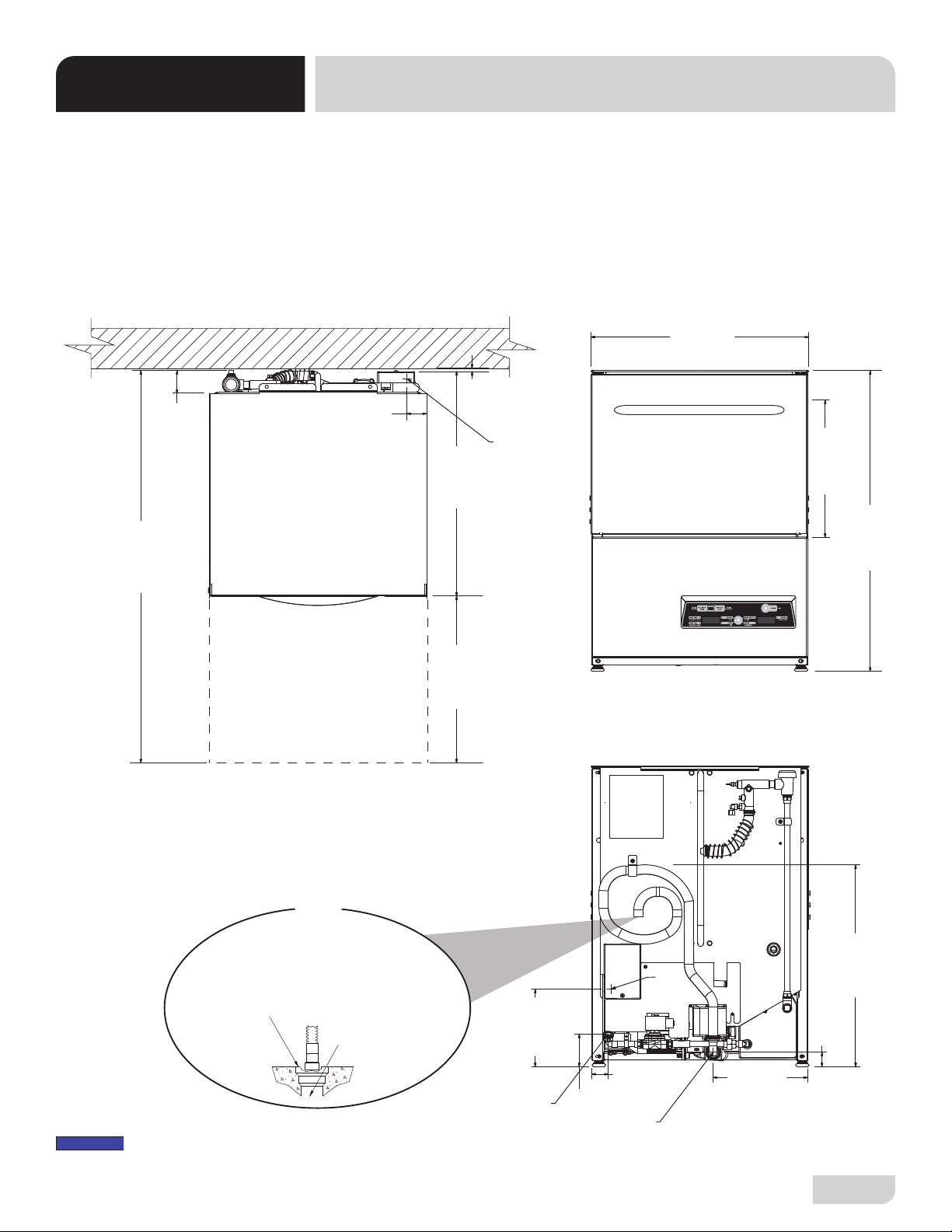
Machine Dimensions ........................................................................................................................ 2
Operating Parameters ...................................................................................................................... 3
Electrical Requirements ................................................................................................................... 4
INSTALLATION
Installation Instructions..................................................................................................................... 5
Inspection......................................................................................................................... 5
Unpacking........................................................................................................................ 5
Plumbing.......................................................................................................................... 5
Water Supply Connections .............................................................................................. 5
Pressure Regulator.......................................................................................................... 6
Shock Absorber ............................................................................................................... 6
Connecting the Drain Line ............................................................................................... 6
Plumbing Check............................................................................................................... 6
Electrical Power Connections .......................................................................................... 7
Voltage Check.................................................................................................................. 7
Surrounding Area............................................................................................................. 7
Thermostats..................................................................................................................... 7
Chemical Feeder Equipment ........................................................................................... 8
Preparing Chemical Feeder Pumps................................................................................. 8
Priming Chemical Feeder Pumps .................................................................................... 8
Programming Chemical Feeder Pumps (UL30)............................................................... 9
Leveling.......................................................................................................................... 12
Initial Fill (UH30-FND Only) ........................................................................................... 12
OPERATION
Operating Instructions .................................................................................................................... 13
Preparation .................................................................................................................... 13
Filling the Wash Tub ...................................................................................................... 13
Ware Preparation........................................................................................................... 14
Washing a Rack of Ware ............................................................................................... 14
Operational Inspection................................................................................................... 14
Shutdown & Cleaning .................................................................................................... 15
Deliming UH30-FND ...................................................................................................... 17
Deliming UL30 ............................................................................................................... 18
Detergent Control........................................................................................................... 19

iv
MAINTENANCE
Preventative Maintenance.............................................................................................................. 20
TROUBLESHOOTING
UH30-FND Setpoints...................................................................................................................... 21
UH30-FND Fault Codes ................................................................................................................. 25
Troubleshooting.............................................................................................................................. 28
PARTS
UH30-FND Control Panel............................................................................................................... 30
UL30 Control Panel ........................................................................................................................ 32
UH30-FND Display Panel............................................................................................................... 33
UL30 Display Panel........................................................................................................................ 34
Terminal Block Box......................................................................................................................... 35
UH30-FND Chemical Feeder Pumps ............................................................................................. 36
UL30 Chemical Feeder Pump Assembly........................................................................................ 37
UL30 Chemical Feeder Pumps ...................................................................................................... 38
UH30-FND Plumbing...................................................................................................................... 39
UL30 Plumbing............................................................................................................................... 41
Plumbing Options ........................................................................................................................... 43
Vacuum Breaker ............................................................................................................................ 44
Wash Manifold................................................................................................................................ 45
Motor & Pump ................................................................................................................................ 47
Rinse Arms & Wash Arms .............................................................................................................. 49
UH30-FND Rinse Tank ................................................................................................................... 51
UH30-FND Door............................................................................................................................. 52
UL30 Door ...................................................................................................................................... 54
Miscellaneous Door Components .................................................................................................. 56
Frame & Panel Components .......................................................................................................... 58
Miscellaneous Parts ....................................................................................................................... 60
Stands & Components ................................................................................................................... 61
UL30 Heater Components.............................................................................................................. 62
UL30 Vacuum Switch ..................................................................................................................... 63
UL30 Vacuum Switch Install........................................................................................................... 64
SCHEMATICS
UH30-FND 208-240 V, 50/60 Hz, 1/3 Phase ................................................................................. 65
UL30 115 V, 50/60 Hz, 1 Phase ..................................................................................................... 66
TABLE OF CONTENTS

07610-004-37-37-P 1
GUIDES GUIDES
SYMBOLS
ABBREVIATIONS & ACRONYMS
!
CAUTION
!
WARNING
NOTICE
- Risk of Injury to Personnel
- Risk of Damage to Equipment
- Risk of Electrical Shock
- Lockout Electrical Power
- Reference Data Plate
- Important Note
i
- Caustic Chemicals
- Instructions Hyperlink
ANSI - American National Standards Institute
Btu/Hr - British Thermal Units per Hour
CFM - Cubic Feet per Minute
GHT - Garden Hose Thread
GPH - Gallons per Hour
GPM - Gallons per Minute
GPG - Grains per Gallon
HP - Horsepower
Hz - Hertz
ID - Inside Diameter
kW - Kilowatts
MCA - Minimum Circuit Ampacity
MOP - Maximum Overcurrent Protection
NFPA - National Fire Protection Association
NPT - National Pipe Thread
OD - Outside Diameter
PRV - Pressure Regulating Valve
PSI -Pounds per Square Inch
V- Volts

2
07610-004-37-37-P
SPECIFICATIONS MACHINE DIMENSIONS
1 5/8
[41 mm]
24 1/4
[615 mm]
14 1/4
[362 mm]
CLEARANCE
33 5/16
[846 mm]
10 1/2
[267 mm]
1 7/8
[48 mm]
8 5/8
[220 mm]
3 5/8
[92 mm]
2 3/4
[70 mm]
1/4
[7 mm]
25
[635 mm]
16 3/4
[426 mm]
DOOR OPEN
41 3/4
[1061 mm]
A
BC
BACK
FRONT
TOP
LEGEND
A - Electrical Connection
B - Water Inlet (with 6' Hose)
(3/4" Male GHT, connect to true
1/2" ID line, MIN 110 °F)
C - Drain Hose
(1" ID, install into 1 1/2" MIN Drain with Air-gap)
C
2 1/8
[54 mm] A
Install Machine
Drain Hose into
1 1/2 [38 mm]
MIN Floor Drain
or Sink
Do NOT install
Drain Hose to
“bottom” of Floor
Drain or Sink.
This can cause
splashback.
All dimensions from the floor can be increased 1”
using the machine’s adjustable feet.
≤ 24
[610 mm]
NOTICE
UH30-FND shown.

07610-004-37-37-P 3
Operating Capacity: UH30-FND UL30
Racks per Hour 24 24
Dishes per Hour 600 600
Glasses per Hour 864 864
Gallons per Rack 1.1 1.2
Gallons per Hour 26.4 28.8
Tank Capacity (Gallons):
Wash Tank 1.1 1.2
Rinse Tank 3.0 N/A
Electrical Loads (as applicable):
Wash Motor HP 1.0 1.0
Rinse Heater kW 6.7 (208 V)/8.2 (230 V) N/A
Wash Heater kW N/A 1.5
Always refer to the machine data plate for specic electrical and water
requirements. The material provided on this page is for reference only and is
subject to change without notice.
HOT WATER SANITIZING
Water Temperatures (°F):
Minimum Wash Temperature 150 N/A
Minimum Rinse Temperature 180 N/A
Minimum Incoming Water Temperature 110 N/A
CHEMICAL SANITIZING
Water Temperatures (°F):
Minimum Wash Temperature N/A 120
Minimum Rinse Temperature N/A 120
Minimum Incoming Water Temperature N/A 120
Other Water Requirements:
Water Flow Pressure (PSI) 20 ± 5 20 ± 5
Flow Rate Minimum (GPM) 6.6 6.6
Water Line Connection Size (NPT) 3/4" GHT 3/4" GHT
Water Line Size (NPT) 1/2" 1/2"
Drain Line Size (NPT) 1" ID 1" ID
Install drain line into MIN 1 1/2" Drain with Air-gap.
Minimum Chlorine Required (PPM) N/A 50
OPERATING PARAMETERS
SPECIFICATIONS
NOTICE
i
NOTICE

4
07610-004-37-37-P
All electrical ratings provided in this manual are for reference
only. Always refer to the machine data plate to get exact electrical
information for this machine. All electrical work performed on
machines should be done in accordance with applicable
local, state, territorial, and national codes. Work should only
be performed by qualied electricians and authorized service
agents.
The electrical congurations of this series of machines are as
follows:
Available Electrical Characteristics:
UH30-FND
• 208 V, 60 Hz, Single-phase
• 230 V, 60 Hz, Single-phase
UL30
• 115 V, 60 Hz, Single-phase
Available Wash Tank Heater:
• 1.5 kW (UL30 Only)
*Motor and heater do not operate at same time. Total load based
on motor load.
VOLTS 208 230
PHASE 1 1
FREQ 60 60
WASH
MOTOR
AMPS
5.0 A 5.0 A
RINSE
HEATER
AMPS
32.2 A 35.7 A
TOTAL
LOAD 37.2 A 40.7 A
NOTICE
i
ELECTRICAL REQUIREMENTS
SPECIFICATIONS
UH30-FND
UL30
VOLTS 115
PHASE 1
FREQ 60
WASH
MOTOR
AMPS
10.0 A
WASH
HEATER
AMPS
13.0 A
TOTAL
LOAD 10.0 A*
Electrical Characteristics

07610-004-37-37-P 5
Before installing the unit, check packaging and machine for damage. Damaged
packaging might be an indication of damage to the machine. If there is any type
of damage to both packaging and unit, do not throw away the packaging. The
dishmachine has been inspected at the factory before shipping and is expected
to arrive in new, undamaged condition. However, rough handling by carriers or
others might result in damage to the unit while in transit. If this occurs, do not return
the unit to the manufacturer. Instead, contact the carrier and ask them to send a
representative to the site to inspect the damage and request that an inspection
report be completed.
Contact the carrier within 48 hours of receiving the machine as well as the dealer
that sold you the unit.
Remove the box and machine from the pallet before installing. Open the front
door and remove all of the materials from inside. Once unpacked, verify there are
no missing parts (reference the Parts section). If a part is missing, contact the
manufacturer immediately.
All plumbing connections must be made to adhere to local, state, territorial, and
national codes. The installing plumber is responsible for ensuring the incoming
water lines are ushed of debris before connecting to the machine. Note that chips
and materials from cutting processes can become lodged in the solenoid valves
and prevent them from opening or closing. Any valves that are found to be fouled
or defective because of foreign matter left in the water line, and any subsequent
damage, are not the responsibility of the manufacturer.
A water hardness test must be performed. A hardness test kit can be found on the
warning tag that is attached to the incoming plumbing connection on the back of the
machine. If water hardness is higher than 3 GPG, install a water softener or install
the optional Scale Prevention System (SPS). See the Plumbing Options page and
the next section for more information on the SPS.
See the Machine Dimensions page and reference item "B" for water inlet connection
location.
The manufacturer does NOT endorse "Tankless On-demand" water heaters
for use with their dishmachines. The manufacturer DOES endorse, and highly
recommends, the standard "Tank" style water heaters, sized to properly handle the
water heating requirements of the facility.
INSTRUCTIONS
INSTALLATION
INSPECTION
Do not throw away
container if damage is
evident!
UNPACKING
PLUMBING
A water hardness test
must be performed.
The plumber must ush
the incoming water line!
NOTICE

6
07610-004-37-37-P
PRESSURE
REGULATOR
SHOCK ABSORBER
CONNECTING THE
DRAIN LINE
A water hardness test must be performed. If water hardness is higher than 3 GPG
and a water softener is not being used, install an SPS (see Plumbing Options
page) into the water line between the facility water line and the machine water line
(installed at the factory). Observe proper inlet/outlet water directions. A water shut-
o valve should be installed before installing the SPS to allow access for service.
The water supply must be capable of a minimum of 20 ± 5 PSI “ow” pressure at
the recommended temperature indicated on the data plate.
If water hardness tests at 3 GPG or lower, connect the machine water line (installed
at the factory) to the facility water line. A water shut-o valve should be installed
in the water line between the facility supply and the machine to allow access for
service. The water supply line must be capable of a minimum of 20 ± 5 PSI “ow”
pressure at the recommended temperature indicated on the data plate.
The manufacturer has an optional water pressure regulator to accommodate areas
where water pressure uctuates or is higher than the recommended pressure. Take
care not to confuse static pressure with ow pressure: static pressure is line pressure
in a “no ow” condition (all valves and services are closed); ow pressure is the
pressure in the ll line when the valve is opened during the cycle. See the Plumbing
Options page.
It is suggested that a shock absorber (not supplied) be installed on the incoming
water line. This prevents water hammer (hydraulic shock)—induced by the solenoid
valve as it operates—from causing damage to the equipment. See the Plumbing
Options page.
The dishmachine has a pumped (pressure) drain capable of pumping waste water
to a height of 24” above the oor to the kitchen’s drain system. Each dishmachine
is supplied with a drain hose. When installed, it will extend from the rear side of the
machine. There must be an air-gap between the machine drain line and the oor
sink or drain. If a grease trap is required by code, it should have a ow capacity of
12 GPM.
After installing the incoming ll line and the drain line, slowly turn on the water sup-
ply to the machine. Check for any leaks and repair as required. All leaks must be
repaired before operating the machine.
Take care not to confuse
static pressure with
ow pressure!
PLUMBING CHECK
INSTRUCTIONS
INSTALLATION
WATER SUPPLY
CONNECTIONS:
WATER HARDNESS
HIGHER THAN 3 GPG
WATER SUPPLY
CONNECTIONS:
WATER HARDNESS
LOWER THAN 3 GPG
Shut-off
Valve
Adapter AdapterSPS Machine
Water Line
Facility
Water Line
*Adapters needed will vary.
Example

07610-004-37-37-P 7
Electrical and grounding conductors must comply with the applicable portions of the
National Electric Code ANSI/NFPA 70 (latest edition) and/or other electrical codes.
The data plate is located at the left-front side of the dishmachine. Refer to the data
plate for machine operating requirements, machine voltage, total amperage, and serial
number.
Remove the back panel and set aside. This will require removing the screw at the
bottom of the back panel with a phillips screwdriver. Install 3/4” conduit into the pre-
punched holes in the back of the control box. Route power wires and connect to power
block and grounding lug. Install the service wires (L1 and L2 for UH30-FND, L1 and
N for UL30) to the appropriate terminals as they are marked on the terminal block.
Install the grounding wire into the lug provided. It is recommended that “DE-OX” or
another similar anti-oxidation agent be used on all power connections.
UH30-FND UL30
Ensure the ON/OFF switch is in the OFF position and apply power to dishmachine.
Check the incoming power at the terminal block and ensure it corresponds with the
voltage listed on the data plate. If not, contact a qualied service agency to examine
the problem. Do not run dishmachine if voltage is too high or too low. Shut-o the
service breaker and advise all proper personnel of the location of the breaker and
any problems. Replace the control box cover and tighten-down the screws.
This is a commercial dishmachine and reaches temperatures that can exceed
those generated by a residential machine. Surrounding countertops, cabinets, ooring
material, and suboor material must be designed and/or selected with these higher
temperatures in mind.
Any damage to surrounding area that is caused by heat and/or moisture to materials
that are not recommended for higher temperatures will not be covered under warranty
or by the manufacturer.
The thermostats on this dishmachine have been set at the factory. They should only
be adjusted by an authorized service agent.
INSTRUCTIONS
INSTALLATION
ELECTRICAL POWER
CONNECTIONS
Disconnect electrical
power at the breaker or
disconnect switch and
tag-out in accordance with
procedures and codes.
THERMOSTATS
SURROUNDING
AREA
VOLTAGE CHECK
NOTICE
i
L1 L2 GRND L1 N GRND

8
07610-004-37-37-P
CAUTION! Chlorine-based sanitizers can be detrimental to this machine
if the chemical solution is too strong. See a chemical professional to
ensure the dispenser is set-up correctly.
The bottom of the chemical container cannot be located any higher than 8” from the
oor. If the unit is equipped with the 6” or 18” table stand, the highest position will be
14” or 26” from the oor, respectively. It is important to remember that if you decide
to operate the unit in chemical-sanitizing mode, you must ensure an appropriate
chlorine-based sanitizer is used in the nal rinse line.
The UH30-FND dishmachine is supplied with detergent and rinse-aid chemical
feeder pumps.
The UL30 dishmachine is supplied with detergent, rinse-aid, and sanitizer chemical
feeder pumps.
Locate the open ends of the chemical tubes with the tube stieners and place each
one in the appropriate container.
• Red Tubing = Detergent • Blue Tubing = Rinse-Aid
• White Tubing = Sanitizer
Chemical feeder pumps need priming when the machine is rst installed or if the
chemical lines have been removed and air was allowed to enter.
CAUTION! Water must be in the sump and wash tank before chemicals
are dispensed.
UH30-FND
1. Press and hold prime button toward DETERGENT PRIME until display shows
timer. Priming cycle defaults to 70 seconds. Observe wash tank during priming
cycle. If too much detergent, press prime button to stop priming cycle. If not
enough, run priming cycle again.
2. Press and hold prime button toward RINSE AID PRIME until display shows
timer. Priming cycle defaults to 180 seconds.
CHEMICAL FEEDER
EQUIPMENT
PRIMING CHEMICAL
FEEDER PUMPS
WARNING! Some of the
chemicals used in
dishwashing might cause
chemical burns if they
come in contact with skin.
Wear protective gear when
handling these chemicals.
If any contact with skin
occurs, immediately
follow the treatment
instructions provided
with the chemicals.
PREPARING
CHEMICAL FEEDER
PUMPS
!
CAUTION
!
WARNING
!
CAUTION
INSTRUCTIONS
INSTALLATION
180
70

07610-004-37-37-P 9
3. The amount of detergent might need adjustment depending on water quality and
type of detergent. The amount of rinse-aid might need adjustment depending
on water hardness and results. Refer to UH30-FND Setpoints section for
instructions on adjusting amount of chemicals being dispensed.
UL30
4. Hold each prime switch (Detergent, Rinse-aid, and Sanitizer) until the respective
chemical can be seen entering the wash tank.
5. Detergent is dispensed as required during the wash cycle by the timer. The
amount of detergent might need to be increased or decreased depending upon
water quality and type of detergent.
6. Rinse-aid is dispensed as required into the nal rinse. The amount of rinse-aid
might need to be adjusted depending upon water hardness and results.
7. Sanitizer is dispensed proportionally into the nal rinse water line. The amount
of sanitizer might need to be adjusted depending on concentration.
8. See Programming Chemical Feeder Pumps (UL30) section to adjust chemical
amounts using the universal timer.
INSTRUCTIONS
INSTALLATION
PRIMING CHEMICAL
FEEDER PUMPS
PROGRAMMING
CHEMICAL FEEDER
PUMPS (UL30)
To access programming mode, machine must be ON and between cycles.
The PROGRAM (PGM) light will be ashing.
1. Locate universal timer. On the timer, locate programming board and
programming buttons.
8 7 6 5 4 3 2 1
ON
C
H
E
C
K
F
U
S
E
Universal timer is
located on control panel.
Use Parts section of this
manual for reference.
UL30 DIP-switch Settings
(0 = On, X = O)
←
ON
X X X X
0 0 0 0
8 7 6 5 4 3 2 1

10
07610-004-37-37-P
INSTRUCTIONS
INSTALLATION
2. Programming board and buttons are not labeled on the timer. Use the graphic
below for reference.
3. Press and hold both the MOVE and ENTER buttons simultaneously for two
seconds then release. PGM light will go steady and light A will start ashing.
4. Press MOVE button to move the ashing light to E, F, G, or H. Options A–D are
not adjustable.
PROGRAMMING
CHEMICAL FEEDER
PUMPS (UL30)
PGM UL30
E Rinse-aid
F Fill
G Sanitizer
H Detergent
1 2 3 4 5 6 7 8
ON
8
4
2
1
0.8
0.4
0.2
0.1
A
B
C
D
E
F
G
H
PGM
ACCEPT
MOVE
ENTER
IN
SEC
LIGHTS TIME
BUTTONS
C
H
E
C
K
F
U
S
E
1 2 3 4 5 6 7 8
ON
8
4
2
1
0.8
0.4
0.2
0.1
A
B
C
D
E
F
G
H
PGM
ACCEPT
MOVE
ENTER
IN
SEC
LIGHTS TIME
BUTTONS
C
H
E
C
K
F
U
S
E
= Light Steady
= Light Flashing
1 2 3 4 5 6 7 8
ON
8
4
2
1
0.8
0.4
0.2
0.1
A
B
C
D
E
F
G
H
PGM
ACCEPT
MOVE
ENTER
IN
SEC
LIGHTS TIME
BUTTONS
C
H
E
C
K
F
U
S
E
Example here shows
option G (sanitizer)
being selected.

07610-004-37-37-P 11
5. Press ENTER button. PGM light will stay steady, lights for the current time
setting will come on, and ACCEPT light will start ashing.
6. Press MOVE button to cycle through the dierent time options. To choose a time
option, press ENTER while the light is ashing on that option. To deselect the
option, press ENTER again.
7. Once all desired time options are selected, press MOVE button until ACCEPT
light is ashing (lights for selected time options should still be steady).
1 2 3 4 5 6 7 8
ON
8
4
2
1
0.8
0.4
0.2
0.1
A
B
C
D
E
F
G
H
PGM
ACCEPT
MOVE
ENTER
IN
SEC
LIGHTS TIME
BUTTONS
C
H
E
C
K
F
U
S
E
= Light Steady
= Light Flashing
Example here shows
current setting for G
at 9.2 seconds (each
selected time option
is added to get the
total).
1 2 3 4 5 6 7 8
ON
8
4
2
1
0.8
0.4
0.2
0.1
A
B
C
D
E
F
G
H
PGM
ACCEPT
MOVE
ENTER
IN
SEC
LIGHTS TIME
BUTTONS
C
H
E
C
K
F
U
S
E
Example here shows
setting for G changed
to 6.5 seconds (each
selected time option
is added to get the
total).
CAUTION! Light for each
desired option must be
steady before moving on.
!
CAUTION
INSTRUCTIONS
INSTALLATION
1 2 3 4 5 6 7 8
ON
8
4
2
1
0.8
0.4
0.2
0.1
A
B
C
D
E
F
G
H
PGM
ACCEPT
MOVE
ENTER
IN
SEC
LIGHTS TIME
BUTTONS
C
H
E
C
K
F
U
S
E
= Light Steady
= Light Flashing
PROGRAMMING
CHEMICAL FEEDER
PUMPS (UL30)

12
07610-004-37-37-P
INSTRUCTIONS
INSTALLATION
8. Press ENTER button. This saves the changed parameters and exits the
programming mode. PGM light will go from steady to ashing.
9. To change any other values, repeat the process above. To revert back to a
previous setting, repeat the process above and change parameters back to
previous settings.
In programming mode, if there have been no keypad inputs for approximately two
minutes, the system will automatically exit out of programming mode. Any changes
to parameters will be lost when programming mode is automatically exited.
The dishmachine is designed to operate while level. This is important to prevent any
damage to the machine during operation and to ensure the best possible results.
The unit comes equipped with adjustable bullet feet which can be turned using a
pair of pliers. Since this machine is an undercounter unit, it should be leveled as
close as possible to the unit's location before it is pushed under the counter.
1. Press POWER button and listen for machine to stop lling.
2. Press POWER button and listen for machine to stop draining.
3. Repeat Steps 1 and 2.
4. Press POWER button and listen for machine to stop lling.
5. Machine is now ready for operation.
1 2 3 4 5 6 7 8
ON
8
4
2
1
0.8
0.4
0.2
0.1
A
B
C
D
E
F
G
H
PGM
ACCEPT
MOVE
ENTER
IN
SEC
LIGHTS TIME
BUTTONS
C
H
E
C
K
F
U
S
E
PROGRAMMING
CHEMICAL FEEDER
PUMPS (UL30)
LEVELING
x2
180
180
180
INITIAL FILL
(UH30-FND ONLY)
UH30-FND models with
serial numbers before
23D415452 have dierent
initial ll instructions.
Click here to open earlier
manual.

07610-004-37-37-P 13
Before operating machine, verify:
1. Strainer is in place and clean.
2. Wash and rinse arms are screwed securely into place and end-caps are tight.
3. Wash and rinse arms rotate freely.
4. Chemical levels in chemical containers are correct.
1. Close door.
2. Turn machine on.
3. Machine will automatically begin to fill.
4. Once wash tub is filled, wait until wash temperature is at least 150 °F for UH30-
FND and 120 °F for UL30 before operating machine.
OPERATING INSTRUCTIONS
OPERATION
PREPARATION
FILLING THE
WASH TUB
180
UH30-FND UL30
See Initial Fill section
for UH30-FND models.
UL30 has combined wash/
rinse arms.

14
07610-004-37-37-P
Properly preparing ware will help ensure good results and fewer re-washes. If not
done properly, ware might not come out clean and the eciency of the machine will
be reduced. Putting unscraped dishes into the machine aects its performance, so
alwasys remove scraps from ware before loading into a rack. Pre-rinsing and pre-
soaking are good ideas, especially for silverware and casserole dishes.
Place cups and glasses upside-down in racks so they don't hold water during
the cycle. The dishmachine sanitizes as well as cleans. To do this, ware must be
properly prepared before being placed in the machine.
UH30-FND
1. Ensure machine is on and at operating temperature.
2. Open door and load rack.
3. Push START button.
4. LED will turn green. Operator has three seconds to close door before LED goes
out and START button must be pressed again.
5. Cycle automatically starts when door is closed.
UL30
1. Ensure machine is on and at operating temperature.
2. Open door and load rack.
3. Close door and ensure WASH/DELIME switch is on WASH.
4. Push START button. Cycle light comes on and cycle automatically starts.
Based on use, the strainer might become clogged with soil and debris as the
workday progresses. Operators should regularly inspect the strainer to ensure it has
not become clogged. If clogged, it will reduce the washing capability of the machine.
Instruct operators to clean out the strainer at regular intervals or as required by
workload.
WASHING A RACK
OF WARE
WARE
PREPARATION
OPERATIONAL
INSPECTION
OPERATING INSTRUCTIONS
OPERATION

07610-004-37-37-P 15
OPERATING INSTRUCTIONS
OPERATION
1. At end of workday, close door. UH30-FND: Press POWER button. UL30: Flip ON/
OFF switch to OFF position.
2. Drain pump will activate and empty machine of water.
3. When draining stops, remove strainer.
4. Remove soil and debris from strainer and set aside.
5. Unscrew wash and rinse arms manifolds. Remove end-caps and ush arms with
water. Use a brush to clean inside of the arms. If nozzles appear to be clogged, use
a toothpick to remove debris.
SHUTDOWN &
CLEANING
End-cap
Nozzle
180
UH30-FND UL30
CAUTION! Do NOT beat
strainers to remove
soil and debris!
!
CAUTION
UL30 has combined wash/
rinse arms.
This manual suits for next models
1
Table of contents
Other Wareforce Dishwasher manuals
Popular Dishwasher manuals by other brands

V-ZUG
V-ZUG Adorina V400 INFORMATION FOR USE

Moyerdiebel
Moyerdiebel 201HT M4 Series Installation & operation manual

Moyerdiebel
Moyerdiebel 351HT Installation & operation manual

Moyerdiebel
Moyerdiebel DF-M6 Technical manual

New Air
New Air ADW-2600W instruction manual

Moyerdiebel
Moyerdiebel MH-60M5 Technical manual