WAREMA GA Standard User manual

1
warema_866217_alhb_en_v6•2022-07-01 We reserve the right to make technical modifications
General information
Fig. 1 Floor distribution control Standard (GA) Standard for
four facades
A power supply unit for supplying the control voltage of the
downstream motor control unit is integrated in the GA unit.
The GA unit can be used to operate the motor control units
of up to 4 facades either via a higher-level central control
or facade-by-facade on a floor through floor switches.
Commands of the central control take precedence over
the local floor switches and are passed on directly to the
motor control units. The local floor switches are blocked by
a central command.
Intended use
The Floor distribution control Standard (GA) Standard was
developed to control sun shading systems. The approval of
the manufacturer must be obtained for uses outside of the
purposes listed in these instructions.
Safety instructions
WARNING
The electrical installation (assembly)/dis-
mantling must be performed by a certified
electrician in accordance with the electri-
cal installation regulations published by
the Association of German Electrical Engi-
neers (VDE 0100) or the standards and reg-
ulations of the country in which the device
is being installed. The electrician must ob-
serve the installation instructions included
with the supplied electrical devices.
WARNING
If hazard-free operation cannot be as-
sumed, the device may not be started or
must be deactivated. This assumption is
justified if:
the housing or the connecting lines show
signs of damage,
the device is no longer working.
WARNING
It is important to comply with the following
points in the interest of personal safety.
■Make sure that no persons or objects are located in the
path of any driven parts (blinds, roller shutters, etc.)!
■Disconnect the MSE from the operating voltage if cleaning
or other maintenance work must be performed!
Electrical connection
An on-site overload current protection device (fuse) and a
disconnecting and isolating switch to switch off the entire
system must be provided.
Operating and installation instructions
GA Standard for 4 facades
Valid from
1. February 2022
Keep for future use..

warema_866217_alhb_en_v6•2022-07-01We reserve the right to make technical modifications
2
Function
Momentary-contact switches or latched switches can be
used as floor operating elements. The move commands
of the floor switches are passed on directly to the motor
control units.
The operating elements may not be jumpered.
For the use of momentary contact switches as floor
switches this means:
The operator has to press the floor momentary-contact
switch until the sunblinds of the controlled facade have
reached the desired position.
A move command from a higher-level central control
takes precedence over the floor momentary-contact
switch.
For the use of latched switches as floor switches this
means:
The operator presses the floor latched switch and
moves away from the operating point. The sunblinds
move UP or DOWN to the end position.
A move command from a higher-level central control
takes precedence over the floor latched switch. The
sunblinds move in the direction specified by the central
control exactly as long as the central command remains
active. Afterwards the sunblinds move again into the
end position specified by the latched floor switch.
When the floor latched switches are latched, the local
switches of the motor control unit are blocked
Commissioning
The device is ready for operation after the installation has
been completed and the operating voltage applied.
Maintenance
There are no parts within the device that require mainte-
nance. In the event of a malfunction, the installed miniature
fuse may only be exchanged by a certified electrician.
Cleaning
Clean the housing with a soft, dry cloth. Do not use deter-
gents, cleaning agents, solvents, abrasive substances or
steam cleaners!
Liability
Failure to comply with the product information contained in
these instructions and any use of the device other than its
intended use and purpose may result in the manufacturer
refusing to honour warranty claims for product damage. In
this case, liability for consequential damage to persons or
property will also be excluded. Also observe the informa-
tion in the operating instructions for your sun shading
system. The automatic or manual operation of the sun
shading system when iced over as well as using the sun
shading system during severe weather may cause dam-
age and must be prevented by the user through suitable
precautions.
Obligations for the disposal of electrical devices
A marking with this symbol indicates the following
obligations under the scope of legal regulations:
The owner of this electrical device must dispose of it
separately from unsorted municipal waste for further
recycling.
Used batteries and accumulators that are not enclosed
in the old device, as well as lamps/bulbs that can be
removed from the old device without breaking, must be
disposed of separately.
Distributors of electrical devices and disposal companies
are obliged to take back the equipment free of charge
.
The owner must take it upon themselves to delete any
personal data contained in the electrical device prior to
disposal.
Technical data
GA Standard min. typ. max. Unit
Supply 230 V AC
operating voltage 207 230 253 V AC
power consumption 5 80 VA
Output
Control voltage 22 29 32 V DC
Current
(all 4 facades)
2 A
Input (central / local)
Input voltage inactive 0 0 2 V DC
Input voltage active 17 24 32 V DC
Input current active 13 mA
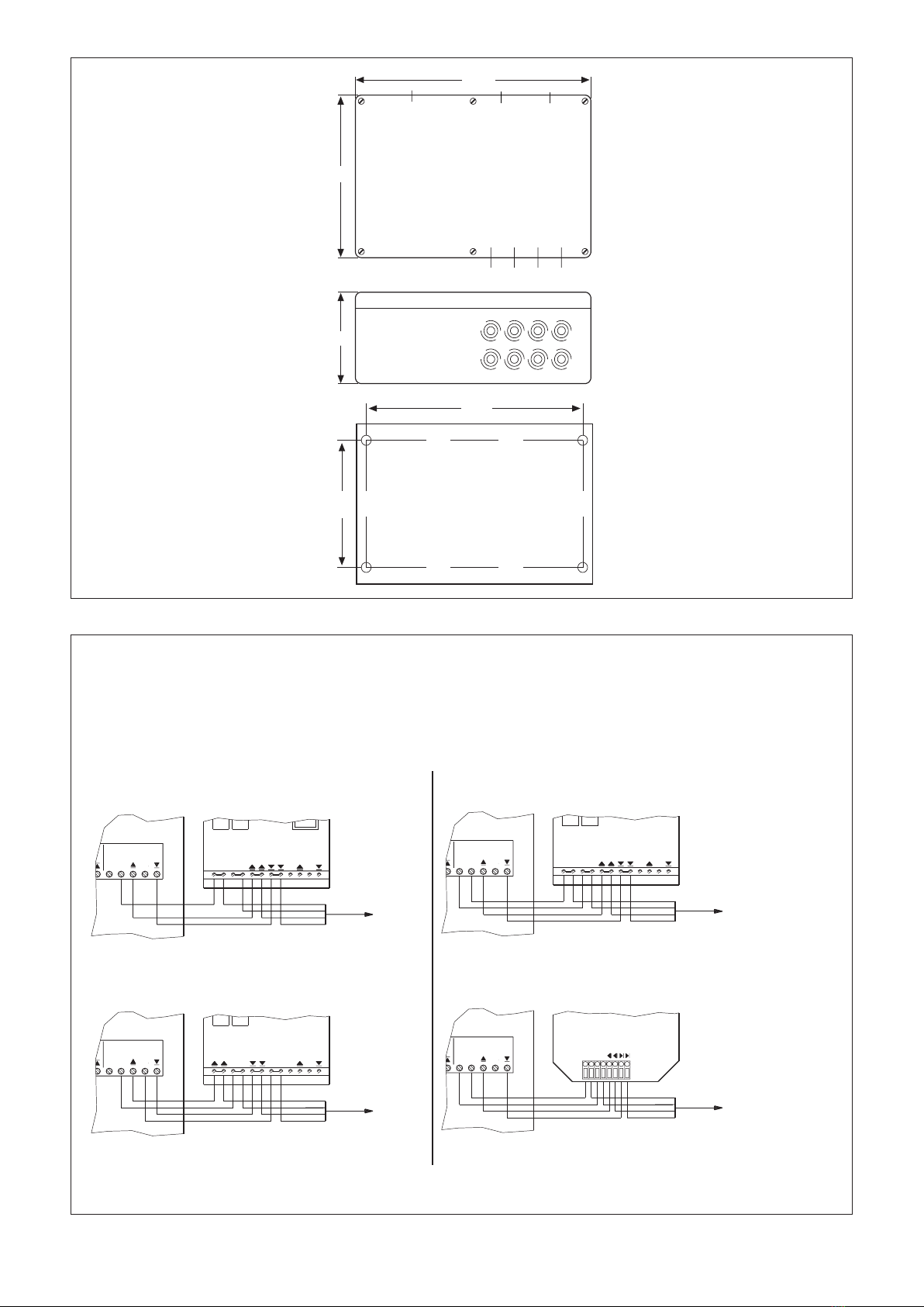
Housing
Dimensions L x W x H
240 x 160 x 90 mm
degree of protection IP 54
Connection
All connections screw terminals
Connection terminals
supply line 0,5...1,5 mm2
control line,
push button line
0,5...1,5 mm2
Miscellaneous
Conformity
can be viewed at
www.warema.de/ce
This device complies with the EMC directives for use in re-
sidential and commercial areas.
Ambient conditions
Operating temperature 0 40 °C
Storage temperature -25 75 °C
Humidity
(not condensing)
10 40 80 %Hrel
Degree of soiling 2
Article number
Floor distribution control
Standard (GA) Standard
for 4 facades
1002 253
WAREMA Renkhoff SE
Hans-Wilhelm-Renkhhoff-Strasse 2
97828 Marktheidenfeld, Germany

3
warema_866217_alhb_en_v6•2022-07-01 We reserve the right to make technical modifications
240
160
M25 M25M20
8 pcs. Plug (step support) M20
90
228.5
130.5
Mounting holes Ø 4 mm
Fig. 2 Dimensional drawing
control
Facade 2
E
12
0
P
P
UP
DOWN
+24V
(2Res.)
Control line
00++
Central control
YR 6x0.8mmø
0V
Kompakt
MSE
Standard
MSE
0E0 E
P
(2Res.)
YR 6x0.8mmø
Control line
Central control
AS4
MSE
0+0 +
P
UP
(2Res.)
DOWN
YR 6x0.8mmø
±0V
+24V
Control line
Central control
DOWN
single
UP
0V
13 14 15 16
Facade 3
control
P
0
12 13 14
E
1615
12
P
Facade 4
14 161513
0
E
control
0
+
+
0
DOWN
+24V
UP
±0V
Central control
Control line
(2Res.)
YR 6x0.8mmø
Piccolo M230
MSE
14
control
P
0
12 13
E
Facade 1
15 16
The maximum current carrying capacity of the floor control distribution board amounts to 2 A. The following current values have to be taken into consideration when calculating the maximum
number of motor control units that can be connected to a floor control distribution board: per MCU Standard
per MCU Piccolo
100 mA has to be deducted at the first floor control distribution board for each further GA unit.
25mA => corresponds to 80 MCUs per floor control distribution board
per MCU Arbeitsstellung
25mA => corresponds to 80 MCUs per floor control distribution board
At a MCU Compact a maximum of 200 MCU may be connected to the floor control distribution board.
The specified number of units has been calculated without consideration of the voltage drop. Please observe the corresponding voltage drop diagrams in this respect.
Fig. 3 Terminal diagram GA to MCU

warema_866217_alhb_en_v6•2022-07-01We reserve the right to make technical modifications
4
E
PP
E
P
E
P
E
= down
E = individual
= up
Control pan.
E
10
10
Control pan.
E
E
10
Control pan.
E
10
Control pan.
Facade 1
24V DC
55 VA
F2A
0
P
Facade 2
16 15 1214 13 11
control
16
E
15
E
1214
0
13 11
P
0 P
control
control
Facade 3
E
16 15 12
0
14 13
P
11
control
Facade 4
E
16 15
0 P
1214 13 11
230V AC
0.315 AT
F1
L1
L1 N
N
X1
PE
PE
987 6354 21
Central contro
9 8 7
E
6
E
3
E
54
0
2
0
1
E 0 0
Central contro
Central contro
98
E
7 6 3
E
54
0 0
21
3X2X X4
Central contro
E
9 8 7 6
E 0 0
354 21
X5
3x1.5mm
2
230V,50Hz,16A
Connecting line
3
YR 14x0,8mmØ
Central control output 24V=
to the next
Floor distribution control
10
Control pan.
E
10
Control pan.
E
10
Control pan.
E
10
E
Control pan.
control
Facade 1
E
16 15 12
0
14 13
P
11
control
Facade 2
E
16 15 12
0
14 13
P
11
control
Facade 3
E
16 15 12
0
14 13
P
11
control
Facade 4
E
16 15 12
0
14 13
P
11
0.315 AT
F1
L1
L1 N
N
Connecting line
X1
PE
PE
3
230V,50Hz,16A
NYM-J 3x1.5mm
2
Central contro
9 8
E
7 6 3
E
54
00
21
Central contro
98
E
7 6 3
E
54
00
21
Central contro
98
E
7 63
E
54
0 0
21
Central contro
98
E
7 6 3
E
54
0 0
21
0 = 0V
X5X4X3X2
E = individual
= up
= down
E = individual
= up
= down
E = individual
= up
= down
21
P
0
E
Channel 1
Floor switch
Attention:
A wire jumper only needs to be inserted
at the first floor distribution board
at one of the facade terminal strips
(-X2 to -X5) between terminal 2(0)
and terminal 13(0) (see example below).
Floating contacts of the central sun shading control
Facade 1 Facade 2 Facade 3 Facade 4 Attention:
If a sun shading control system is not connected
to the floor distribution board, a wire jumper must be
inserted at each of the facade terminal strips(-X2 to -X5)
between terminal 6(E) and terminal 12(P)
Floor distribution control 1
Floor distribution control 2
*
*
Attention:
With the floor distribution
control Standard, the
floor push button inputs must
not can be jumpered.
Fig. 4 wiring diagram
This manual suits for next models
1
Popular Power Supply manuals by other brands

Johansson
Johansson 9933 instruction manual

Keysight
Keysight E3631A Service guide

Cisco
Cisco PWR-7513-DC Replacement instructions

AMI
AMI 4Q06125PS-430 Installation, operation and maintenance instructions

Elektro-Automatik
Elektro-Automatik EA-PS 816-20R User instruction manual

Sony
Sony DC-78 operating instructions

Honeywell
Honeywell 900P01 installation and replacement

Pulsar
Pulsar PSACH 01246 instruction manual

Walrus Audio
Walrus Audio AETOS instruction manual

GRAUPNER
GRAUPNER SWITCHING POWER SUPPLY 5-15V 0-40A manual

Eurolux
Eurolux H187 quick start guide

Phoenix Contact
Phoenix Contact QUINT4-PS/1AC/24DC/20 datasheet