WarmFlow A Series User manual

High Efficiency
Variable Speed
Air Source Heat Pumps
Models covered by this manual:
A-Series
Air Source AS01-R32 AS02-R32 AS03-R32
Incorporating: User Instructions
Installation Instructions
Service Instructions
Guarantee Terms & Conditions

INSTALLATION, COMMISSIONING & SERVICING
This appliance must be installed as described herein and the installation commissioned by
competent persons as instructed. The Installation/Commissioning Certificate supplied with the
product must be completed and returned to the manufacturer with proof of purchase (e.g. receipts
/ invoices).
This appliance must be serviced annually by competent persons, the Service Record completed
on each occasion and proof of servicing (e.g. receipts / invoices) retained.
The complete guarantee policy statement is included in Section 4.
FAILURE TO COMMISSION, REGISTER AND ANNUALLY SERVICE THIS
PRODUCT WILL INVALIDATE ALL GUARANTEES
TECHNICAL, SPARES & GUARANTEE CLAIMS
For technical advice about the installation, commissioning, servicing or use of this appliance,
please contact the Warmflow Customer Care Centre by post, phone, fax or email at the addresses
below. Please also refer to our website.
In the unlikely event that replacement components might be required within the guarantee period,
please notify the Customer Care Centre in writing, by post, fax or email, stating the nature of the
fault and the part number of the replacement components required.
Warmflow Customer Care Centre
Warmflow Engineering
Lissue Industrial Estate
Moira Road
Lisburn
BT28 2RF
Northern Ireland
Telephone
United Kingdom: 028 9262 1515
Republic of Ireland: 048 9262 1515
Facsimile
United Kingdom: 028 9262 0869
Republic of Ireland: 048 9262 0869
Email
Website
www.warmflow.co.uk

Page 1
CONTENTS
Contents ...................................................................................................................................................................... 1
1 USER INSTRUCTIONS ........................................................................................................................................ 3
1.1 Intended Use ................................................................................................................................................................. 3
1.2 Compliances ................................................................................................................................................................. 3
1.3 Basic Operation ............................................................................................................................................................. 3
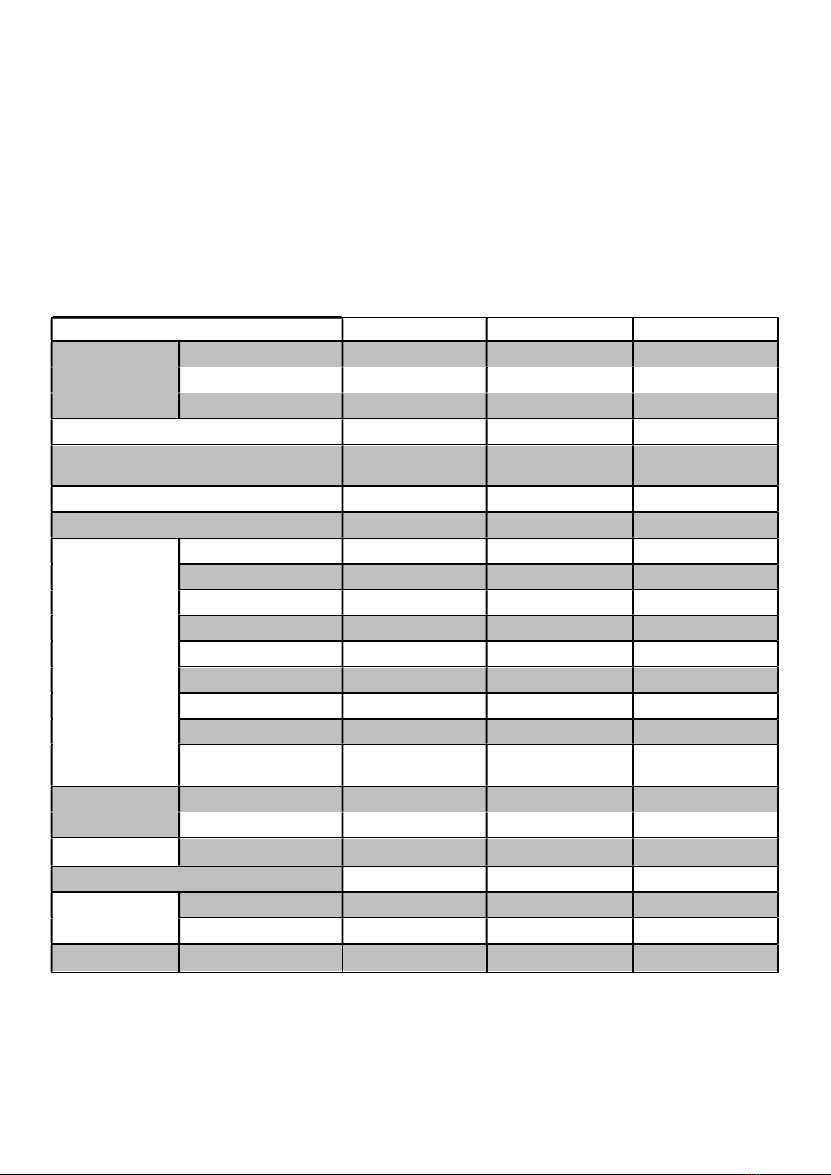
1.4 Product Data ................................................................................................................................................................. 4
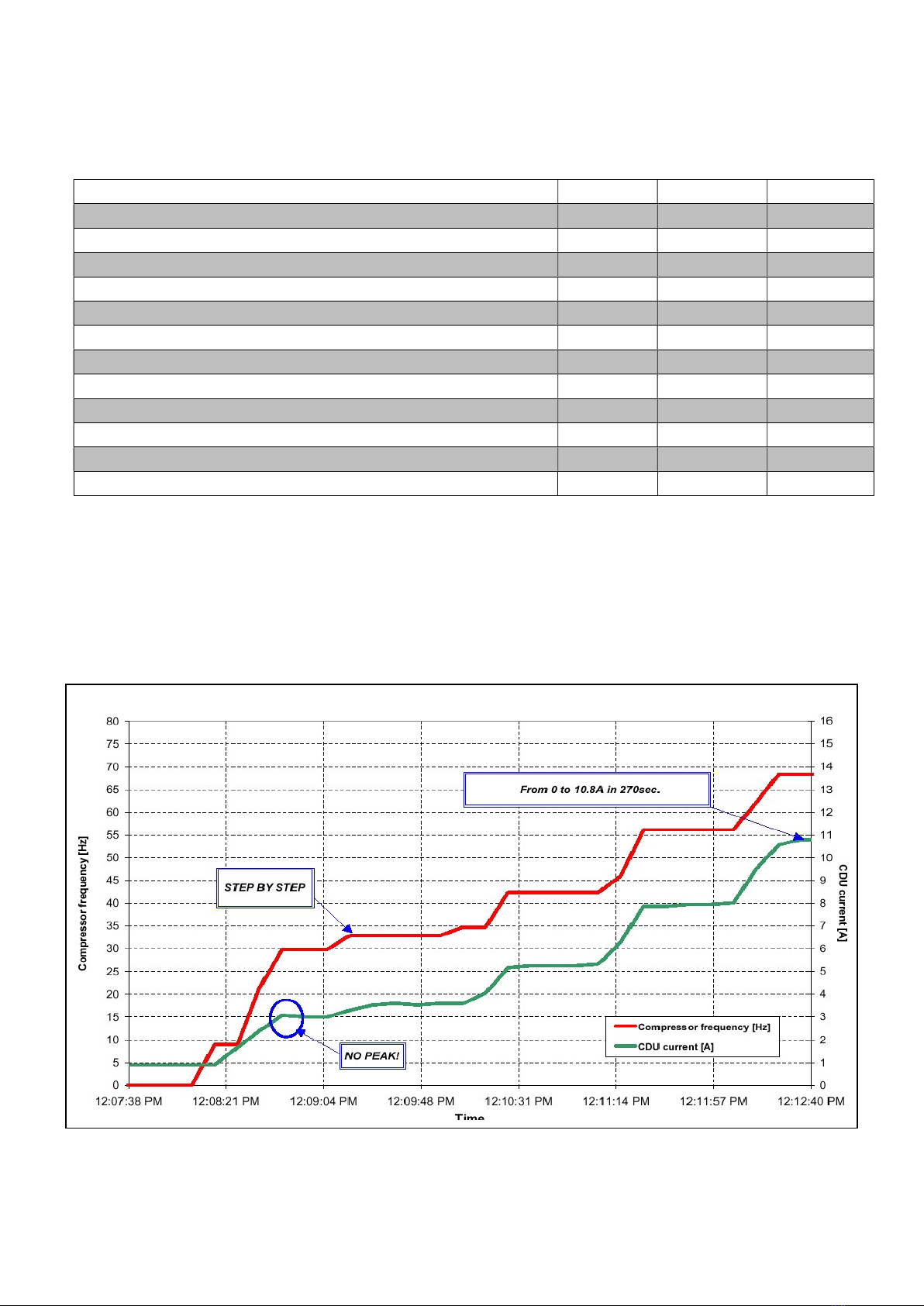
1.4.1 Starting Current ..................................................................................................................................... 6
1.5 Construction .................................................................................................................................................................. 7
1.6 Supplied Components ................................................................................................................................................... 7
1.7 Storage / Transport ....................................................................................................................................................... 8
2 USER INTERFACE .............................................................................................................................................. 9
2.1 Home Screen Icons ....................................................................................................................................................... 9
3 AIR SOURCE HEAT PUMP INSTALLATION ................................................................................................... 33
3.1 General ....................................................................................................................................................................... 33
3.2 Access ......................................................................................................................................................................... 35
3.3 Unpacking ................................................................................................................................................................... 35
3.4 Heating Circuit Connection .......................................................................................................................................... 36
3.4.1 Heating Medium .................................................................................................................................. 36
3.4.2 Heating Connections to the Heat Pump ............................................................................................. 36
3.4.3 Heating Circuit and Integrated Circulator............................................................................................ 36
3.4.4 Bypass / Open Zones ......................................................................................................................... 36
3.4.5 Freeze Protection ................................................................................................................................ 37
3.4.6 Heating Circuit Line Components ....................................................................................................... 37
3.5 Defrosting .................................................................................................................................................................... 39
3.6 Air Vent ....................................................................................................................................................................... 39
3.7 Buffer tank ................................................................................................................................................................... 39
3.8 Bypass Valve............................................................................................................................................................... 39
3.9 3-Port Motorised Valve ................................................................................................................................................ 40
3.10 Electrical Installation .................................................................................................................................................... 41
3.10.1 Incoming Supply ................................................................................................................................. 41
3.10.2 Digital Inputs ....................................................................................................................................... 41
3.10.3 Temperature Sensors ......................................................................................................................... 42
3.10.4 Digital Outputs .................................................................................................................................... 43
3.10.5 User Interface (Controller) .................................................................................................................. 44
3.10.6 DTU Module ........................................................................................................................................ 44
3.11 Parameter List ............................................................................................................................................................. 46
Commissioning ......................................................................................................................................................................... 51
3.11.1 Recorded Details ................................................................................................................................ 51
3.11.2 Testing Flow Rate ............................................................................................................................... 51
3.11.3 Weather Compensation Mode ............................................................................................................ 51
............................................................................................................................................................................ 52
3.11.4 DHW Cylinder Heat Up Test ............................................................................................................... 52
3.11.5 Sign Off ............................................................................................................................................... 53
3.12 System Hand Over ...................................................................................................................................................... 53
3.13 Servicing ..................................................................................................................................................................... 53

Page 2
3.13.1 Servicing Schedule ............................................................................................................................. 53
3.14 Alarms and Troubleshooting ....................................................................................................................................... 55
3.15 Alarms ......................................................................................................................................................................... 55
3.16 Troubleshooting........................................................................................................................................................... 61
4 YOUR GUARANTEES, TERMS & CONDITIONS ............................................................................................. 62
4.1 Period of Guarantee .................................................................................................................................................... 62
4.2 Warmflow’s Obligations ............................................................................................................................................... 62
4.3 Your Obligations .......................................................................................................................................................... 62
4.4 Exclusions of Guarantee ............................................................................................................................................. 63
4.4.1 Repairs ................................................................................................................................................ 63
4.4.2 Other property ..................................................................................................................................... 63
4.4.3 General ............................................................................................................................................... 63
5 End-of-Life Information .................................................................................................................................... 65
5.1 Safety Risks ................................................................................................................................................................ 65
5.2 Disassembly of the Product ......................................................................................................................................... 65
6 Appendix A: Tables for volume calculation. .................................................................................................. 67
7 Appendix B: Wiring Diagrams ......................................................................................................................... 68
8 APPLIANCE SERVICE RECORDS. .................................................................................................................. 73

Page 3
1 USER INSTRUCTIONS
1.1 Intended Use
The Warmflow Air Source Heat Pump units are intended for the production of hot water for space
heating and sanitary water. The units can be used to provide heating and domestic hot water
(DHW) via underfloor heating circuits, radiators and approved hot water cylinders. The units are
designed to extract heat from the air.
1.2 Compliances
The Warmflow AS01-R32, AS02-R32 and AS03-R32 air source heat pump units are
Microgeneration Certification Scheme (MCS) approved and hold both UKCA and CE markings.
They are approved on the Renewable Heat Incentive Eligibility list and can be found on both the
Product Characteristics Database (PCDB) as well as the Home-heating Appliance Register of
Performance (HARP) database. As such the units comply with the following directives and are
tested to the following standards:
MCS 007 Issue 3.0 - Product Certification Scheme Requirements: Heat Pumps.
2006/95/EC - Low Voltage Directive.
2004/108/EC - Electromagnetic Compatibility Directive.
97/23/EC - Pressure Equipment Directive.
EN14511 - Air conditioners, liquid chilling packages and heat pumps with electrically
driven compressors for space heating and cooling.
EN14825 - Air conditioners, liquid chilling packages and heat pumps, with electrically
driven compressors, for space heating and cooling. Testing and rating at part load
conditions and calculation of seasonal performance.
EN 60335-1 - Household and similar electrical appliances. Safety. General requirements.
EN 60335-2-40 - Household and similar electrical appliances. Safety. Particular
requirements for electrical heat pumps, air-conditioners and dehumidifiers.
EN 61000 - Electromagnetic compatibility (EMC). Limits.
EN 378 - Refrigerating systems and heat pumps. Safety and environmental
requirements.
ENV 12102 - Air conditioners, liquid chilling packages, heat pumps and dehumidifiers
with electrically driven compressors for space heating and cooling. Measurement of
airborne noise. Determination of the sound power level.
1.3 Basic Operation
Heat flows from an area of higher temperature to an area of lower temperature. In much the
same way that a water pump, pumps water from a low level to a higher level, a heat pump pumps
heat from a source at a low temperature to a source at a higher temperature. The benefit of this
is that natural sources such as the air and ground, which are at relatively low temperatures, can
be used to heat buildings at a higher temperature. In order to do this the heat pump uses a
relatively small amount of electrical energy. The proportion of electrical energy used to do this is
much smaller than the heat power delivered to the building. The ratio of the heat power delivered
to the electrical energy used determines the efficiency of the heat pump and is commonly known
as the coefficient of performance (COP).

Page 4
Heat is extracted from the air by blowing air through a finned radiator, known as the evaporator,
with a fan. The extracted energy from the air is transferred into the refrigerant which circulates
around the evaporator. The heat pump then converts this low grade heat to a high grade by
compressing the refrigerant using the compressor. The compression of the refrigerant increases
the pressure and the temperature. This high grade heat is then transferred to the heating system
via another heat exchanger known as the condenser. The heat can now be used to provide space
heating and DHW. The pressure of the refrigerant is then released through a throttling valve
known as the expansion valve which also causes the temperature to drop and allows the cycle to
start over again.
1.4 Product Data
Table 1 Product data
Product Data AS01-R32 AS02-R32 AS03-R32
Dimensions
(mm)
Width 1002 953 997
Depth 490 460 437
Height 805 915 1315
Weight (kg) 90 108 140
Electrical Supply 230V Single Phase
@50Hz
230V Single Phase
@50Hz
230V Single Phase
@50Hz
Maximum Current (Amps) 13 22 33
Nominal Sound Level (dBA)* 37 - 54 42 - 55 44 - 58
Performance
COP @ A7W35 4.58 4.35 4.67
COP @ A2W30 4.18 3.46 3.74
COP @ A7W27 6.10 5.76 5.37
COP @ A12W24 8.58 8.39 7.37
COP @ A-7W34 3.11 2.95 2.71
COP @ A7W55 2.68 2.67 2.51
COP @ A-10W55 1.90 1.69 1.94
Heat Output Range 2 - 8kW 5 - 12kW 7 - 20kW
ErP Efficiency Class
(35°C / 55°C)^ A+++ / A++ A++ / A++ A++ / A++
Operating Temp.
(◦C)
Ambient Air, min/max -25/43 -25/52 -25/52
Heating Flow, min/max 20/65 20/65 20/65
Flow Rates (l/m) Heating, min/max 10/20 16/30 28/60
Fluid Content (l) 1.0 1.53 2.51
Refrigerant
Type R32 R32 R32
Charge (kg) 1.30 1.70 2.00
Connections Heating Flow & Return 1” female BSP 1” female BSP 1 ¼” female BSP
*Nominal Sound Levels have been independently tested in accordance with EN 12102.
^ ErP ratings have been independently tested in accordance with EN 14825.

Page 5
Table 2 Product information
Model AS01-
R32
AS02-
R32
AS03-
R32
Air-to-water heat pump Yes
Water-to-water heat pump No
Brine-to-water heat pump No
Low-temperature heat pump No
Equipped with a supplementary heater No
Heat pump combination heater No
Symbol Value Unit
Rated heat output Prated 8 12 20 kW
Declared Capacity
of
heating for part load at indoor temp
.
20°C and outdoor temp
.,
T
j
(~ 55°C)
Tj = -7°C Pdh 3.8 7.1 9.0 kW
Tj = 2°C Pdh 2.4 4.5 5.5 kW
Tj = 7°C Pdh 2.2 4.7 7.3 kW
Tj = 12°C Pdh 2.9 5.2 7.7 kW
Tj = bivalent temperature Pdh 3.8 7.1 9.0 kW
Tj = operation limit temperature Pdh 4.4 6.3 9.3 kW
Bivalent temperature Tbiv -7 -7 -7 °C
Cycling interval capacity for heating Pcych - - - kW
Degradation coefficient Cdh - - -
Seasonal Space Heating Energy Efficiency ηs 125 126 126 %
Tj = -7°C COPd 2.12 2.20 2.23
Tj = 2°C COPd 3.01 2.98 2.90
Tj = 7°C COPd 4.04 4.34 4.54
Tj = 12°C COPd 6.70 6.42 6.39
Tj = bivalent temperature COPd 2.12 2.20 2.23
Tj = operation limit temperature COPd 1.90 1.69 1.94
Operation limit temperature TOL -10 -10 -10 °C
Cycling interval capacity for heating COPcyc
- - -
Heating water operating limit temperature WTOL 60 60 60 °C
Power consumption in modes other than active
Off mode POFF 0.013 0.060 0.020 kW
Thermostat-off mode PTO 0.013 0.060 0.020 kW
Standby mode PSB 0.013 0.060 0.020 kW
Crankcase heater mode PCK 0.043 0.069 0.106 kW
Other items
Capacity control Variable
Sound power level indoors LWA 50 51 55 dB
Annual energy consumption QHE 2739 5163 6504 kWh
Rated air flow rate - 4050 5620 8740 m3/h

Page 6
Table 3 Product Fiche
Supplier Warmflow
Warmflow Warmflow
Model AS01 AS02 AS03
Energy Efficiency Class A+++ A++ A++
Rated Heat Output (kW) 8 12 20
Seasonal Space Heating Energy Efficiency 179 158 159
Annual Energy Consumption, GCV (kWh) 1838 2750 5355
Sound Power Level, LWA (dB) 50 51 55
Rated Heat Output in Colder Climate (kW) 8 12 20
Seasonal Space Heating Energy Efficiency in Colder Climate 179 158 159
Annual Energy Consumption in Colder Climate, GCV (kWh) 2193 3159 6389
Rated Heat Output in Warmer Climate (kW) 8 12 20
Seasonal Space Heating Energy Efficiency in Warmer Climate 179 158 159
Annual Energy Consumption in Warmer Climate, GCV (kWh) 1189 1778 3463
1.4.1 Starting Current
The AS01-R32, AS02-R32 and AS03-R32 air source heat pump units are all inverter driven. This
means they ramp up slowly and therefore do not require a large starting current which is required
with fixed speed units. In the majority of situations the starting current will be less than 1Amp.
The starting current will also always be below the rated current of the unit. Below is the typical
starting profile showing the compressor frequency (left side scale) and current draw (right side
scale) from off to typical running speed.
Figure 1 Starting Current

Page 7
1.5 Construction
The Warmflow air source heat pumps are housed in a powder-coated galvanised metal casing
complete with enclosure box in which a cable entry terminal is mounted.
Figure 2 Typical Construction
Upon delivery, it is important that the unit is unpacked carefully and checked for any sign of
damage. If something is missing or damaged please report it to Warmflow immediately. The
units are secured to the shipping pallet using screws which must be removed.
NOTE: For coastal areas or other areas subjected to higher levels of corrosion, units can
be supplied with a Blygold coating applied to the evaporator to help protect it. Please
contact Warmflow for more details.
1.6 Supplied Components
Together with the unit, a number of additional components are supplied to aid installation. The
following items are supplied with each unit:
1no. Y-strainer complete with 700μm Filter Gauze
2no. 1” flexible hoses (1¼” to 1” adapter supplied with AS03)
2no. 1” Male to Female Brass Elbows
2no. 1” Isolating Ball Valves
1no. DHW Cylinder Temperature Sensor
4no. Anti-Vibration Mounts
1no. Touchscreen Controller complete with wiring and wall mount
Upon delivery, it is important to check that all components are included. If something is missing
or damaged please report it to Warmflow immediately.
Fan
Feet Supports
Front Grill
Top Lid
Wiring Entry
Points
Heating Flow
& Return
Connections

Page 8
1.7 Storage / Transport
The units come on a pallet (Dimensions of shipping sizes are shown below) and are secured to
the pallet using screws. If the units are to be stored prior to installation, they must be kept indoors
in storage conditions at a temperature of between 5°C and 60°C with a humidity level between
10%RH and 80%RH in order to provide a non-condensing environment. The units must not be
stacked in storage or during transport. During transport the units must be kept in an upright
position and should never be allowed to tilt more than 45° during loading or unloading.
Table 4 Shipping Details
Product Data AS01-R32 AS02-R32 AS03-R32
Shipping
Dimensions
(mm)
Width 1120 1090 1120
Depth 510 500 435
Height 825 920 1340
Shipping Weight (kg) 110 120 160

Page 9
2 USER INTERFACE
The appliance’s user control interface (see Figure 3) has been designed to maximise the ease of
use and efficiency of the heating system. The interface is a touchscreen with all interactions being
performed on the screen itself.
On powering the unit up, the following start up screen will be displayed. The screen displays the
firmware and software version which are installed on the controller. If the version number is not
shown, this means there is a communication fault and the screen will turn off after 15 seconds.
Check the wiring connections between the controller and the unit if this occurs. On first start up,
the controller will give out a long beep indicating that it has been successfully set up.
Figure 3 User Interface Start-Up Screen
2.1 Home Screen Icons
All interactions with the heat pump are via this user interface which should be located in a suitable
location in the property. The interface allows the modification of parameters such as time clocks,
temperature set points, heating & DHW functions, together with commissioning and service
settings. The home screen appears as shown in Figure 4.

Page 10
Figure 4 Screen Icons
There are a number of icons/buttons on the home screen as shown above. The meaning and
features of these are explained in the points below:
ON/OFF Button - Press this button to switch the unit from OFF to ON or vice versa. When
the unit is switched ON, the symbol on the button will be red and the screen will appear in
full colour as shown above. When the unit is switched OFF, the symbol on the button will
be grey and the screen will be greyed out as shown in the image below.
7
8
12
13
9
1
11
10
6
5
4
3
2
1

Page 11
Figure 5 Unit OFF Screen Display
LOCK Button - Press this button to lock the display. This function prevents unwanted
adjustments of parameters or changing of functions and timeclock on/off periods. When
the lock function is activated, the display will ignore all key presses. To unlock the device,
press the Lock Button again and then enter the password. The password is ‘0022’. Once
entered, all functionality will be restored. The button will turn green to show that the LOCK
function is enabled. The button will appear white when the function is not enabled.
2

Page 12
MODE Button - Press this button to switch between operating MODES. Pressing the
button will bring up the following menu screen where the required MODE can then be
selected.
Figure 6 MODE Menu Screen
The required MODE can be selected by pressing one of the five MODE buttons. Details of each
MODE are below. After selection, the display will return to the Home Screen with the appropriate
symbols for the selected MODE enabled.
Modes
No.
Mode
Description
1 Hot Water This enables Hot Water only.
2 Heating This enables Heating only.
3 Hot Water & Heating This enables both Heating & Hot Water with Hot Water taking priority.
3

Page 13
Temperature Setting Button - Press this button to set the desired temperatures. Pressing
the button will bring up the following menu screen where the required temperature can
then be set.
Figure 7 Temperature Setting Menu Screen
Depending on the current mode of the unit, the Temperature Setting Menu Screen will display the
relevant temperatures available to be modified. For example, the image of the display above
means that Hot Water & Cooling Mode is enabled so the ‘Tap’ symbol and the ‘Snow Flake’
symbol are displayed representing Hot Water and Cooling Temperature settings respectfully. The
Temperature to be adjusted can be selected by pressing the required temperature button. This
will then bring up a keypad as shown below.
4

Page 14
Figure 8 Temperature Setting Menu Screen
The required setting should be entered using the keypad and then confirmed with the ‘Enter’
button. To return to the setting screen, press the ‘Return’ button. To modify another setting,
repeat the above procedure. To return to the Home Screen press the ‘Return’ button located at
the top left of the Temperature Setting Menu Screen.

Page 15
Timeclock Button - Press this button to set the internal timeclock. When the button is
green, it indicates that the timeclock function is active. If the timeclock function is not
active, the button will be white. Pressing the button will bring up the following setup screen
where the required timeclock can then be set.
Figure 9 Timeclock Setup Screen
The Timeclock Setup Screen allows the on and off times for the current MODE to be set. The
functionality can be enabled or disabled by pressing the desired hourly sector on the clock as
shown above. Pressing the hourly sector will turn it green, indicating it is active and the right hand
side of the display will show that this has been set. Set the desired on-periods for the AM times
and then do the same for the PM times as required. Repeat this process for the other days of the
week.
5

Page 16
Settings Button - Press this button to enter the Setting Menu. Pressing the button will bring
up the following menu screen where five further Settings Menus can be found.
Figure 10 Settings Menu Screen
The Settings Menu Screen features six further Setting Sub-Menus. These include Status, Clock,
Electric heating, Mute, Factory & Curve as shown above and detailed below. These Sub-Menus
are detailed in the following pages.
6

Page 17
Status – Press this button to enter the Status Sub-Menu. Pressing the button brings up the
following display screen which displays the current status of the unit, the current mode the unit is
running in and live data for a number of parameters. These parameters include Inlet Water
(Heating Return) Temperature, Outlet Water (Heating Flow) Temperature, Water Tank (DHW
Cylinder) Temperature and the Ambient Outdoor Temperature.
Figure 11 Status Display Screen

Page 18
Clock – Press this button to enter the Clock Sub-Menu. This sub-menu allows the clock to be
set to the current time and date. This must be accurately set to enable the timeclock functionality
and monitoring system to operate correctly. The clock sub-menu is shown below.
Figure 12 Clock Sub-Menu Screen
The date and time can be set using the up and down arrows shown in the display above (hold the
buttons down to speed up the adjustment). Confirm with the enter key to save the new time.
Return to the Setting Menu Screen with the return button at the top left side of the screen.
This manual suits for next models
3
Table of contents
Other WarmFlow Heat Pump manuals
Popular Heat Pump manuals by other brands

aquatherm
aquatherm AT140 owner's manual

Bard
Bard S26H1-A installation instructions

Goodman
Goodman SSZ 16 SEER Technical information manual

Carrier
Carrier WEATHERMAKER 50TFQ008 Installation, Start-Up and Service Instructions

Oilon
Oilon GT 28 Operation manual

Baxi
Baxi Platinum BC iPlus Installation and service manual

York International
York International XN SERIES installation manual

Danfoss
Danfoss DHP-A user guide

Nibe
Nibe F1126 user manual

SERO
SERO AWA-SS-6 Installation and maintenance instructions

Panasonic
Panasonic OCU-CR200VF5 Service manual

Dometic
Dometic Duo-Therm 39424.602 Installation & operating instructions