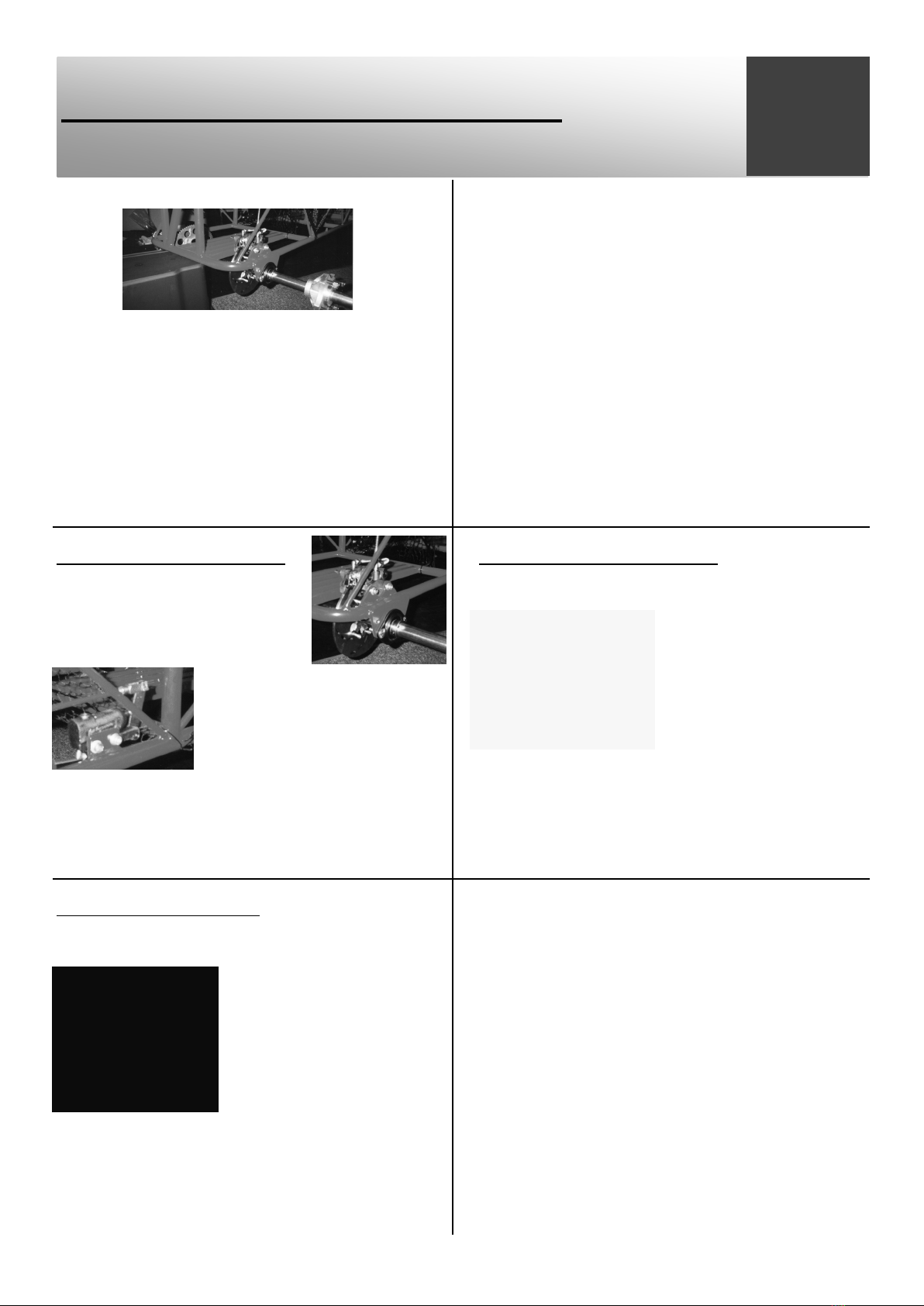
Fitting the engine & Transmission
Torque Converter.
Step One
Fit the pre-drilled eng /
transmission plate to the
chassis slide rails.
Mount the engine on top
of the plate using the pre-set holes.
Using 4x M8 x 65 hex ( up from the underside of the frame)
2x 3/8” washers per bolt (against the underside of the rails),
4x M8 washers on the top of the engine foot followed by
4x M8 nylocks. (Tighten the nylocks then back them off
enough to allow the engine to move forward to tension the
chain).
Step Two
Assemble the idle shaft
from the left hand side :
1. Collar (grub screws removed & kept safe).
2. 12 tooth sprocket with 3/16” key cut to size (14mm).
3. Collar.
4. Collar.
5. Driven pulley (With the spring boss facing left & 3/16” x
21/4” long key inserted) & collar.
All the keys must be a good tap fit.
Step Three
Mount the two box section
risers to the plate forward of
the engine (Leave a small gap
for the left hand inspection
side cover to slide between the
frame & the riser).
Using 4x M8 x 140 bolts, 3/8” penny washers (2 together
on the underside of the slide rail)
4x M8 nylocks, loosely bolt the idle shaft
bearings on top, with the bearing grub
screw bosses facing inwards. (Remove
bearing grub screws & keep in a safe
container for later use). As the risers are
mounted to the chassis sliders, the idle
shaft assembly can be introduced into the
bearings.
Step Four
When aligned the idle shaft bearing
bosses need to be secured to the idle
shaft.
This is done by using a drill bit just
smaller than the grub screw hole in the
bearing & drilling through the hole into the shaft by 1-2mm.
(Be sure the shaft is centralized in the bearings, & make sure the
risers are fully tightened before drilling).
The grub screws are then refitted to the bearings (remove any
swarf first) & through into the shaft preventing any sideways
movement.
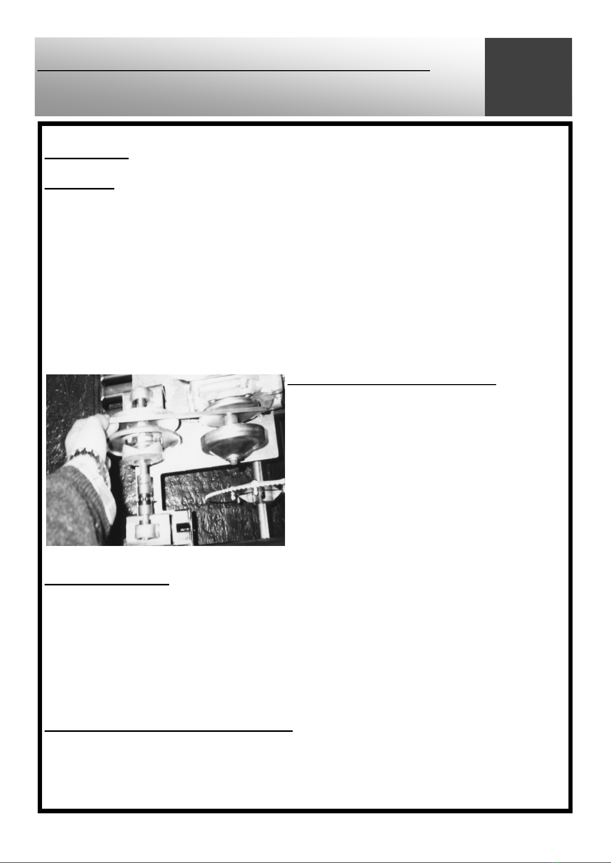
Step Five
Assemble to the very lightly greased
engine output shaft, the driver flat
pulley half tight up to the shaft
shoulder. (Driver fixed sheave #12).
Then tighten the engine down.
Tighten down the two idle shaft bearings & risers checking
alignment. Move the R.H.S collar up to the flat side of the
driven pulley (Driven fixed face #1) & using a straight edge
align the flat working faces of the
two pulleys up.
(This is important to enable the
belt run in line, otherwise rapid
belt wear & dragging will occur).
Step Six
With the R.H.S shaft collar tight up against the pulley, hold the
collar in position & push away the pulley.
Making sure the collar does not move drill through the grub screw
hole into the shaft 1-2mm.
N.B Do not drill into the key way slot or near it).
Fit the grub screw,
(remove any swarf from the
hole first) & check the pulley
alignment.