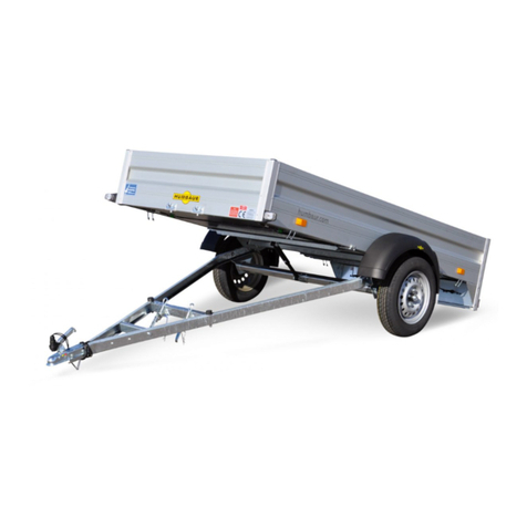
Humbaur Startrailer Plus Instruction Manual

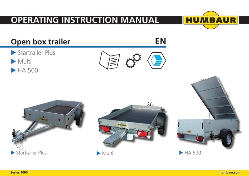
Open box trailer
Startrailer Plus
Multi
HA 500
EN
OPERATING INSTRUCTION MANUAL
Series 1000 humbaur.com
Startrailer Plus Multi HA 500

2/56 V 03/2018 Original Operang Instrucon Manual
Humbaur GmbH
Mercedesring 1
D-86368 Gersthofen
Tel: + 0049 (0) 821 24929 -0
Fax: + 0049 (0) 821 24929 -100
www.humbaur.com
info@humbaur.com
Notes on use for target group
This original operang instrucon manual is intended
for you as the user of a ready-to-use trailer.
The trailer should only be operated by users with the following
prerequisites and knowledge.
• Possession of a driver's license valid for trailer operaon.
• Healthy physical state (without any limitaons, e.g.
wheelchair user).
• Praccal experience with towing
(e.g. iniang braking, manoeuvring backwards).
• Knowledge of load securing / safe transport of a range of
goods.
• Knowledge of the relevant naonal Road Trac Act and
Road Trac Licensing Regulaons.
The contents of this operang instrucon manual are intended
exclusively for open box trailers without accessories / body com-
ponents.
Refer to specic installaon and operang instrucons for infor-
maon on how to operate accessories / body components.
Read this operang instrucon manual carefully and
completely before using your trailer for the rst me
and observe all of the instrucons, safety informaon
and warnings. Comply with the steps for handling.
• Ignoring instrucons in the manual can lead to personal
injuries and material damage.
• Ignoring instrucons may also invalidate your warranty
entlement.
• Keep this operang instrucon manual carefully for the
enre service life of your trailer.
• The operang instrucon manual should be passed on to
the new user/owner if you rent out or sell your trailer.
• It forms part of the product and also serves as a
CHECK LIST for regular inspecons.
• We advise you to keep the operang instrucon manual
in the driver's cab and to keep it at hand in case you need
to consult it.
Idencaon
WHD
1 2 3 4 5 6 7 8 9 10 11 12 13 14 15 16 17
►►►Put a cross next to the type of trailer you have
acquired.
►You will nd the dimensions / technical data of your
trailer in the vehicle documents.
Product name / trade code:
unbraked
Startrailer Plus H 752513 (1374.610) o
Mul HA 752513 (1374.910) o
braked
Startrailer Plus H 132513 (1385.610) without RSD o
Startrailer Plus H 132513 (1385.680) with RSD o
Mul HA 132513 (1385.910) without access. o
Mul HA 132513 (1385.920) with access. o
Mul HA 132513 (1385.930) with cover o
HA 500 HA 132513 (1393.900) with cover o
Accessories
►►►_________________________________________
Index
1 Safety and warning instrucons 6
2 General safety instrucons 7
3 Intended use 9
4 Foreseeable misuse 9
5 Technical data / components 9
6 Commissioning 12
7 Load distribuon / securing 23
8 Loading / unloading 27
9 Driving with the towing vehicle and
trailer 38
10 Cleaning / care 39
11 Repair / maintenance 42
12 Parking 50
13 Decommissioning/disposal 51
14 Troubleshoong 52
15 Proof of inspecon 53

Opera ng Instruc on Manual V 03/2018 3/56
Startrailer Plus (unbraked/ braked)
General view: Basic model H752513 - unbraked
General view: Basic model H132513 - braked
Rear view: Tailgate / drop sides 300 mm
Op on: with fl at cover
Op on: with high cover / frame
Op on: with side wall extension 300 mm
Technical data
unbraked braked
Weights / Loads H 752513 H 132513
Gross (permi ed GW) 750 kg 1300 kg
Net (unladen weight) 148 kg 222 kg
Load capacity (goods) 602 kg 1078 kg
Drawbar load max. 50 kg 100 kg
Tyres H 752513 H 132513
Standard 145 / 80 R13 185 / 65 R14
on rims
4-4.5Jx13 ET30
on rims
5J-6J x 14 ET30
Other permi ed
tyre sizes:
135 / 80 R13
155 R13 RF
155 / 80 R13
175 / 70 R13
155 R13 C
195 / 65 R15
185 R14 C
195 R14 C
Features
• Aluminium drop sides 300 mm high
• Rear drop side can be folded down / removed
• Front / side drop sides xed / do not fold down
• Drop side locks in the form of surface-mounted latches
• Screen oor plate 12 mm thick
• Round bu ons for securing a tarpaulin / cover net using
elas c cable
• 3 pairs of e-down brackets for load securing (400 daN)
Op onal accessories
• Flat cover
• Crossbar for at cover
• Frame / high cover
• Side wall extensions (300 mm)
• Prop stands
• Jockey wheel, wheel chocks (for unbraked trailer)

4/56 V 03/2018 Original Opera ng Instruc on Manual
Mul (unbraked / braked)
General view: Basic model H752513 - unbraked
General view: Basic model H132513 - braked
Rear view: Tailgate / drop sides 150 mm
Op on: Motorcycle rocker, loading ramps, side extension 1x
Op on: Flat cover / side extensions 2x
Op on: Aluminium cover / side extensions 3x
Technical data
unbraked braked
Weights / Loads H 752513 H 132513
Gross (permi ed GW) 750 kg 1300 kg
Net (unladen weight) 180 kg 215 kg
Load capacity (goods) 570 kg 1085 kg
Drawbar load max. 50 kg 100 kg
Tyres H 752513 H 132513
Standard 145 / 80 R13 185 / 65 R14
on rims
4-4.5Jx13 ET30
on rims
5J-6J x 14 ET30
Other permi ed
tyre sizes:
135 / 80 R13
155 R13 RF
155 / 80 R13
175 / 70 R13
155 R13 C
195 / 65 R15
185 R14 C
195 R14 C
Features
• Aluminium drop sides 150 mm high
• Rear drop side can be folded down / removed
• Front / side drop sides xed / do not fold down
• Drop side locks in the form of surface-mounted latches
• Screen oor plate 12 mm thick
• Round bu ons on side wall extensions for securing a
tarpaulin / cover net using elas c cable
• 3 pairs of e-down brackets for load securing (400 daN)
• Ramp slot pre-installed (without loading ramps)
Op onal accessories
• Flat cover
• Crossbar for at cover
• Frame / high cover
• Side wall extensions (300 mm)
• Prop stands
• Jockey wheel, wheel chocks (for unbraked trailer)
• Motorcycle rocker
• Aluminium cover on side wall extension
• Loading ramps (made of aluminium, approx. 9 kg / pair)

Opera ng Instruc on Manual V 03/2018 5/56
HA 500 (braked)
General view: with aluminium cover and supports
Rear view: Tailgate / drop sides 500 mm
Rear view: Aluminium cover open
Rear view: Tailgate / aluminium cover open
Rear view: Aluminium cover can be locked
Rear view: Supports for bicycle stand, for example
Technical data
braked
Weights / Loads H 132513
Gross (permi ed GW) 1300 kg
Net (unladen weight) 257 kg
Load capacity (goods) 1043 kg
Drawbar load max. 100 kg
Tyres H 132513
Standard 185 / 65 R14
on rims
5J-6J x 14 ET30
Other permi ed
tyre sizes:
195 / 65 R15
185 R14 C
195 R14 C
Features
• Aluminium drop sides 500 mm high
• Rear drop side can be folded down / removed
• Front / side drop sides xed / do not fold down
• Latches on rear drop side, recessed
• Screen oor plate 12 mm thick
• Aluminium cover with 2x crossbars, supported at front
• 3 pairs of e-down brackets for load securing (400 daN)
Op onal accessories
• Prop stands

6/56 V 03/2018 Original Operang Instrucon Manual
1 Safety and warning instrucons
1.1 Signal words
In this manual, you are informed about the dierent degrees
of risk as follows:
Possible risk with high level of risk
Not prevenng this risk would result in fatal or serious injuries.
Possible risk with medium level of risk
Not prevenng this risk could result in fatal or serious injuries.
Possible risk with low level of risk
Not prevenng this risk could result in slight or minor injuries.
Possible risk of material damage
Not prevenng this risk could result in material damage.
1.2 Text signs
►(Arrow) Request for acon
• (Bullet point) List
1. (Number) List of components
DANGER
WARNING
CAUTION
NOTICE
1.3 Warning signs / pictograms
1.3.1 Danger signs:
Warning about danger points!
Be careful - people could be injured!
Risk of crushing!
For limbs such as: Hands / ngers / feet.
Crushing / impact risk!
For body / body parts.
Risk of falling!
People may fall and injure themselves.
Risk of slipping!
On smooth / wet / slippery surfaces.
Risk of tripping!
Obstacles on moving surfaces / in the working area.
1.3.2 Prohibitory signs:
Access prohibited for unauthorised persons!
Spraying with water prohibited (high-pressure cleaner)!
Standing on surface / area prohibited!
Climbing up prohibited!
1.3.3 Mandatory signs:
Important informaon - take note!
Note and observe to ensure safe use.
Read operang instrucon manual beforehand!
Wear sturdy footwear!
Wear protecve gloves!
Disconnect from the mains power!
Carry out work in 2-man operaon!
1.3.4 Other important pictograms:
Dispose of old tyres correctly!
Do not dispose of tyres in the environment!
Problem waste!
Do not dispose of waste in the environment / with the
domesc waste!
Banksman / second person required!
Risk of pollung the environment!

Operang Instrucon Manual V 03/2018 7/56
2 General safety instrucons
As the operator of a trailer, you are obliged to comply
with naonal and internaonal health and safety
requirements.
• In Germany, the German Road Trac Act (StVO) and
Product Safety Act (ProdSG) apply as well as their
regulaons.
• Any addional unauthorised added structures on the
trailer can increase the potenal risk.
►Only use original Humbaur spare parts and accessories.
►Find out which accessories you are allowed to aach
independently and what needs to be carried out in a
specialist workshop.
Furthermore, as a road user, you are obliged to observe
all naonal regulaons for driving a vehicle with trailer
and to comply with your obligaons as the owner of a
commercial vehicle.
• This includes carrying out regular service and
maintenance and periodically subjecng your trailer to a
full technical inspecon.
2.1 Sckers on the product
• Your aenon is drawn to the residual risks on the trailer.
►Pay aenon to the instrucons and comply with the
maximum values / forces specied.
VORSICHT CAUTION
Nichteinhaltung der Stützlast
Unfallgefahr / Schlingergefahr!
Verteilen Sie die Ladung so, dass keine
negative Stützlast entsteht bzw. die
max. zul. Stützlast eingehalten wird.
Noncompliance with vertical load
Risk of accident / skidding!
When distributing the cargo, a negative
vertical load mustn’t arise and the max.
perm. vertical load has to be adhered.
620.00404_A
WARNUNG WARNING
Gefahr des Radlösens!
Lose Radmuttern führen zu Unfällen.
Radmuttern nach 50 km
und nach jedem Radwechsel
nachziehen.
Danger of a loss wheel!
Loose wheelnuts result in accidents.
Check wheelnuts for thightness
after the first 50 km and after
each subsequent wheel change.
620.00037_C
DIN Zurrpunkte
400 daN (kg)
min. 30 °
620.00031_B
2.2 For people
WARNING
Children playing in the vicinity of your trailer!
Trailers are not toys! Children are unable to properly assess the
risks associated with a trailer and could injure themselves playing
with the trailer.
►Do not allow children to play unsupervised
near your trailer.
►Keep children well away when manoeuvring
with the trailer.
Zulässige Stützlast
Permissible vertical load
max. 50 kg
620.00026_A
2.3 While driving
WARNING
Excessive speed / speed not adapted!
The load could come loose and fall o - risk of snaking / acci-
dents!
►Pay aenon to the naonal regulaons in your country
regarding permissible top speed.
►Keep to the maximum permissible towing speed.
Poor road / extreme weather condions!
If the road surface is uneven, has potholes, or if the weather is
bad, e.g. storm, snow, slipperiness, ice, hail, your trailer could
start snaking - risk of an accident!
►Adapt your speed to the prevalent road and weather
condions.
Gusts of wind / side wind!
In the event of strong gusts of wind / side winds which can occur
near bridges, tunnels, cungs through woods, sound protecon
walls or when overtaking lorries, if you steer sharply it could
cause your trailer to start snaking - risk of an accident!
►Slowly reduce your speed and adapt your driving to the
weather condions.
Objects on the trailer body!
Objects such as branches, ice, snow, etc. can be thrown on the
road during the journey – accident risk!
►Remove all objects, such as branches, ice, snow, water
loads etc. from the body of the trailer.

8/56 V 03/2018 Original Operang Instrucon Manual
WARNING
Worn tyre prole / incorrect tyre pressure!
The tyres can burst when driving along and the trailer will start to
break away. The braking distance increases.
The trailer may start to skid, p over and be uncoupled from the
towing vehicle.
►Regularly check the tyres.
►Check the tyre pressure, prole depth and condion of
the tyres.
Loose wheel nuts / wheel bolts!
The wheel nuts / wheel bolts could come loose.
Trailer could lose a wheel - risk of snaking / an accident!
►Aer the rst 50 km, aer the rst drive with a load, and
every me aer changing the tyres, ghten the wheel
nuts / wheel bolts.
►Check that the wheel nuts / wheel bolts are seated se
curely at regular intervals.
WARNUNG WARNING
Gefahr des Radlösens!
Lose Radmuttern führen zu Unfällen.
Radmuttern nach 50 km
und nach jedem Radwechsel
nachziehen.
Danger of a loss wheel!
Loose wheelnuts result in accidents.
Check wheelnuts for thightness
after the first 50 km and after
each subsequent wheel change.
620.00037_C
Unsecured / poorly secured load!
The load can shi during the trip and could unbalance the trailer
or could be directly thrown o the trailer.
►Tie down the load before driving o.
►Ensure that the load is adequately secured when taking a
break.
►Pay aenon to naonal regulaons on load securing.
Driving without the safety cable / arrester cable at-
tached!
In the event of the trailer becoming detached or if the coupling
fails, the trailer will not be braked / caught - risk of accident!
►Connect the safety cable / arrester cable to the towing
vehicle.
►Pay aenon to the naonal regulaons on this.
CAUTION
Non-compliance with the drawbar load!
Exceeding the max. permissible drawbar load / not reaching the
min. drawbar load can cause accidents - risk of snaking!
►Distribute the load so that no negave drawbar load is
created or that the maximum permissible drawbar load is
complied with.
►Do not exceed the maximum permissible drawbar load
of the towing vehicle and the trailer coupling.
►Observe the informaon on the maximum
permissible drawbar load in your vehicle papers
and the trailer coupling.
►Observe the informaon on the maximum permissible
drawbar load in the COC papers, Secon 19.
VORSICHT CAUTION
Nichteinhaltung der Stützlast
Unfallgefahr / Schlingergefahr!
Verteilen Sie die Ladung so, dass keine
negative Stützlast entsteht bzw. die
max. zul. Stützlast eingehalten wird.
Noncompliance with vertical load
Risk of accident / skidding!
When distributing the cargo, a negative
vertical load mustn’t arise and the max.
perm. vertical load has to be adhered.
620.00404_A
Worn trailer coupling!
A worn trailer coupling leads to poor road handling of the trailer -
risk of snaking!
►Make sure that the coupling is not worn / deformed
before driving o.
►Carry out regular maintenance of the coupling to prevent
wear.
Inadequate / faulty lighng!
It is dicult to see the trailer or it will not be seen in me by
other road users - risk of accident!
►Before seng o, check that the lighng on the trailer is
working and is not covered by the load.
►Remedy any defects to the lighng.
2.4 During loading / unloading
WARNING
Inadequate lighng!
When loading / unloading, the lighng on the trailer could be
covered up - meaning the trailer is dicult for road users to see
(at dusk /in the dark) - risk of accident!
►Make sure that road trac safety is not impaired when
loading / unloading the trailer.
►If necessary, use addional signalling devices, e.g. signs,
barriers.
WARNUNG WARNING
Unzureichende Beleuchtung
beim Be- und Entladen!
Erhöhte Unfallgefahr.
Sichern Sie den Anhänger mit
zusätzlichen Signaleinrichtungen.
Inadequate lighting during
loading and unloading!
Increased risk of accidents.
Secure the trailer with additional
signalling devices.
620.00038
2.5 When parking
WARNING
Unsecured trailer!
The trailer can start moving out of control and could injure people
- risk of accident!
►Secure the trailer against rolling away.
►Place the wheel chocks under the wheels.
►Apply the parking brake.
►Park the trailer on ground which is as level as possible
(not on a slope).
►Park the trailer so that it does not pose any further risks.
►Secure the trailer against being used by unauthorised
third pares (an-the device).
Standing / hanging trailer on its end!
The trailer could p up and fall down.
People could be knocked / crushed.
►Secure the trailer against falling over.
►Tie the trailer to a solid wall.
Opera ng Instruc on Manual V 03/2018 9/56
3Intended use
• Transpor ng goods.
• Opera on within the permissible gross weight
(see informa on in registra on cer cate part I + II).
• Opera on with a suitable permi ed towing vehicle and a
permi ed coupling.
• Only operate if in perfect technical condi on.
• Comply with all warning / safety no ces on the trailer and
in the complete product documenta on (opera ng
instruc ons, licensing papers, etc.)
• Complying with the maintenance and repair work as
speci ed by the manufacturer.
• Regular care / cleaning of the trailer to remove dirt /
foreign bodies.
• Regularly presen ng the trailer for technical examina on
/ inspec on.
• Opera ng with even weight distribu on of load.
• Only drive with an appropriately secured load.
The driver of the towing vehicle is responsible for securing
the load and the equipment for load securing.
• Adhere to the legally prescribed and permi ed maximum
driving speed and adapt the speed when driving on bad
roads or in bad weather condi ons.
• Loading and unloading is only permi ed in secured areas
or on public roads a er addi onal securing measures.
• Securing the trailer against rolling away when parked.
The following condi ons for opera ng a trailer
up to 3.5 t within the context of “Intended use” must be
met:
1. Trailer licensing
2. Driving license for driving with a trailer
3. Presence of vehicle documents and type plate
4. Periodic examina on / general inspec on
4 Foreseeable misuse
• Transpor ng persons / animals.
• Transpor ng hot materials (e.g. tar).
• Transpor ng hazardous goods such as chemicals or
similar.
• Driving with a poorly secured / unsecured load.
• Driving with bad load distribu on (load one-sided or in
one point).
• Making structural changes to the trailer that were not
approved by the manufacturer.
• Unauthorised technical altera ons to the trailer.
• Exceeding the maximum permissible drawbar load, load
capacity or trailer load.
• Using unapproved spare parts or accessories.
• Driving with a faulty ligh ng system or malfunc oning
ligh ng system.
• Driving with vehicle body not closed.
• Maintenance of safety-relevant components, such as
brakes, drawbar, etc. by a layperson.
• Removing the type plate or VIN on the trailer or making
them illegible.
• Driving at an inappropriate / excessive speed in poor
weather condi ons / road condi ons.
• Parking without taking safety precau ons to prevent
the trailer from rolling, such as: applying the hand brake,
using wheel chocks, parking on a level surface.
• Opera ng the trailer with visible wear of parts or
breakage of safety-relevant components and accessories.
• Opera ng the trailer when it is damaged, which can cause
danger on public roads and could also lead to personal
injury.
• Passing on / ren ng out the trailer without handing over
the opera ng instruc on manual “documenta on” or
providing an explana on of the known residual risks.
As the manufacturer, we do not accept any liability for
personal injury or material damage caused by foreseea-
ble misuse.
5 Technical data / components
You will nd the technical data for your trailer in the following
places:
• Vehicle documents:
Registra on cer cate part II (RC II) and
Registra on cer cate part I (RC I),
CE cer cate of conformity for complete
vehicles “COC - Cer cate of Conformity”
• Type plate (permanently a ached to the trailer)
►If you lose the vehicle documents, you need to report it to
the police.
• You can request a second copy of the vehicle documents
a er proving the loss.
5.1 Type plate / VIN
• A type plate is ed to every trailer.
The plate is permanently a ached on the right of the
front or side drop side viewed in the direc on of travel.
• The type plate provides informa on about the type of
trailer and its origin as well as the maximum permi ed
loads / weights.
• The VIN (Vehicle Iden ca on Number) allows us, the
manufacturer, to iden fy your trailer accurately and
provide prompt assistance.
►If you have any queries about your trailer, specify the last
6 numbers of the VIN.
H - 002
Example: VIN engraved / type plate

10/56 V 03/2018 Original Opera ng Instruc on Manual
H - 001
Humbaur GmbH
Humbaur GmbH Mercedesring 1 86368 Gersthofen
GERMANY humbaur.com
WHDXXXXXXXXXXXXXX
e1*2007/46*XXXX
1300 kg
0 -
1 -
100 kg
1300 kg
1
2
3
4
5
6
7
Example: Type plate
1. Manufacturer
2. Number EEC opera ng license
3. 17-digit VIN
4. Max. permi ed total weight
5. Drawbar load
6. Max. permi ed weight: Axle 1
7. Manufacturer's address
The iden ca on informa on (type plate, engraved VIN)
must remain legible during the en re life cycle of the
trailer.
• The VIN on your trailer is also engraved on the right of the
frame / xed front or side drop side viewed in the
direc on of travel.
►Never remove, obscure or paint over the type plate and
the engraved VIN on the frame / drop side.
d
c
b
a
e
H - 48
f
Startrailer Plus Startrailer Plus Mul Mul HA 500
H 752513 H 132513 HA 752513 HA 132513 HA 132513
aLength 3585 3765 3585 3765 3760
bCoupling height 465 450 465 450 465
cLength of cargo bed 2510 2510 2510 2510 2510
dWidth of cargo bed 1310 1310 1310 1310 1310
eWidth 1760 1800 1760 1800 1810
fHeight of drop side 300 300 150 150 500
Approximate dimensions in mm

Opera ng Instruc on Manual V 03/2018 11/56
5.2 Components for trailers up to 3.5 t
The following is a list of typical basic components for trailers up
to 3.5 t.
You can nd a detailed descrip on of the func on, type and
intended use of the components in this opera ng instruc on
manual.
1. Latch
2. Side re ector (orange)
3. Side drop side
4. Mudguard
5. Wheel (tyre)
6. Tie-down point
7. Loading pla orm / cargo bed
8. Front retro-re ector / posi on lamp
9. Wheel chocks (only on braked version)
10. Front drop side
11. V drawbar
12. Brake linkage
13. Jockey wheel
14. Hand brake
15. Drawbar support
16. Rubber sleeve
17. Safety cable (braked) / arrester cable (unbraked)
18. Coupling head
19. Parking socket for plug
20. Loading ramp slot / number plate holder (op onal)
21. Tailgate
22. Underride protec on
23. Mul func onal light
24. Plas c support
25. Rear re ector (red)
26. Stanchion with cap
27. V drawbar without overrun device (unbraked version)
H - 50
2
1
3
4
5
9
8
10
11 12 13 14 15 16 17
18
19
20
6
7
21
22
23
24
26
27
25

12/56 V 03/2018 Original Opera ng Instruc on Manual
6 Commissioning
►Carry out the following steps to drive with a trailer.
The towed trailer must always be approved and free of
defects!
Commission on solid, stable and level ground. Do no ob-
struct the tra c on the roads. Do not impede road users
/ people and do not expose them to risks.
►Posi on towing vehicle in front of the trailer.
- Trailer should be aligned with the towing vehicle
(in a straight line).
►Secure the towing vehicle to prevent it from rolling away.
►Release hand brake on the trailer (if present).
►Couple the trailer / secure safety cable, arrester cable.
►Remove wheel chocks and secure in brackets.
►Raise jockey wheel / supports (if present).
►Plug electric systems into socket on car.
►Carry out departure check.
To avoid accidents and prevent personal injury and
material damage, it is important to carefully check the
condi on and func on of the trailer before se ng o .
The listed components may vary depending on your
trailer equipment and type.
If the holder commissions and licences a trailer with
defects, then they will be prosecuted in Germany with
nes and points on their licence according to the
German Road Tra c Act (StVO).
►Check your trailer regularly for defects.
►Rec fy faults / defects of have them repaired immediately
in a specialist workshop.
H - 003
Example: Trailer unbraked, coupled
►Carry out a departure check.
Components Tes ng
Coupling head has engaged properly and is secured?
Safety / wear indicator is in the green zone?
Safety cable / arrester cable has been securely a ached / hooked in to the retainer on the car coupling?
Hand brake lever (if present) is released?
Plug connec on (electric system) is rmly connected and secured?
Electric cable does not rest / drag on the ground and is not wound too ghtly around the drawbar?
Jockey wheel (if present) has been cranked up correctly and secured?
Wheel chocks are removed and secured in holders?
Load weight is evenly / correctly distributed and secured against sliding around / ed down?
Tyres are lled to the correct tyre pressure; do not show any damage and have su cient
pro le?
Lights, posi on lamps are working / undamaged?
An -the device has been removed and stowed away safely?
Tailgate is closed and secured or removed for the transporta on of long materials?
A achments / accessories (e.g. cover,
tarpaulin) have been locked and secured?
Departure checklist
H - 004
Example: Trailer closed / ligh ng func ons

Opera ng Instruc on Manual V 03/2018 13/56
6.1 Hand brake without push bu on
Func onal explana on
• A hand brake (parking brake) is designed to prevent the
trailer from rolling away.
• Braked trailers have an overrun device with brake linkage
and brake compensa on.
• Unbraked trailers do not have a hand brake / parking
brake.
• The hand brake without a push bu on needs to be moved
beyond a ratchet point.
WARNING
Releasing hand brake on unsecured trailer!
The trailer could start moving spontaneously - risk of
impact!
►Couple your trailer to the car.
►Release the hand brake once your trailer is secured with
wheel chocks.
Driving with the hand brake applied / not com-
pletely released!
The brake shoes could block the wheels - Risk of snak-
ing / accidents! The brakes get hot.
►Make sure that the hand brake is completely released
before driving o .
CAUTION
Opera ng the hand brake!
You could pinch / crush hands / ngers on the draw-
bar / ball head.
►Operate the hand brake slowly and carefully.
►Make sure that your hand and body are outside the
crushing / movement area.
Engaging the hand brake
1. Hand brake lever, engaged / top
2. Spring mechanism, extended
3. Jockey wheel (in parking posi on)
►Wind down the jockey wheel (3) un l it reaches the oor.
►Pull up the hand brake lever (1) beyond the resistance
point so that the brake is fully applied.
►Push the trailer back slightly.
The spring mechanism (2) fully applies the hand brake.
CAUTION
Uncontrolled movement of the trailer when
the hand brake is applied!
Trailer could roll back approx. 25-30 mm when uncoupled un l
the full braking force is applied.
►Always apply the hand brake completely - if applicable,
push the trailer backwards slightly so that the full braking
force is reached.
►When parking your trailer, make sure there is enough
space behind it.
H - 006
1
3
2
Releasing hand brake
H - 005
1
2
3
Releasing hand brake
1. Hand brake lever, released / down
2. Spring mechanism, retracted
3. Jockey wheel (in driving posi on)
►Push the hand brake lever (1) beyond the ratchet point
completely downwards towards the coupling.
The spring mechanism (2) is retracted / released.

14/56 V 03/2018 Original Opera ng Instruc on Manual
6.2 Hand brake with push bu on
Hand brake with push bu on (parking posi on)
1. Release bu on
2. Hand brake lever, engaged / top
3. Gas strut, extended
4. Brake linkage, applied
Func onal explana on
• Hand brakes with a push bu on do not need to be pushed
beyond a ratchet point.
• The hand brake is released using a push bu on.
On a hand brake with toothed segments, the hand brake
lever needs to be applied to the last tooth and needs to
be released to the rst tooth.
H - 007
1
2
3
4
Engaging the hand brake
1. Hand brake lever
2. Brake, applied
3. Jockey wheel (in parking posi on)
4. Gas strut
►Wind down the jockey wheel (3) un l it reaches the oor.
►Pull the hand brake lever (1) as far up as possible so that
the brake (2) is fully applied.
►Push the trailer back slightly.
The gas strut (4) fully applies the hand brake.
H - 008
2
1
3
4
Releasing hand brake
1. Release bu on
2. Hand brake lever
3. Gearing / Locking system
►Pull the hand brake lever (2) slightly upwards while at the
same me pressing the release bu on (1).
►Guide the hand brake lever all the way down towards the
coupling.
The gearing is released by the locking mechanism (3).
The hand brake lever rests on the overrun device.
Hand brake released (driving posi on)
H - 009
H - 009
1
2
3
H - 010

Opera ng Instruc on Manual V 03/2018 15/56
6.3 Trailer safety
Func onal explana on
• Unbraked trailers (up to 750 kg) are ed with an arrester
cable.
• The arrester cable prevents the trailer from coming
uncoupled from the car in the event of the trailer coupling
disconnec ng.
• Braked trailers (from 750 kg to 3500 kg) are ed with a
safety cable.
• In the event of the trailer coming unhooked, the safety
cable will trigger automa c braking.
Driving without the arrester / safety cable a ached is
prohibited by law!
A aching the arrester / safety cable incorrectly is dan-
gerous and can result in nes in other countries!
Make sure the safety cable loop is su ciently long to
allow cornering.
State of technology:
The safety cable may not be laid in a loop over the trailer cou-
pling. Where technically possible, it should be a ached through a
ring or an exis ng drilled hole in the coupling.
The snap hook on the safety cable is hooked into the pre-mount-
ed ring on the body, thus securing the trailer.
The car coupling as a mechanical coupling device must be state of
the art (Direc ve ECE-R55).
The manufacturers of brackets must include a achment points
for secondary couplings (arrester / safety cable) or provide devic-
es which ensure that the trailer comes to a stands ll in the event
that it comes uncoupled.
Pay a en on to the safety informa on and opera ng
instruc ons from the manufacturer of the trailer
coupling on the car.
Driving with arrester / safety cable incorrectly a ached!
The arrester / safety cable could detach from the ball head while
driving. If it came uncoupled, the trailer would be unsecured and
can't be braked - risk of accidents!
►Before se ng o , check that the arrester / safety cable is
correctly and securely hooked into or threaded through a
xed ring / drilled hole / mechanical device - tying a loop
around the ball head is inadequate!
►If necessary, retro t an addi onal a achment device for
the arrester / safety cable if you have an older model
coupling (according to Direc ve EEC 94/20).
DANGER
B - 000
B - 001
Ball head couplings according to ECE-R55
Example: Coupling with ring
1. Ball head coupling
2. Ring
3. Snap hook, a ached
Ball head couplings according to EEC 94/20
Example: Coupling with clamping device
1. Universal clamping device
►If you have an older model coupling, retro t a universal
clamping device (1) according to EEC 94/20.
Pay a en on to the installa on instruc ons to mount
the universal clamping device correctly (# 700.00986).
H - 011
2
1
3
H - 012
1

16/56 V 03/2018 Original Opera ng Instruc on Manual
6.3.1 A aching the arrester cable (unbraked)
Arrester cable a ached
1. Hook, locked
2. Arrester cable, secured
►Place the coupling head onto the ball head on the car
coupling - make sure that it is locked.
►Pull the locking mechanism on the clamping device (1)
while simultaneously inser ng the arrester cable (2) in a
loop.
►Release the locking mechanism.
The arrester cable is inserted and secured.
►Check that the required swivel range for the ball head
coupling is ensured.
H - 013
2
1
6.3.2 A aching the safety cable
Safety cable a ached
1. Hook, locked
2. Safety cable with spring hook, secured
►Place the coupling head onto the ball head on the car
coupling - make sure that it is locked.
►Pull the locking mechanism on the clamping device (1)
while simultaneously inser ng the safety cable (2) in a
loop.
►Release the locking mechanism.
The safety cable is inserted and secured.
►Check that the required swivel range for the ball head
coupling is ensured.
►Ensure that the spring hook (2) is closed.
H - 014
2
1
6.3.3 Securing the snap hook (DIN 5299)
Safety cable a ached using snap hook
1. Ball head coupling, retractable
2. Ring, on side
3. Safety cable with snap hook, secured
►Press in the snap fastener on the snap hook.
►Hook the snap hook (3) onto the ring (2).
The snap fastener on the snap hook closes automa-
cally once it has been released.
►Make sure that the safety cable is not dragging on the
ground.
The snap hook must meet standard DIN 5299 and have a
length of 70 mm and a diameter of 7 mm (shape C /
load-bearing capacity 180 kg).
Only this design of snap hook may be a ached directly
to the coupling on the car!
Smaller snap hooks may only be hooked into the safety
cable in a loop!
2
1
3
H - 015

Opera ng Instruc on Manual V 03/2018 17/56
6.4 Coupling / uncoupling the trailer
Func onal explana on
• A coupling head is used on car trailers ed with a
Ø 50 mm ball head moun ng.
• Always note and observe the maximum drawbar load and
trailer load of the ball head coupling.
Impact risk during coupling process!
Body parts in the area around the coupling may be
crushed or struck during the coupling process.
►Manoeuvre the towing vehicle carefully towards the
trailer.
►Make sure that no one is standing in the area
around the coupling.
► If necessary, arrange for an assistant to help
manoeuvre the vehicle using hand signals.
Operate the coupling head!
Your hands / ngers may be crushed between the
coupling head and ball head coupling on the car.
►Always hold the coupling by the handle.
- Do not grasp the ball moun ng (spherical cup) from
below.
►Hold the drawbar / draw tube / handle when manoeu
vring the trailer.
►Only release the hand brake once the trailer is securely
coupled.
►Remove the wheel chocks.
WARNING
6.4.1 Coupling head
unbraked braked
1. Safety catch
2. Handle
3. Wear indicator
4. Safety display
5. Plug lock (an -the device)
The ball head on a car trailer coupling as well as the
coupling head on the trailer are subject to wear and tear
during opera on. This depends on the driving style as
well as adhering to regular maintenance of the ball head
and the trailer coupling. The di erent wear indicators on
the coupling head are there for your safety. These
display the status and wear of the ball head and the
coupling cup / spherical cup.
Driving with a worn coupling head!
Trailers can become detached, skid or p over while driving - risk
of accident!
►Do not drive with a worn / dirty coupling head.
►Before se ng o , make sure that the coupling head
has clicked into place and the safety indicator is in the
green / posi ve area.
►A ball head on the car coupling with a diameter of less
than 49 mm needs to be replaced.
H - 018
2
1
3
1
3
4
4
2
5
WARNING
Wear check
Ball coupling from below
1. Spherical cup
2. Coupling cup
Checking coupling wear
►Regularly inspect the state of the coupling cup (2) and the
spherical cup (1).
►Before every trip, check the condi on of the ball head on
your car trailer coupling.
- The ball head must not have any visible grooves.
unbraked braked
►Marking is outside the wear indicator range or within
area X
• The coupling on the trailer has not been properly coupled.
►Marking is within green / + / OK area
• Ball head coupling is in new condi on.
• Wear of the ball head is in the permi ed range.
►Marking is within red / —/ STOP / area
• Ball head on the car trailer coupling or trailer coupling
head is worn.
H - 016
1
2
H - 017
2
3
1
2
1
3

18/56 V 03/2018 Original Opera ng Instruc on Manual
6.4.2 Coupling / uncoupling
Maximum swivel range
1. Trailer coupling (ball head) on towing vehicle
2. Coupling head (trailer)
►Before connec ng up your trailer for the rst me, make
sure that the car trailer coupling is aligned with the cou
pling head on the trailer:
• Height of both couplings
• Design of the car coupling
• Electrical connec on (plug: 7 or 13-pin)
Only to be used with ball head coupling according to
Direc ve 94/20/EC or ECE R55 with a 50 mm Ø ball
head.
Limited swivel range!
Short / incorrect car couplings can limit the necessary swivel
range - trailer could come uncoupled.
►Use a trailer coupling with a free-standing ball head.
►Before se ng o , check that your car coupling allows the
necessary swivel movement horizontally and ver cally.
20°
20°
25°
25°
1
2
H - 019
WARNING
The height of the coupling head
Coupling heads for trailers are built to DIN 74058 or ISO
1103 with a height of 430 ± 35 mm.
►Do not drive with a trailer which is at an extreme angle to
the car (or lted forwards or backwards).
The ball head must be greased to prevent premature
wear and the forma on of grooves on the ball head and
in the coupling housing (spherical cup).
Trailer at an angle!
The required swivel range is limited / increased coupling wear /
road handling is impaired - trailer could come uncoupled.
►Before connec ng up your trailer for the rst me, check
that the height of the ball head on the car is in the range
of 395 - 465 mm between the road surface and the mid
dle of the ball head.
►Adjust the height of the ball head coupling on the car or
pad out the overrun device if the height di erence is too
great.
►If necessary, have a di erent ball head coupling a ached
to your towing vehicle in a specialist workshop.
H - 020
H - 020
430 ±35
WARNING
Coupling process
Coupling unbraked trailer
1. Handle
2. Safety catch
3. Spherical cup
4. Ball head
►Press the safety catch (2) all the way in.
►Pull the handle up (1) completely and release the safety
catch.
►Place the spherical cup (3) on the ball head (4).
If there is su cient drawbar load, then the coupling
head will click into place by itself.
If there is insu cient drawbar load:
►Press the coupling head down manually un l it clicks into
place.
►Check that the coupling head is seated correctly.
- The safety catch must lock the handle into place.
- The wear indicator is in the green / + area.
WARNING
Deformed handle and safety catch!
Damage / deforma on can cause malfunc ons!
►Do not stand on the handle.
►Have the ball head coupling replaced if faulty.
H - 021
3
4
1
2

Opera ng Instruc on Manual V 03/2018 19/56
Braked trailer coupled
1. Handle, secured
2. Safety catch, clicked in place
3. Safety cable, a ached
4. Electric plug, plugged in
5. Locking mechanism
Check
►Check the visual wear / safety indicator.
It must be within the green / +area.
A empt to li :
►To check, pull the handle upwards (1) without actua ng
the safety catch (2).
The coupling head may not li o the ball head.
►A ach the arrester/ safety cable (3) to the device or an
eye on the vehicle’s drawbar
►Connect the electric plug (4) to the socket on the car’s
trailer coupling.
H - 022
1
2
3
4
5
Uncoupling process
Uncoupling unbraked trailer
1. Handle
2. Safety catch
3. Spherical cup
4. Ball head
Unbraked trailer
►Secure the trailer against rolling away.
►Release the arrester cable from the ball head coupling.
►Release the electric plug from the car socket.
►Unlock the handle on the locking mechanism.
►If applicable, lower the jockey wheel / support device.
►Press the safety catch (2) all the way in.
►Pull the handle (1) all the way up.
►Li the spherical cup from the ball head (4).
The trailer is uncoupled from the car.
H - 023
2
3
4
1
Uncoupling braked trailer
1. Handle
2. Safety cable
3. Spherical cup
4. Ball head
Braked trailer
►Secure the trailer against rolling away.
►Apply the parking brake.
►Release the safety cable (2) from the ball head coupling.
►Release the electric plug from the car socket.
►Unlock the handle on the locking mechanism.
►Press the safety catch (if present) all the way in.
►Pull the handle (1) all the way up.
►Adjust / wind down the jockey wheel to li the spherical
cup (3) from the ball head (4).
The trailer is uncoupled from the car.
3
4
1
2
H - 024

20/56 V 03/2018 Original Opera ng Instruc on Manual
6.5 Wheel chocks
Removing the wheel chocks
Wheel chock secured (driving posi on)
1. Lever
2. Wheel chock
3. Holder
Func onal explana on
• Wheel chocks prevent the trailer from rolling away.
• The wheel chocks can be stowed at the front right / le or
on the drop side.
• Wheel chocks are only standard on braked trailers.
►Press in the lever (1) on the holder (3).
►Slide out the wheel chock (2) at the same me.
►Remove the wheel chock from the holder.
WARNING
Unsecured trailer at risk of rolling!
An uncoupled parked trailer could start moving spon-
taneously - risk of accident!
►Place the wheel chocks (right+le ) under the wheels
before uncoupling your trailer.
►Make sure that the wheel chocks are posi oned correctly
when the trailer is parked on a slope.
H - 025
1
2
3
Placing the wheel chocks
H - 026
1
Wheel chock (parking posi on)
1. Wheel chock, posi oned
►Check the ground condi ons.
Make sure that the ground is su ciently stable.
If the ground is so (e.g. sandy, loose chippings), place a
solid base underneath.
►Place the complete surface of the wheel chocks under the
wheels.
Consider the direc on of inclina on of the trailer.
The trailer has been secured to prevent it from rolling away.
Securing wheel chocks
►Slide the wheel chock into the holder un l it engages - a
clicking noise can be heard.
The lever prevents the wheel chock from falling out.
WARNING
Unsecured wheel chocks!
The wheel chocks could fall out while driving - risk of accidents!
►Make sure that the wheel chocks are secured in the
holders before driving o .
►Check the holders for damage at regular intervals.
6.6 Support devices
6.6.1 Drawbar support
Support unbraked braked
1. Drawbar support (unbraked trailer)
2. Ring (for guiding the safety cable)
3. Drawbar support (braked trailer)
Func onal explana on
• The drawbar support is used to support the drawbar
when parking your trailer.
• The drawbar support protects the overrun device and the
coupling from damage if it were to fall down.
CAUTION
Parking trailer on drawbar!
You could crush your feet / hands under the drawbar
support.
►Carefully support your trailer on the drawbar support.
►Use .
►Keep your feet away from the danger zone when
lowering the drawbar.
The safety cable must be fed through a guide
e.g. a ring (2).
H - 027
1
2
3
This manual suits for next models
2
Table of contents
Other Humbaur Utility Vehicle manuals

Humbaur
Humbaur 4000 Series User manual

Humbaur
Humbaur 1000 Series User manual

Humbaur
Humbaur Rexus 5000 Series User manual

Humbaur
Humbaur Steely 1260.400 User manual

Humbaur
Humbaur 10000 Series User manual

Humbaur
Humbaur FTK 4000 Series User manual

Humbaur
Humbaur HU Series User manual

Humbaur
Humbaur Startrailer Plus Series Instruction Manual

Humbaur
Humbaur 7000 Series User manual

Humbaur
Humbaur 3000 Series User manual