Water Analytics AquaMetrix AM-ODO-TX User manual
1
ODO-TX Operating Manual N116-155 rev 1.0
AquaMetrix AM-ODO-TX
Optical Dissolved Oxygen Probe
Installation and Operation Manual

2
ODO-TX Operating Manual N116-155 rev 1.0
Contents
1. Introduction ..........................................................................................................................................3
2. Safety ....................................................................................................................................................3
3. Getting Started......................................................................................................................................4
4. ODO-TX Sensor and Specifications........................................................................................................4
4.1. System Description .......................................................................................................................4
4.2. Specifications ................................................................................................................................5
4.3. Dimensions....................................................................................................................................6
4.4. Connections to power supply and controller ...............................................................................6
5. Installation ............................................................................................................................................7
6. Communication.....................................................................................................................................8
6.1. Analog ...........................................................................................................................................8
6.2. Modbus.........................................................................................................................................9
6.2.1. Common Registers................................................................................................................9
6.2.2. Sensor Status Registers.........................................................................................................9
6.2.3. Device Specific Register 0042 Data Quality ID......................................................................9
6.2.4. Device Specific Registers.....................................................................................................10
6.2.5. Calibration Registers ...........................................................................................................13
6.2.6. Sensor Health Table ............................................................................................................15
7. Calibration...........................................................................................................................................17
7.1. One Point Calibration: Water-Saturated-Air 100% Saturation...................................................17
7.2. Second Point (0%) of Two Point Calibration...............................................................................17
7.3. Temperature and Concentration (ppm or mg/l) calibration ......................................................17
8. Maintenance.......................................................................................................................................18
8.1. Cleaning.......................................................................................................................................18
8.2. Replacing the Sensor Cap............................................................................................................18
9. Spare Parts..........................................................................................................................................19
10. Accessories..........................................................................................................................................19
10.1. Calibration Cap........................................................................................................................19
10.2. Mounting.................................................................................................................................20
10.2.1. General Installation Requirements.....................................................................................20
10.2.2. Submersion Mounting with the AM-ARM-5.......................................................................20
10.2.3. Inline Mounting with the AM-TEE-5 ...................................................................................21
3
ODO-TX Operating Manual N116-155 rev 1.0
11. Troubleshooting..................................................................................................................................23
12. Disposal...............................................................................................................................................23
13. Contact................................................................................................................................................23
Appendix A: Dissolved Oxygen Equations...................................................................................................25
Appendix B: Commkit .................................................................................................................................27
Appendix C: Definitions...............................................................................................................................32
1. Introduction
The AM-ODO is one of the most compact, durable, and easiest to use dissolved oxygen sensors on the
market. It is an optical sensor that utilizes fluorescence quenching technology. With this technology, the
quenching of fluorophores by dissolved oxygen molecules decreases the fluorescence intensity and
lifetime, the latter of which is detected by a photodetector and allows the dissolved oxygen (DO)
concentration to be quantified accurately and consistently. Unlike polarographic and galvanic
electrochemical technologies used for the measurement of dissolved oxygen, optical technology does
not consume oxygen during measurement. Also, optical technology does not require electrolyte, a
“warm-up” period, nor sample flow. The measured dissolved oxygen concentration is automatically
compensated for by integrated data from the temperature and pressure sensors and sophisticated
algorithms in the firmware.
The AM-ODO-TX is part of the AquaMetrix smart sensor series. Probes in this series are Direct Output
Digital Sensors with the precision of a controller and the accuracy of our core probes. The AM-ODO-TX
also can communicate via RS485 or Modbus protocol.
The AM-ODO-TX has two (2) analog outputs that can be mapped to Percent Saturation (%),
concentration (mg/l) or Temperature. The %-saturation measurement is a function of atmospheric
pressure while the concentration value is also a function of temperature and salinity. The ODO-TX
comes fully calibrated and can maintain this calibration for 1-2 years, depending on the environment it is
installed in.
2. Safety
Electrical hazard
Do not install the probe unless you have electrical training and you have read
the instruction manual. The probes uses 8-36V power supply and improper installation
and handling can result in injury or damage to surrounding equipment including this
probe.
4
ODO-TX Operating Manual N116-155 rev 1.0
The probe should only be installed, stored and serviced in the manner
described in this manual. Improper handling may result in damage to the unit and
surrounding equipment and may void the warranty.
3. Getting Started
1. A temperature sensor is built into the probe body, close to the sensor cap. It should be completely
immersed in the sample when taking measurements.
2. Avoid sensor cap touching organic solvent, scratching, and abusive collisions to strengthen and
lengthen the working life of the sensor cap. Special care should be taken to clean the coating of cap,
to dip probe and cap in fresh water, and then to tap dry the surface with a tissue. Do not wipe the
coating surface.
3. Replace the sensor cap if the cap coating is faded or stripped away. DO NOT touch the clear window
on the probe tip after unscrewing the old cap. If any contaminants or residue are present on the
window or inside the cap, carefully remove them with a powder free wipe. Then re-screw the new
sensor cap onto the probe.
4. ODO-TX Sensor and Specifications
4.1. System Description
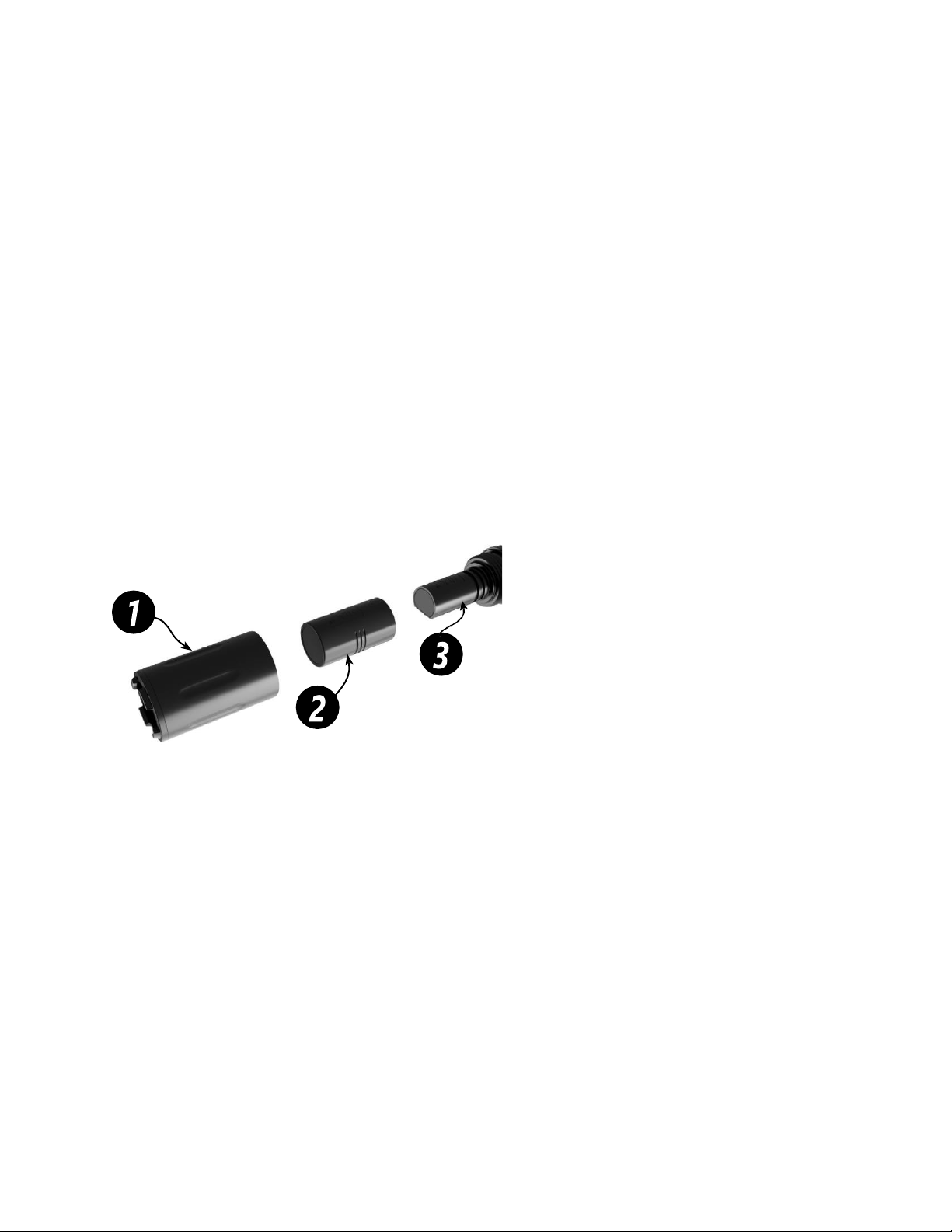
Your ODO-TX probeincludesthefollowingitems:
1
The sensor guard cap protects and seals the sensor cap in place.
2
The membrane sensor cap (AM-ODO-TX-CAP) has a luminescent foil that responds to oxygen
molecules. This cap needs to be replaced periodically; the typical life is two years.
3
The optical system contains the optics and circuitry that enable the sensor to calculate the
concentration of dissolved oxygen.

5
ODO-TX Operating Manual N116-155 rev 1.0
4.2. Specifications
Probe Parameters
Parameters
Optical Dissolved Oxygen Sensor
Data Transmission
Analog (4-20mA), RS485, Modbus
Range, DO
0-60 mg/L; 0-600% Saturation
Accuracy, DO
+/- 0.1 mg/L (0-20 mg/L)
+/-2% (20-60 mg/L)
Resolution, DO
0.01 mg/L
Response Time, Cap
T63<5s, T90<45s, T95<60s
Units, DO
mg/L, ppm, % saturation
Range, Temp.
-5°C to 50°C (23°F to 122°F)
Accuracy, Temp
+/- 0.1°C
Resolution, Temp
0.01°C
Units, Temp
Celsius, Fahrenheit
Salinity Compensation
Fixed or real-time capable
Barometric Compensation
Fixed or real-time capable
Methods
EPA-approved methods 1002-8-2009,
1003-8-2009, 1004-8-2009 Standard
Methods 4500-O
Calibration
1-2 points via RS485 Connection OR at
local controller
Calibration Time
~1 min (for each point)
Calibration Freq
1-2 years
Physical
Wetted Material
PVC Body, Cycoloy® (PC/ABS)1
Ryton® (PPS), PC/PMMA2
Reading Rate
1 second
Power Requirements
8 to 36 VDC
Power Consumption
Maximum (measurement): 50 mA at
12 VDC
Idle (communication only): 2 mA at 12
VDC
IP Rating
IP-67 with sensor cap off; IP-68 with
sensor cap installed
Compliance
EMC 2014/30/EU
IEC 61000-6-2:2005
EN 55011:2009
1
Cycoloy is a registered trademark of SABIC GLOBAL Technologies B.V.;
2
Ryton is a registered trademark of Solvay SA.

6
ODO-TX Operating Manual N116-155 rev 1.0
Environmental
Pressure
150 psi from 0° to 50°C
Depth
100 m (328 ft) @ 25°C
Operating Temperature (non-freezing)
-5°C to 50°C (23°F to 122°F)
Storage Temperature
-40°C to 65°C (-40°F to 149°F)
Interferences
Alcohols >5%; hydrogen peroxide > 3%;
sodium hypochlorite (commercial bleach)
> 3%; gaseous sulfur dioxide; gaseous
chlorine. Do not use in organic solvents
(e.g., acetone, chloroform, methylene
chloride, etc.), which may swell the
sensing element (foil matrix) and destroy
it.
4.3. Dimensions
4.4. Connections to power supply and controller
1) The two RS485 wires can be cut if the user does not need PC monitoring or firmware updates.
2) Power supply: 5-36VDC. Make sure to follow the wiring instructions above and provide the
proper power. Connecting the probe to any power outside the normal range may result in
damage and may void the warranty.
Wire color
Description
Red
Power (8~ 36 VDC)
Black
GND (ground is shared between the power input and signal output, please
make sure grounds are connected if external power supply is used)
Green
RS 485 B (+)
White
RS 485 A (-)
Blue
Analog Output 1 (configured using CommKit)
Yellow
Analog Output 2 (configured using CommKit)

7
ODO-TX Operating Manual N116-155 rev 1.0
5. Installation
The AM-ODO-TX can be connected to an AquaMetrix AM-2300 controller or any PLC. The probe can
output either a single output or dual outputs. As factory default, the ODO-TX comes wired as such:
Using the RS485 connection the user can change the default analog outputs from the following
selections: An optional configuration outputs the temperature or pressure as a second parameter. The
AM-2300 can connect up to 4 AM-ODOTX sensors without use of an external power supply.
An external power supply may be required if the PLC doesn’t have a 5-36VDC voltage source. The power
ground and signal grounds must be connected.
Refer to the instructions below, as well as the controller/analyzer manual for proper installation and
operation instructions.
Figure 1- Wiring AM-ODO-TX to an AM-2300 controller.

8
ODO-TX Operating Manual N116-155 rev 1.0
Figure 2- Wiring AM-ODO-TX to an AM-2252 or a PLC with an external power supply
6. Communication
6.1. Analog
The standard mapping for the ODO-TX analog output is:
Output
Output Parameter
4mA
20mA
Analog 1
Dissolved Oxygen (Percent Saturation)
0
200
Analog 2
Dissolved Oxygen (concentration)
0
20
The Two (2) Analog outputs can be remapped at the factory and by the customer
Output Parameter
Min
Max
Temperature
-5
50
Dissolved Oxygen (concentration)
0
60
Dissolved Oxygen (Percent Saturation)
0
600

9
ODO-TX Operating Manual N116-155 rev 1.0
6.2. Modbus
6.2.1. Common Registers
Register
Size
Mode & Access
Level (R/W)
Data Type
Description
9001
1
R/W
ushort
Device ID = 36 or 37
(analog model)
9002
2
R/W
ulong
Device serial number
9004
3
R/W
time
Manufacture date
6.2.2. Sensor Status Registers
Register
Size
Mode & Access
Level (R/W)
Data Type
Description
0005
3
R1
time
Cap start date/time 0
= no cap
0008
3
R1
time
Cap end of usable
life date/time 0 = no
cap
6.2.3. Device Specific Register 0042 Data Quality ID
Register 0042 is responsible for returning the various data quality IDs for the ODO-TX sensor. For a list of
the Data Quality IDs and definitions, see the Sensor Health Table in the Service and Troubleshooting
section of this manual.

10
ODO-TX Operating Manual N116-155 rev 1.0
6.2.4. Device Specific Registers
Register
Size
Mode & Access
Level (R/W)
Data Type
Description
Dissolved Oxygen Concentration
0038
2
R1
float
Measured value, Co
0040
1
R1
ushort
Parameter ID = 20
0041
1
R1/W2
ushort
Units ID
117 = mg/L (default)
118 = ug/L
0042
1
R1
ushort
Data quality ID (See
the Sensor Health
Table)
0043
2
R1/W3
float
Offline sentinel
value (default = 0.0)
0045
1
R1
16 bits
Available units =
0x0030 (48)

11
ODO-TX Operating Manual N116-155 rev 1.0
Temperature
0046
2
R1
float
Measured value
0048
1
R1
ushort
Parameter ID = 1
0049
1
R1/W2
ushort
Units ID
1= °C (default)
2= °F
0050
1
R1
ushort
Data quality ID
0051
2
R1/W3
float
Offline sentinel
value (default = 0.0)
0053
1
R1
16 bits
Available units =
0x00030 (3)
Dissolved Oxygen % Saturation
0054
2
R1
float
Measured value
0056
1
R1/W2
ushort
Parameter ID = 21
0057
1
R1/W2
ushort
Units ID
177 = percent
saturation (default)
0058
1
R1
ushort
Data quality ID
0059
2
R1/W3
float
Offline sentinel
value (default = 0.0)
0061
1
R1
16 bits
Available units =
0x0001 (1)

12
ODO-TX Operating Manual N116-155 rev 1.0
Oxygen Partial Pressure
0062
2
R1
float
Measured value
0064
1
R1
ushort
Parameter ID = 2
(pressure)
0065
1
R1/W2
ushort
Units ID
26 = torr (default)
0066
1
R1
ushort
Data quality ID
0067
2
R1/W3
float
Offline sentinel
value (default = 0.0)
0069
1
R1
16 bits
Available Units =
0x0200 (512)

13
ODO-TX Operating Manual N116-155 rev 1.0
6.2.5. Calibration Registers
Register
Size
Mode & Access
Level (R/W)
Data Type
Description
0118
2
R1/W3
float
Live salinity value
(PSU)
0120
2
R1/W3
float
Default salinity value
(PSU, default = 0.0)
0122
2
R1/W3
float
Live barometric
pressure (mbar)
0124
2
R1/W3
float
Default barometric
pressure (mbar,
default = 1013.25)
0126
2
R1/W3
float
100% saturation
calibration reading
(mg/L)
0128
2
R1/W3
float
100% saturation
temperature reading
(°C)

14
ODO-TX Operating Manual N116-155 rev 1.0
0130
2
R1/W3
float
100% saturation
salinity value (PSU)
0132
2
R1/W3
float
100% saturation
barometric pressure
(mbar)
0134
2
R1/W3
float
0% saturation
calibration reading
(mg/L)
0136
2
R1/W3
float
0% saturation
temperature reading
(°C)
0138
2
R1/W3
float
Calibration slope
(default = 1.0)
0140
2
R1/W3
float
Calibration offset
(default = 0.0)

15
ODO-TX Operating Manual N116-155 rev 1.0
6.2.6. Sensor Health Table
The instrument records a data quality ID between 0 and 7 with each reading. This ID indicates whether
errors occurred during the reading. It is stored in the instrument’s data quality register. See the table
below for details.
Abbreviation
Data Quality
ID
Text
Description
None
0
None
Normal Data Quality
Parameter measured without
errors using an expired user
calibration.
UC
1
User Cal Expired
Parameter measured without
errors using an expired
factory calibration.
FC
2
Factory Cal Expired
ERR
3
Unknown Error
Parameter measured with
error, sentinel value supplied.

16
ODO-TX Operating Manual N116-155 rev 1.0
WU
4
Sensor Warm-up
Sensor is warming up,
sentinel value supplied.
DIS
5
Sensor Warning
Parameter measured but does
not meet normal quality
criteria. The sensor has
sustained moderate damage,
or the recommended lifespan
has been reached.
CAL
6
Sensor Calibrating
Sensor is calibrating,
calibration value supplied.
OL
7
Sensor Missing
Sensor communication failed,
sentinel value supplied. Make
sure the sensor cap is
installed and properly seated.

17
ODO-TX Operating Manual N116-155 rev 1.0
7. Calibration
Connect the ODO-TX to a computer using the RS485 connection and open Commkit communication.
Alternately, connect the ODO-TX to an appropriate controller or PLC with calibration capability. If using
a PLC or controller to calibrate, refer to your controller manual. You can either perform a one-point or
two-point calibration as noted below.
7.1. One Point Calibration: Water-Saturated-Air 100% Saturation
1. Saturate a sponge with deionized water and insert it into the calibration cup.
2. Gently dry the probe and sensor cap with a paper towel. Make sure to remove all water and
debris.
3. Place the ODO-TX probe in the calibration cup so the sensor surface is about 2.5 cm (1”)
above the sponge.
4. Wait 5 to 10 minutes for temperature stabilization, but do not leave the probe in the
calibration cup for more than 30 minutes. Condensation can form on the sensor surface,
which may result in false readings after calibration. If condensation occurs, remove and
thoroughly dry the probe.
5. Once stable execute/complete single or first point calibration.
a. If using a PLC or controller to calibrate, refer to your controller manual.
7.2. Second Point (0%) of Two Point Calibration
1. Perform a one-point calibration as described above.
2. Remove the sponge from the calibration cup. Fill the cup to the fill line. This requires
approximately 10 mL of fresh sodium sulfite solution.
3. Place the instrument in the calibration cup. Leave at least 13 mm (1/2”) between the
surface of the sensing material and the bottom of the calibration cup.
4. Make sure the sensor is completely submerged in the solution.
5. Allow at least five minutes for the temperature to stabilize.
6. Once stable execute/complete second point calibration.
1. If using a PLC or controller to calibrate, refer to your controller manual.
7. After calibration, remove the probe. Detach the sensor. Thoroughly rinse the probe and
sensor to remove all sodium sulfite solution.
7.3. Temperature and Concentration (ppm or mg/l) calibration
Calibration for these parameters can be completed as a one or two-point calibration methpd on a
controller or PLC using respective reference meter.
Concentration calibration is automatically executed when calibrating the probe using Commkit
18
ODO-TX Operating Manual N116-155 rev 1.0
8. Maintenance
8.1. Cleaning
Probe maintenance includes cleaning the sensor cap, as well as the proper conditioning, preparation,
and storage of the test system. With the membrane sensor cap and guard cap installed on ODO-TX,
gently scrub the probe with a soft-bristled brush or nylon dish scrubber. Use Alconox or similar
cleaning solution to remove grease or other matter. Soak in vinegar and DI water to remove mineral
deposits or extensive fouling.
8.2. Replacing the Sensor Cap
The membrane Sensor Cap has a 2-year typical life after the sensor takes its first reading.
1. Remove the probe guard cap.
2. Use a lint-free cloth to remove any moisture from the probe.
3. Pull the used membrane sensor cap off of the sensor, without twisting.
4. Remove the existing O-rings from the sensor.
Do not touch orcleanthelens with anything other than the supplied lens wipe.
5. Use your finger to apply a very light layer of silicone-based lubricant around the O-ring
grooves.
6. Place the O-rings on the sensor. Apply another thin layer of lubricant to the O-rings and
grooves.
Note: Do not transfergreaseto the lens orsensorpins.
7. Remove the new cap from its sealed packaging and attach it to the sensor, being careful to
press firmly, without twisting, until it seals over the lens. Make sure that the O-rings are not
pinched or rolled between the cap and the sensor.
8. Replace the guard cap.
9. Each membrane cap comes factory calibrated, but for enhanced performance, perform a 1- or
2-point calibration to pair the new membrane sensor cap with the probe.
The ODO-TX series does consist of any user-serviceable parts. The membrane is a consumable item
and thus should only be replaced. If the guard Cap is damaged that should also be replaced. The
optical system can not be serviced and thus users/technicians must not attempt to open the probe
beyond removing the membrane sensor came and the guard cap.

19
ODO-TX Operating Manual N116-155 rev 1.0
9. Spare Parts
Part #
Description
AM-ODO-TX-CAP
ODO-TX-Replacement Sensor Cap
Sensor Cap Storage
Prior to installation—Store in factory supplied container.
Installed—Store in the calibration chamber with the storage cap attached and a few drops of
clean water.
10.Accessories
Part #
Description
AM-ODO-TX-CAL
Calibration Cap
AM-JB2
Junction box with integrated terminal strip
AM-HTA-R5
Ball Valve assembly for Hot-Tap insertion
AM-ARM-5
Submersion mounting kit
AM-TEE-R5
1” Union Tee with 3/4” adapter
AM-CFT-R5
Compression Fitting for 1” NPT sensors
AM-CBL
Extension cable
10.1. Calibration Cap
Calibrate the sensor with the Comm Kit Software or calibrate the sensor directly with your controller or
PLC.
1-Point Calibration
The optical Rugged Dissolved Oxygen sensor is very stable. The factory calibration should produce
readings within 3% accuracy. If you require readings with greater accuracy we recommend that you
perform a 1-point, 100% water-saturated air calibration as described below.
Water-Saturated Air
1. Remove the storage cap from the top of the calibration chamber and replace it with the vented
calibration cap.
1
2
Storage cap
Vented calibration cap

20
ODO-TX Operating Manual N116-155 rev 1.0
2. Place the sponge wafer in the bottom of the calibration chamber and saturate with
approximately 10 mL water.
3. Gently dry the instrument and sensing material with a paper towel, making sure there is no
water or debris on the instrument or on the sensing surface.
4. Place the instrument into the calibration chamber about 2.5 cm (1 in.) above the water-
saturated sponge.
5. Allow 5 to 10 minutes for temperature stabilization prior to starting the calibration procedure.
Do not leave the instrument in the calibration chamber for more than 30 minutes. This can allow
condensation to form on the sensing material, which will produce false low readings after
calibration. If condensation does occur, remove the instrument, dry the sensing material, place
the instrument in the chamber, and calibrate.
10.2. Mounting
10.2.1. General Installation Requirements
Check the probe to ensure that no air bubbles have formed on the electrodes during submersion.
10.2.2. Submersion Mounting with the AM-ARM-5
The ODO-TX is a fully submersible sensor. Although not required, submersion hardware to protect the
cable from wear and tear is advisable. The AM-ARM-5 consists of a 4-foot long CPVC pipe with a 1” FNPT
fitting on the front end on which to mount the probe and a strain relief on the back end. A wire bracket,
constructed of thick aluminum wire, is used to secure the arm onto the edge of a tank or basin.
Table of contents
Other Water Analytics Measuring Instrument manuals


Popular Measuring Instrument manuals by other brands

Powerfix Profi
Powerfix Profi 278296 Operation and safety notes

Test Equipment Depot
Test Equipment Depot GVT-427B user manual

Fieldpiece
Fieldpiece ACH Operator's manual

FLYSURFER
FLYSURFER VIRON3 user manual

GMW
GMW TG uni 1 operating manual

Downeaster
Downeaster Wind & Weather Medallion Series instruction manual

Hanna Instruments
Hanna Instruments HI96725C instruction manual

Nokeval
Nokeval KMR260 quick guide

HOKUYO AUTOMATIC
HOKUYO AUTOMATIC UBG-05LN instruction manual

Fluke
Fluke 96000 Series Operator's manual

Test Products International
Test Products International SP565 user manual

General Sleep
General Sleep Zmachine Insight+ DT-200 Service manual


