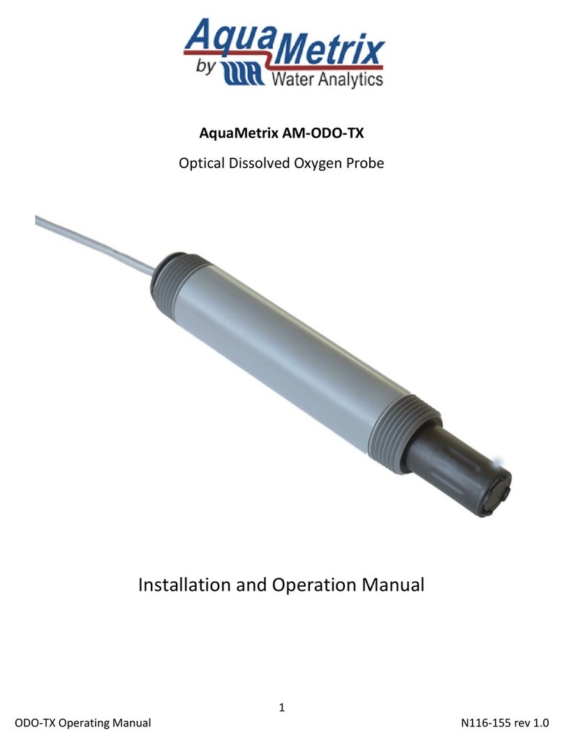
Water Analytics AquaMetrix AM-FOG User manual

N116-152 AM-FOG
Version 0.9 / 9-15-21
AM-FOG
Portable FOG Analyzer

2
AM-FOG Operating Manual rev 0.9
Installation and Operation Manual
Contents
1Introduction............................................................................................................................................3
2Specifications..........................................................................................................................................3
3Principle of Operation ............................................................................................................................4
4What Comes with the AM-FOG Probe....................................................................................................4
5Operating the AM-FOG Probe ................................................................................................................4
Downloading the AM-FOG Connect App ......................................................................................4
Getting Going ................................................................................................................................5
Configuring the Probe...................................................................................................................6
Calibration.....................................................................................................................................6
6Taking a Measurement...........................................................................................................................7
Basic Measurement with the Measure Screen.............................................................................7
Diagnostics ....................................................................................................................................8
7Troubleshooting .....................................................................................................................................8

3
AM-FOG Operating Manual rev 0.9
1Introduction
The AM-FOG analyzer is the first probe to replace core samplers (e.g. Sludge Judge, Dipstick Pro) with a
digital version that is portable, robust, customizable and inexpensive. It measures the level of fats, oils,
and grease (FOG) in grease interceptors quickly, accurately and as cleanly as possible. The probe is the
result of five years of intense product development. The probe is aimed primarily at inspectors of
Authorities Having Jurisdiction (AHJ, aka municipalities) but interceptor service companies (“haulers”)
and food service establishment (FSE) operators will also find the AM-FOG probe to be an important part
of their operation.
Competing FOG analyzers have relied on conductance, which suffers from fouling or ultrasonic
transducers, which also are impacted by fouling and are very expensive to build. Because it is based on
measuring the electrical properties of the surrounding medium there are no moving parts or expensive
transducers. Coating of the probe changes the reading very slightly, so fouling is not a major problem.
The result is a probe that can withstand the extreme physical and chemical environment of a grease
interceptor. There are other FOG analyzers that use capacitance, but the AM-FOG uses several ingenious
innovations which make the probe robust, inexpensive, and extremely easy to use.
The length of the AM-FOG probe can be made to any multiple of 8 inches so that it can be configured for
any grease interceptor size. The embedded firmware senses the correct length and customizes the user
interface on the cell phone app for any probe.
2Specifications
Detection
Water, FOG, air, sludge
Data
Transmission
Adjustable from 1 to 60 min.
Resolution
2.5 cm (1”)
Wireless
transmission
Bluetooth Low Energy (BLE)
Measurement
Length
12” to 72” in 6” increments
Transmission
Range
>100 m
Alarm Levels
Customized. Default—25%
Rule
Status Indicztor
LED: Green / Red
Calibration
One-button—in water
Operation Modes
Calibrate, Run, Battery check
Wetted
Materials
PVC, polycarbonate
Batttery
Lithium ion, rechargeable
Mounting
Bracket
Temperature
-10 to 60 °C
Extension
1 to 6 ft. At
pH Range
2 to 12
Cleaning
Circular wiper
Ingress
NEMA 6P

4
AM-FOG Operating Manual rev 0.9
3Principle of Operation
As stated in the introduction, the AM-FOG analyzer works by measuring the capacitance of the
surrounding medium. The capacitance is related to an electrical property called the dielectric constant.
Materials that hold a large charge, such as air, have a high dielectric constant. Those that can’t, such as
water, have a low dielectric constant. In general, insulators have high dielectric constants whereas
conductors have very low constants. Grease, or FOG, has a relatively high dielectric constant though not
as high as air.
The AM-FOG analyzer uses electrodes whose electric fields extend several centimeters into the medium.
Therefore, a coating of grease on the surface of the probe has a minimal effect on the measurement of
the capacitance. The probe consists of a number (1 to 8) 8” sensor boards attached in series, with each
board containing 8 capacitance sensing elements located at 1” intervals. Therefore, the probe length can
be anywhere from 8” to 64”, with 1” resolution, regardless of size. The probe can be used in nearly all
hydromechanical interceptors and all but the largest gravity interceptors.
Firmware inside the probe communicates via Low Energy Bluetooth (BLE) to an app smart device such as
a cell phone or tablet. There is an app for both Android and iOS (iPhone) devices. Configuration,
calibration, and measurement are all done on the app.
The value of the capacitance that the probe reads is in units of frequency (Hz). Values range from about
60,000 in water to about 80,000 Hz in air. To make the user interface easier to understand the value of
the sensors in water are set to zero and the value of the sensors in air are set to 10,000. Typical FOG
values then fall into the range of 6000 to 8000.
Since each sensing element is slightly different from all others the probe must be corrected such that all
sensors give approximately the same value of 0 to 10,000 when immersed in the same medium. During
the process of calibration, the probe is immersed in water and the app assigns zero to all sensor
elements. The user then hangs the probe in air and the calibration routine assigns 10,000 to all sensor
elements. Of course these values drift by as much as 10% over several days of use so calibration must be
done on a periodic basis—approximately weekly.
4What Comes with the AM-FOG Probe
The AM-FOG probe is a self-contained unit and has no accessories that are necessary for operation. The
only other component needed is the free app loaded onto your smart phone. The handle of the probe
will enable you to immerse the probe in the interceptor. If you need to access an interceptor that is more
than about two feet underground, you will need an extension pole with a grabber. Here is an example:
Unger 42.5 in. Steel-Rubber Rugged Trash Reacher Grabber-971340 - The Home Depot.
The probe comes with a 3” diameter PVC carrying case. The carrying case doubles as a container for
calibrating the probe in water. Simply stand the case up and fill it with water such that the level reaches
the top when the probe is fully inserted.
5Operating the AM-FOG Probe
Downloading the AM-FOG Connect App
The interface to the probe is through an app on an Android or iOS (Apple) phone. The app is free. We are
constantly adding useful features so keep checking the app store for the latest version. (Will the app
notify the user that a new version is available and automatically install it?)

5
AM-FOG Operating Manual rev 0.9
For an Android phone go to the Play Store and look for AM-FOG. For an iPhone go to the App Store.
The app does NOT connect to the internet. Therefore, it collects NO information from you to send to us
so you can rest assured that there is no downside to loading it onto your device.
Getting Going
1. Turn on the probe by pressing the power
button. The green LED surrounding it will blink.
If nothing happens then it’s possible that the
battery came loose during shipment. If you
open the cover of the head enclosure you will
see the battery and its connector.
2. Launch the app. Just press the AM-FOG
Connect app icon.
3. Press the SCAN button on the bottom of the
initial screen. It and will search for the
Bluetooth signal from the probe.
4. Press Yes to grant permission to connect to the
probe. This allows your device to communicate
to the probe via Bluetooth (BLE). If the probe
does not connect after several minutes, it will
go to sleep and you will need to scan for the probe again.
5. When the app finds the probe, a new screen will display a line item containing the probe’s MAC
address. In the screenshot shown on the right the address is E8:9C:C2:98:D5:E3. Every probe has a
unique MAC address. A good practice is to write the address, or the last 4 characters, on the outside
of the probe.
6. If there is more than one probe powered on the screen will list all those probes.
7. Click on the probe from the list (likely the only probe on the list). You will see a circulating Connecting
icon. If the Connecting icon continues ad infinitum, then you waited too
long and the probe timed out. Just restart the connection process. If the
Connecting icon continues to spin, then the controller board in the head of
the probe has lost contact with the sensor boards in the probe. The likely
cause is that the ribbon cable that connects the controller board to the top
sensor board has disconnected.
8. Upon successful connection the Configuration screen will appear.

6
AM-FOG Operating Manual rev 0.9
Configuring the Probe
Successful connection with the probe automatically brings up the Configuration
screen. There are four functions in the app: Measure, Diagnostics, Calibrate and
Configuration. They are accessed by clicking on the menu icon in the upper left
corner. The menu icon appears for the first time when the Configuration screen
appears.
The top of the Configuration screen allows you to personalize the probe. The
bottom of the screen allows you to set the range values for the app to be distinguish
FOG from water, FOG from air and water from sludge. There should be default
values already loaded in. They are;
1. Sludge: 0-100
2. Water: 101-1000
3. FOG: 1001-7000
4. Air: > 7001 (automatically set from the FOG upper value)
5. Temperature Compensation: 71.0
If you change the values, you must enter numbers that follow the order of
Air>FOG>Water>Sludge. If you don’t, you will get an error message.
(9-14-21: NOTE: The sludge range should be higher than the water range. Also the
sludge range does nothing. This will be fixed.)
NOTE: As of this date, the probe cannot reliably distinguish water from sludge. This
will likely change in the future. To eliminate the sludge reading it is set for the very
narrow range of 0 to 100. If the probe reading yields values between 0 and 100 then
either recalibrate the Please note that the range for sludge is very narrow. That’s
because we don’t yet have a solid understanding of solids, so we do our best to bury
this measurement (for now!).
There is one more parameter in the bottom screen—the temperature coefficient.
This parameter adjusts the frequency values for changes resulting from different
temperatures. We have found that -71 Hz/°C is the best fit value, and it is unlikely
that you will ever change it.
Calibration
As with any sensor, two points are required to calibrate the FOG probe. The firmware
converts the frequency values from the sensors into arbitrary values, such that 0
represents the lowest value—water—and 10,000 represents the highest—air.
Calibrating the probe in water requires a container at least as deep as the probe. The 3”
diameter carrying case doubles as a reservoir for water calibration. A wider container
will give slightly better accuracy. If you have several probes in use, then a 4” PVC tube
capped at the bottom and fixed to the wall gives better accuracy and is easier to use.
For air calibration hanging the probe in air is sufficient. Keep the probe at least 2” away
from any surface.

7
AM-FOG Operating Manual rev 0.9
To calibrate the probe, press the menu icon in the top left and bring up the menu screen
(right). Select Calibrate.
Follow the instructions:
1. Immerse the probe in a bath of water up to the top of the PVC pipe. (Do NOT
immerse the head unit.) We use a 3” PVC pipe capped at the bottom, and we will
provide such a unit for sale.
2. Allow about a minute for the probe to equilibrate in water.
3. Press the Water Calibration button.
4. When the Alert window appears select Calibrate. This starts the one-minute
calibration.
5. The Calibration screen will return.
6. Hang the probe in the air for at least one minute to let the probe equilibrate.
7. Press the Air Calibration button.
8. When the Alert window appears select Calibrate. This starts the one-minute
calibration.
9. The Calibration screen will return.
Note that the Calibration screen reports the results of the calibration: the date of both calibrations and
the slope and the intercept of the graph that converts frequency values to the calibrated range of 0 to
10,000.
6Taking a Measurement
Basic Measurement with the Measure Screen
Once the configuration is set you are ready to take measurements. The screen
that you, as a ordinary user, will use on a daily basis is the Measure screen.
This is simply a bar screen that is color coded: Dark blue is water, light blue is
air, orange is FOG and brown is sludge. (Because sludge is not yet operational
the default range in the Configuration screen should prevent it from appearing
in measurements.)
Try holding your hand around the middle of the probe. Your hand has
approximately the same dielectric constant as FOG so the part of the probe
surrounded by your hand will turn orange. It will take a full minute to
equilibrate and settle into a light blue bar with an orange bar in the middle.
Next, try sticking the probe in water and watch the bottom part of the probe
in water turn dark blue. Notice that the percentage of air, FOG, water and
sludge appears to the right of the bar graph.
Note also that the app determines the top of the liquid level of the
interceptor. It does this by determining the lowest level of the air column. The
app uses the top of the trap to calculate composition percentages with
respect to the liquid volume. A red triangle appears more than 25% of the
volume of the interceptor is occupied by FOG (plus sludge when available).

8
AM-FOG Operating Manual rev 0.9
Diagnostics
For routine measurements the Measure screen is sufficient. To view the
actual measurements that go into the Measure screen the Diagnostics screen
is invaluable, especially for troubleshooting and for setting values in the
Configuration screen.
With the measure screen open, click on the little waveform icon on the upper
right of the Measure screen or select Diagnostics from the menu icon in the
upper left. This will bring you to the Diagnostics screen. For the screenshot on
the right the probe is 16” with 16 elements. The same color coding applies to
the Diagnostics screen but with the addition of sensor elements, height from
the bottom sensor and the values of each element—actual frequency and
scaled frequency (0 to 10,000).
Immersing the probe in an actual interceptor or a container with water and
oil will show a screen like the one on the right.
7Troubleshooting
As with any sophisticated electronic device undergoing beta testing,
issues arise that need to be improved. The major hardware issue that
we have discovered is that the ribbon cable that connects the
electronic guts of the probe to the controller in the black enclosure
can come loose with rough handling. If the probe connects but
doesn’t show a bar graph like in the figures above it’s a 20:1 bet that
the ribbon cable came loose.
Simply unscrew the top of the enclosure. The ribbon cable slips over
the connector on the board such
that the one gray conductor
connects to the Power pin. See
picture below. It’s possible, but unlikely, that the ribbon disconnects
from the other end that connects to the sensors in the probe.
Reattach as shown in the picture below.
If problems persist contact us at support@wateranalytics.net or call us at 978-749-994.
Table of contents
Other Water Analytics Measuring Instrument manuals
