Water Furnace SPECTRA SX Series User manual

SX Series
3/4 through 6 ton Commercial
and Residential Geothermal
System Installation Instructions
Installation and servicing of air conditioning equipment can be hazardous due to system
pressure and electrical components. Only trained and qualified service personnel should install,
repair or service air conditioning equipment.
Untrained personnel can perform basic maintenance functions of cleaning coils and cleaning
and replacing filters. All other operations should be performed by trained service personnel. When
working on air conditioning equipment, observe precautions in the literature, tags and labels
attached to the unit and other safety precautions that may apply.
Follow all safety codes. Wear safety glasses and work gloves. Use quenching cloth for brazing
operations. Have fire extinguisher available for all brazing operations.
WARNING: Before performing service or maintenance operations on system, turn off
main power switches to indoor unit. Turn off accessory heater power switch if applicable.
Electrical shock could cause personal injury.
Move units in the normal “up” orientation as indicated by the arrows on each carton. Horizontal
units may be moved and stored per the information on the carton, “Do not stack more than 3 units
in total height.” Vertical units are not to be moved, but may be stored one upon another at a
maximum height of 2 units. When the equipment is received, all items should be carefully checked
against the bill of lading to be sure all crates and cartons have been received. Examine units for
shipping damage, removing the units from the cartons if necessary. Units in question should also
be internally inspected. If any damage is noted, the carrier should make the proper notation on the
delivery receipt, acknowledging the damage.
P/N 96P537A01 rev. 4/99
Installation
Guide
Safety
Considerations
Moving and
Storage
Model
Nomenclature
Table of
Contents Initial Desuperheater Start Up 11
Electrical Connections 11-12
Unit Electrical Data 13
Unit Operating Pressures 13
Wiring Schematic 14-15
Thermostat 16
Blower Performance Data 16
Unit Start Up 17-18
Preventive Maintenance 18-19
Troubleshooting 19
Replacement Procedures 19
Model Nomenclature 1
Safety Considerations 1
Moving and Storage 1
Physical Data 2
General Installation Information 2-5
Boiler/Cooling Tower Closed Loop Systems 5
General Piping 6
System Cleaning and Flushing 6-7
Ground Source Closed Loop Systems 7-8
Open Loop Ground Water Systems 8-9
Desuperheater Connection 9-11
0X0TSXV
Unit Size
036 = 36,000 BTUH Nominal cooling
at 85°F entering water
Electrical Characteristics
0 = 208-230/60/1 Commercial
1 = 208-230/60/1 Residential
2 = 265-277/60/1 Commercial
3 = 208-230/60/3 Commercial
4 = 460-480/60/3 Commercial
5 = 575-600/60/3 Commercial
Design Vintage
Model Type
SXV = Vertical Unit
SXH = Horizontal Unit
036 C C1
Coax Options
C = Copper
N = Cupronickel
Non-Standard Options
Discharge Air Options
T = Top (Vertical)
E = End (Horizontal)
S = Side (Horizontal)
L
Return Air Options
L = Left return
R = Right return
B = Commercial Microprocessor Unit Controls
C = ElectroMechanical Unit Controls
Hot Water Options
0 = None
1 = Hot Water Generation W/Pump (Residential)
2 = Hot Water Generation Without/Pump (Commercial)
Cabinet
0 = Painted Steel Cabinet
1 =Galvanized Steel Cabinet

2
SPECTRA COMMERCIAL AND RESIDENTIAL INSTALLATION GUIDE
Unit Location
Locate the unit in an indoor area that allows easy removal of the filter and access
panels, and has enough space for service personnel to perform maintenance or repair.
Provide sufficient room to make water, electrical and duct connection(s). If the unit is
located in a confined space, such as a closet, provisions must be made for return air to
freely enter the space by means of a louvered door, etc. Any access panel screws that
would be difficult to remove after the unit is installed should be removed prior to setting the
unit. On horizontal units, allow adequate room below the unit for a condensate drain trap
and do not locate the unit above supply piping. These units are not approved for outdoor
installation and must be installed inside the structure being conditioned.
CAUTION:
Do not locate in areas where ambient conditions are not maintained
within 45
°
-95
°
F and up to 75% relative humidity.
Setting the Vertical Units
Vertical units are available in left or right air return configurations. Top flow vertical units
should be mounted level on a vibration absorbing pad slightly larger than the base to
provide isolation between the unit and the floor. It is not necessary to anchor the unit to the
floor (see figure 1). Bottom flow units
should be mounted level and sealed
well to floor to prevent air leakage.
If left side unit access will be
limited after installation, remove the
two left side control box mounting
screws before setting the unit (leave
the two front mounting screws intact).
This will allow the control box to be
removed with only the two front
mounting screws for future service.
Setting the Horizontal Units
Horizontal units are available with side or end discharge and may be field converted
from one to the other by replacing the discharge panel. The new panel must be ordered.
Horizontal units are normally suspended from a ceiling by four 3/8” diameter threaded rods
(6 on SXH042-068). The rods are usually attached to the unit corners by hanger bracket
kits furnished with each unit.
Figure 1– Vertical Unit Mounting
General
Installation
Information
Physical
Data
MODEL SX010 SX013 SX016 SX019 SX024 SX030 SX036 SX042 SX048 SX058 SX068
Fan Wheel 6 X 8 6 X 8 9 X 7 9 X 7 9 X 7 9 X 7 9 X 7 10 X 10 10 X 10 11 X 10 11 X 10
PSC Fan Motor HP - # of Speeds 1/10 - 4 1/10 - 4 1/6 - 3 1/6 - 3 1/5 - 3 1/3 - 3 1/2 - 3 1/2 - 3 1/2 - 3 3/4 - 3 1.0 - 3
Compressor Rotary Rotary Rotary Rotary Recip Recip Recip Recip Recip Scroll Scroll
R22 (oz.) 28.0 36.0 38.0 43.0 63.0 66.0 65.0 95.0 86.0 98.0 98.0
Vertical
Air Coil Dimensions (in.) 12 x 16 16 x 16 19 x 20 19 x 20 24 x 20 24 x 20 27 x 20 28 x 25 28 x 25 32 x 25 36 x 25
Air Coil Face Area (sq ft.) 1.3 1.8 2.6 2.6 3.3 3.3 3.8 4.9 4.9 5.6 6.3
Air Coil # of Rows 3 3 3 3 3 3 3333 3
Filter - 1" Throwaway (Std.) 16 X 20 16 X 20 18 X 24 18 X 24 24 X 24 24 X 24 2-14 X 24 2 -14 X 30 2 - 14 X 3
0
2 - 10 X 30 3 - 12 X 30
1 - 12 X 30
Filter - 1" Electrostatic (opt.) EAF1620 EAF1620 EAF1824 EAF1824 EAF2424 EAF2424 EAF2428 EAF2830 EAF2830 EAF3032 EAF3036
Weight 150 163 180 183 265 270 290 326 344 401 428
Horizontal
Air Coil Dimensions (in.) 12 x 16 16 x 16 18 x 21 18 x 21 18 x 27 18 x 27 18 x 30 20 x 35 20 x 35 20 x 40 20 x 45
Air Coil Face Area (sq in.) 1.3 1.8 2.6 2.6 3.4 3.4 3.8 4.9 4.9 5.6 6.3
Air Coil # of Rows 3 3 3 3 3 3 3333 3
Filter - 1" Throwaway (Std.) 16 x 20 16 x 20 18 x 24 18 x 24 2-18 x 18 2-18 x 18 2-18 x 18 1 - 20 x 12 1 - 20 x 12 1 - 18 x 20 2 - 24 x 20
1 - 20 x 25 1 - 20 x 25 1 - 24 x 20
Filter - 1" Electrostatic (opt.) EAF1620 EAF1620 EAF1824 EAF1824 EAF1836 EAF1836 EAF1836 EAF2037 EAF2037 EAF2042 EAF2048
Weight 155 164 194 204 270 272 286 343 347 431 458
Vibration
Absorbing
Mesh
Air
Pad

3
SPECTRA COMMERCIAL AND RESIDENTIAL INSTALLATION GUIDE
CAUTION: Do not use rods smaller than 3/8” diameter since they may not be
strong enough to support the unit. The rods must be securely anchored to the ceiling.
Lay out the threaded rods per the dimensions in Figure 2A, and assemble the hangers to
the unit as shown. Securely tighten the brackets to the unit using the weldnuts located on the
underside of the bottom panel. When attaching the hanger rods to the bracket, a double nut
is required since vibration could loosen a single nut. The unit should be pitched approxi-
mately 1/4” towards the drain in both directions, to facilitate condensate removal (see Figure
3B, on page 4). Use only the bolts provided in the kit. The use of longer bolts could damage
internal parts.
Some residential applications require an attic floor installation of horizontal units. In this
case, the unit is set in a full size secondary drain pan on top of vibration absorbing mesh.
The secondary drain pan prevents possible condensate overflow or water leakage damage to
the ceiling. The secondary drain pan is usually placed on a plywood base isolated from the
ceiling joists by additional layers of vibration absorbing mesh.
Duct System
An air outlet collar is provided on vertical top flow units and all horizontal units to facilitate
a duct connection (vertical bottom flow units have no collar). A flexible connector is recom-
mended for discharge and return air duct connections on metal duct systems. Uninsulated
duct should be insulated with a minimum of one-inch duct insulation. Application of the unit to
uninsulated ductwork in an unconditioned space is not recommended as the unit’s perfor-
mance will be adversely affected.
Air Handler
Section
Compressor
Section
Figure 2A– Hanger Location and Assembly
Bolt and
Lockwasher
Vibrator
Isolator
Washer
Hex Nuts
(by others)
3/8" Threaded Rod
(by others)
MODEL
MODEL A B C D E
SXH010-013 24.75 42.5 22.5 44 -
SXH016-019 24.75 51.5 22.5 53 -
SXH022-034 24.75 61.5 22.5 63 -
SXH042-048 27.75 70.5 25.5 72 29.87
SXH058 27.75 75.5 25.5 77 29.87
SXH068 27.75 80.5 25.5 82 29.87
Figure 2B– Optional Filter Rack
1" duct connection provided
Air tight construction
MODEL A B C D E MODEL NO.
SX010-013 20.2 16.2 1.8 0.5 5.5 DCH1620
SX016-019 24.2 18.2 1.2 0.5 5.5 DCH1824
SX024-030 36.2 18.2 1.2 0.5 5.5 DCH1836
SX042-048 37.2 20.2 1.8 0.5 5.5 DCH2037
SX058 42.2 20.2 1.8 0.5 5.5 DCH2042
SX068 48.2 20.2 1.3 0.5 5.5 DCH2048

4
SPECTRA COMMERCIAL AND RESIDENTIAL INSTALLATION GUIDE
For vertical bottom flow units, cut the air discharge floor opening at least 1/2" larger than
unit air outlet.
Protect opening edges in combustible flooring with sheet metal overwrap.
Discharge air only into a suitable supply duct system and do not locate registers or open-
ings directly under unit air outlet.
If the unit is connected to existing ductwork, a previous check should have been made
to assure that the duct has the capacity to handle the air required for the unit application. If
ducting is too small, as in the replacement of heating only systems, larger ductwork should
be installed. All existing ductwork should be checked for leaks and repairs.
The duct system should be sized to handle the design airflow quietly.
To maximize
sound attenuation of the unit blower, the supply and return plenums should include internal
duct liner of glass fiber or be of ductboard construction for the first few feet.
If air noise or
excessive air flow is a problem, the blower speed can be changed. See the Blower Perfor-
mance and Fan Speed sections for further instructions.
CAUTION:
Be sure to remove the foam shipping material from the blower throat
before connecting ductwork.
Water Piping
All Residential Spectra source
water connections are swivel piping
fittings that accept a 1" Male Pipe
Thread (MPT) (see Figure 4A). The
swivel connector has a rubber gasket
seal similar to a garden hose gasket,
which when mated to the flush end of
any 1" threaded pipe provides a leak-
free seal without the need for thread
sealing tape or compound. Check to
insure that the rubber seal is in the
swivel connector prior to attempting
any connection. The rubber seals are
shipped attached to one of the swivel
connections on the unit. DO NOT
OVERTIGHTEN or leaks may occur.
To make the connection to a
ground loop system, mate the brass
connector (supplied in CK4L & CK4S
connector kits) against the rubber
gasket in the swivel connector, and
thread the female locking ring onto
the pipe threads, while maintaining
the brass connector in the desired
direction (see Figure 4B). Tighten the
connectors by hand to provide a leak
proof joint. When connecting to an
open loop (ground water) system,
thread any 1" MPT fitting (PVC or
copper) into the swivel connector and
tighten in the same manner as noted
above. The open and closed loop
piping system should include pressure/temperature taps for serviceability.
Figure 3A - Horizontal Drain Connection
1/4” Pitch
Drain
Figure 3B - Uni Pitch for Drain
Figure 4B - The
Female Locking Ring is
threaded onto the pipe
threads which holds the
male pipe end against
the gasket, and seals
the joint. HAND
TIGHTEN ONLY! DO
NOT OVERTIGHTEN!
Figure 4A
This side is soldered
to the unit tubing
Brass Body
Threaded Female
Locking Ring Retaining Ring
Gasket Seal
Brass Stop Ring
1.5" 1.5"
Vent (if needed)
3/4" PVC
3/4" barb to
glue adapter *
1/8" per foot
Clear PVC hose *
Plastic Hose Clamp *
Copper tube stub
*Included with unit

5
SPECTRA COMMERCIAL AND RESIDENTIAL INSTALLATION GUIDE
Never use flexible hoses smaller than 1" inside diameter on the unit and limit hose
length to 10 ft. per connection. Check carefully for water leaks.
Water Quality
The unit may be ordered with either a copper or a cupronickel coaxial heat exchanger.
Copper is adequate for closed loop and open loop ground water systems which are not high
in mineral content. In conditions anticipating moderate scale formation or in brackish water,
a cupronickel heat exchanger is recommended. In ground water situations where scaling
could be heavy or where biological growth such as iron bacteria will be present, a closed
loop system is recommended. Ground water unit heat exchanger coils may over a period of
time lose heat exchange capabilities due to a buildup of mineral deposits inside. These can
be cleaned, but only by a qualified service mechanic as special solutions and pumping
equipment are required. Desuperheater coils can likewise become scaled and possibly
plugged. In areas with extremely hard water, the homeowner should be informed that the
heat exchanger may require occasional acid flushing.
Freeze Protection (Commercial Microprocessor Only)
Set the freeze protection switch SW1 #2 on the microprocessor board for applications
using a closed loop antifreeze solution to" LOOP". On applications using an open loop/
ground water system or non freeze protected loop, set to "WELL" (the factory setting).
Condensate Drain
On vertical units, the internal condensate drain assembly consists of a drain tube which
is connected to the drain pan, a 3/4" PVC female adapter and a flexible connecting hose.
The female adapter may exit either the front or the side of the cabinet. The adapter should
be glued to the field-installed PVC condensate piping. On vertical units, a condensate hose
is inside all cabinets as a trapping loop; therefore, an external trap is not necessary. On
horizontal units, a copper stub is provided for condensate drain piping connection. An
external trap is required (see Figure 3A page 4). If a vent is necessary, an open stand pipe
may be applied to a tee in the field-installed condensate piping.
Air Coil
To obtain maximum performance the air coil should be cleaned before start up. A 10%
solution of dishwasher detergent and 90% water is recommended for both sides of coil. A
thorough water rinse should follow.
Boiler/Cooling Tower
The water loop is usually maintained between 60°F and 90°F (Spectra units allow 25°F -
110°F EWT) for proper heating and cooling operation. see Figure 5 page 6 for a typical
installation.
To reject excess heat from the water loop, the use of a closed circuit evaporative cooler
or an open type cooling tower with a secondary heat exchanger between the tower and the
water loop is recommended. If an open type cooling tower is used without a secondary heat
exchanger, continuous chemical treatment and filtering of the water must be performed to
ensure the water is free from damaging materials.
CAUTION: Water piping exposed to outside temperatures may be subject to freezing.
NOTE:
For Boiler/Cooling Tower Systems with no antifreeze solution, set SW1-Switch
#4 to the "WELL" position.
Boiler/Cooling
Tower Closed
Loop Systems

6
SPECTRA COMMERCIAL AND RESIDENTIAL INSTALLATION GUIDE
Figure 5- Closed Loop Cooler/Boiler System
Disconnects
Boiler/Cooling
Tower Loop
Flexible Duct
Collar
3/8”
Threaded rods
(6) on AT040-046
Hanging
Brackets
(included)
P/T Plugs
Line Voltage
To Thermostat
Insulate supply
plenum and use at
least a 90°elbow
to reduce noise Hose Kits
To Line
Power
Electric heat
assembly
(optional)
Drain per
Figure 2 On air
coil, side or end Drain per
Figure 2
Water Piping Connections
Units should not be connected to the supply and return piping until the water system
has been cleaned and flushed completely. Supply and return water connections are
standard female pipe thread. Never use flexible hoses with an inside pipe diameter that is
smaller than the water connections on the unit and limit the hose length to 10 feet or less
per connection. High-pressure flexible hoses provide sound attenuation for both normal unit
operating noise and hydraulic pumping noise. Hard piping can also be brought directly
to the unit although it is not recommended since no vibration or noise attenuation can
be accomplished.
Cleaning and Flushing
Prior to start up of any heat pump, the water circulating system must be cleaned and
flushed of all dirt and debris.
If the system is equipped with water shutoff valves, the supply and return runouts must
be connected together at each unit location (This will prevent the introduction of dirt into the
unit, see Figure 6). The system should be filled at the water make-up connection with all
air vents open. After filling, vents should be
closed.
The contractor should start the main
circulator with the pressure reducing valve
makeup open. Vents should be checked in
sequence to bleed off any trapped air and to
verify circulation through all components of the
system.
As water circulates through the system,
the contractor should check and repair any
leaks found in the piping system. Drain(s) at
the lowest point(s) in the system should be
opened for initial flush and blowdown, making
sure water fill valves are set at the same rate.
General
Piping
System
Cleaning
and Flushing
Figure 6 - Flushing with Water Shutoff
Valve Equipped Systems

7
SPECTRA COMMERCIAL AND RESIDENTIAL INSTALLATION GUIDE
Ground
Source Closed
Loop Systems
Check the pressure gauge at the pump suction and manually adjust the make-up water
valve to hold the same positive pressure both before and after opening the drain valves.
Flushing should continue for at least two hours, or longer if required, until drain water is
clean and clear.
The supplemental heater and/or circulator pump, if used, should be shut off. All drains
and vents should be opened to completely drain the system. Short-circuited supply and
return runouts should now be connected to the unit supply and return connections.
Refill the system with clean water. Test the system water for acidity and treat as
required to leave the water slightly alkaline (pH 7.5 to 8.5). The specified percentage of
antifreeze may also be added at this time. Use commercial grade antifreeze designed for
HVAC systems only. WaterFurnace recommends the Environol™ brand antifreeze.
Once the system has been filled with clean water and antifreeze (if used), precautions
should be taken to protect the system from dirty water conditions. Dirty water will result in
system-wide degradation of performance, and solids may clog valves, strainers, flow
regulators, etc. Additionally, the heat exchanger may become clogged which reduces
compressor service life and can cause premature unit failure.
In boiler/tower applications, set the loop control panel set points to desired tempera-
tures. Supply power to all motors and start the circulating pumps. After full flow has been
established through all components including the heat rejector (regardless of season), air
vented and loop temperatures stabilized, each of the units will be ready for check, test
and start up and for air and water balancing. Use form WFS159 and when performing
commercial check, test and start up. Obtain these forms from your commercial
representative or contact WaterFurnace.
Ground Source Systems
Once piping is completed between the unit, flow center and the ground loop (Figure 7
on page 8), final purging and charging of the loop is needed. A WaterFurnace flush cart (at
least a 1.5 hp pump) is needed to achieve adequate flow velocity in the loop to purge air
and dirt particles from the loop itself. Antifreeze solution is used in most areas to prevent
freezing. Flush the system adequately to remove as much air as possible, then pressurize
the loop to a static pressure of 40-60 psi. This is normally adequate for good system
operation. Loop static pressure may decrease soon after initial installation due to pipe
expansion and loop temperature change. Running the unit for at least 30 minutes after the
system has been completely purged of air will allow for this “break-in” period. It may be
necessary to adjust static pressure (by adding water) after the unit has run for the first time.
Loop static pressure will also fluctuate with the seasons. Pressures will be higher in the
winter months than during the cooling season. This fluctuation is normal and should be
considered when charging the system initially. Pressurizing the system to 40-60 psi in the
winter may result in a 15-20 psi static pressure in the summer.
After pressurization, be sure to remove the plug in the end of the loop pump motor(s) to
allow trapped air to be discharged and to insure the motor housing has been flooded.
Insure the loop flow center provides adequate flow through the unit by checking pressure
drop across the heat exchanger and comparing it to the figures shown in Table 3 on page
17. Usually 2.5-3 gpm of flow per ton of cooling capacity is recommended in earth loop
applications. See Wiring Schematic on page 14 for loop pump power wiring details.
Note: Some systems may require adding pressure after the first heating/cooling season.
NOTE:
For closed loop systems with antifreeze protection, set SW1 Switch #4
to the "LOOP" position.

8
SPECTRA COMMERCIAL AND RESIDENTIAL INSTALLATION GUIDE
Ground Water Systems
Typical open loop piping is shown in Figure 8 on page 9. Always maintain water
pressure in the heat exchanger by placing water control valves at the outlet of the unit to
prevent mineral precipitation. Use a closed, bladder-type expansion tank to minimize
mineral formation due to air exposure. Insure proper water flow through the unit by check-
ing pressure drop across the heat exchanger and comparing it to the figures in Table 3 on
page 17. Normally, about 1.5 gpm flow rate per ton of cooling capacity (2 gpm per ton with
water temperature below 50°F) is needed in open loop systems.
Discharge water from the unit is not contaminated in any manner and can be disposed
of in various ways, depending on local building codes, i.e. recharge well, storm sewer, drain
field, adjacent stream or pond, etc. Most local codes forbid the use of sanitary sewer for
disposal. Consult your local building and zoning department to assure compliance in your
area.
NOTE:
For Open Loop/Ground Water Systems or systems that do not contain an
antifreeze solution, set SW1-DIP Switch #4 to the "WELL" position.
Open Loop
Ground Water
Systems
Figure 7- Closed Loop: Ground Source Application
Flexible Duct Collar
Vibration Absorbin
g
Pad
P/T Plugs
Drain
Disconnects
(If Applicable)
TO
LOOP
Desuperheater
Connections
Auxiliary
Heater
Knockout
External
Pump Power
Unit
Power
Unit Supply Auxiliary Heat
Supply
* For complete
Geolink Flow
Center installation
information refer
to WF P/N
96P090A01
Low
Voltage to
Thermostat
WF Ground Loop Connector
Kits with Armaflex
(CK4S or CK4L)
®
GEOLINK
Flow
Centre*
®
GEOLINK
Polyethylene with
Armaflex
®
®

9
SPECTRA COMMERCIAL AND RESIDENTIAL INSTALLATION GUIDE
Figure 8 - Open System: Ground Water Application
Water Tank Preparation
Water heater should be a family-sized model, approximately a 50-gallon capacity for
up to a family of four. For families of more than four, an 80-gallon water heater is recom-
mended, or use two 50-gallon water heaters connected in series as shown in Figure 10 and
11 page 10. Electric water heaters are recommended.
Steps:
1) Turn off power supply to the water heater. Elements will burn out if energized dry.
2) Attach water hose to water tank drain connection and run other end of hose to an open
drain or outdoors.
3) Close cold water inlet valve to water heater tank.
4) Drain tank by opening valve on bottom of tank, then open pressure relief valve or hot
water faucet.
5) Flush the tank by opening the cold water inlet valve to water heater to free the tank of
sediments. Close when draining water is clear.
6) Disconnect the garden hose and remove the drain valve from the water heater.
Plumbing Installation
Steps:
1) Thread the male end of the coaxial drain tee into the water heater drain port (see
Figures 10 and 11).
2) Solder the 1/2" long elbow into the coaxial drain tee with the 90°bend pointing in the
correct direction (see figure 9 page 10).
3) Install drain valve on drain tee assembly.
Desuperheater
Connection
Flexible Duct Collar
Vibration
Absorbing Pad
P/T Plugs
Drain
Shut-Off Valve
(to isolate solenoid valve
while acid flushing)
Disconnects
(If Applicable)
Desuperheater
Connections
Auxiliary
Heater
Knockout
Low Voltage
to Thermostat
and Valve
Unit
Power
Unit Supply
Aux. Heat Supply
Water Out
Water In
Shut Off
Valves
Boiler Drains
For HX Flushing
Strainer
Rubber Bladder
Expansion Tank
Flow Control Valve
(on oulet of solenoid valve

10
SPECTRA COMMERCIAL AND RESIDENTIAL INSTALLATION GUIDE
4) Run interconnection copper tubing (1/2”
nominal). The recommended maximum
distance is 50 ft. between the unit and water
heater (see Figures 10 and 11).
5) To prevent air entrapment in the system, install
a vent coupling at the highest point of the
interconnecting line.
6) Insulate all exposed surfaces of both
connecting water lines with 3/8" wall
closed cell insulation.
Figure 9 - Water Heater Connection Kit
Cold
Drain Valve
Coaxial
Drain Tee
In
Out
P/T Relief
Valve
Long
Elbow
Venting
Waste Valve
or Vent
Coupling
Drain Valve
P/T Relief
Valve
Hot
Do not connect electrical to pre-heat tank.
Figure 11 - Desuperheater Installation
Preheat Tank
Drain Valve
Coaxial
Drain Tee
In
Out
P/T Relief
Valve
Long
Elbow
Venting
Waste Valve
or Vent
Coupling
Hot
Cold
Water In
Cold
Figure 10 - Typical Desuperheater Installation
for Units with Internal Pumps

11
SPECTRA COMMERCIAL AND RESIDENTIAL INSTALLATION GUIDE
Water Tank Refill
Steps:
1) Close water heater drain valve.
2) Open cold water supply to tank.
3) Open hot water faucet in house to bleed air from system then close when full.
4) Depress handle on pressure relief valve to bleed any remaining air from tank, then
close.
5) If so equipped, unscrew indicator plug on motor end of pump (note commercial units
pump exterior) until all air is purged from pump. Tighten plug. Use vent couplings to
bleed air from lines.
6) Carefully inspect all plumbing for water leaks. Correct as required.
7) Before restoring electrical or fuel supply at water heater, adjust temperature setting
on tank.
• On tanks with both upper and lower elements, the lower element should be turned
down to the lowest setting, approximately 100°F. The upper element should be
adjusted to 130°F. Depending upon the specific needs of the customer, you may
want to adjust the upper element differently.
• On tanks with a single element, lower the thermostat setting to 120°F.
8) After thermostat adjustments are completed, replace access cover and restore
electrical or fuel supply to water heater.
Steps:
1) Make sure any valves in desuperheater water circulating circuit are open. Never
operate the DHW circulating pump dry.
2) Turn on Spectra unit to first stage heat.
3) DHW pump should be running. Be sure DHW pump disable switch (SW1 #2) is ON
(refers to commercial microprocessor only).
4) The temperature difference between water entering and leaving the desuperheater
should be 5°to 15°F. The water flow should be approximately 0.4 gpm per ton of
nominal cooling.
5) Allow unit to heat water 15 to 20 minutes to be sure operation is normal.
6) When the pump is first started, allow the pump to run for at least 5 minutes to insure
water has filled the circulator properly.
Desuperheater Note:
When servicing a unit’s refrigeration circuit, it is always good practice to disable the
desuperheater pump. This can be accomplished by using the DHW pump disable switch
(SW1 #2), on the commercial microprocessor with an electronic unit, remove the orange
wire lead from the "A" terminal on the power strip. Do not run DHW pump dry. If the unit is
placed in operation before the desuperheater piping is connected, be sure the pump switch
is set to the "OFF" position.
General
Be sure the available power is the same voltage and phase as that shown on the unit
serial plate. Line and low voltage wiring must be done in accordance with local codes or the
National Electric Code, whichever is applicable.
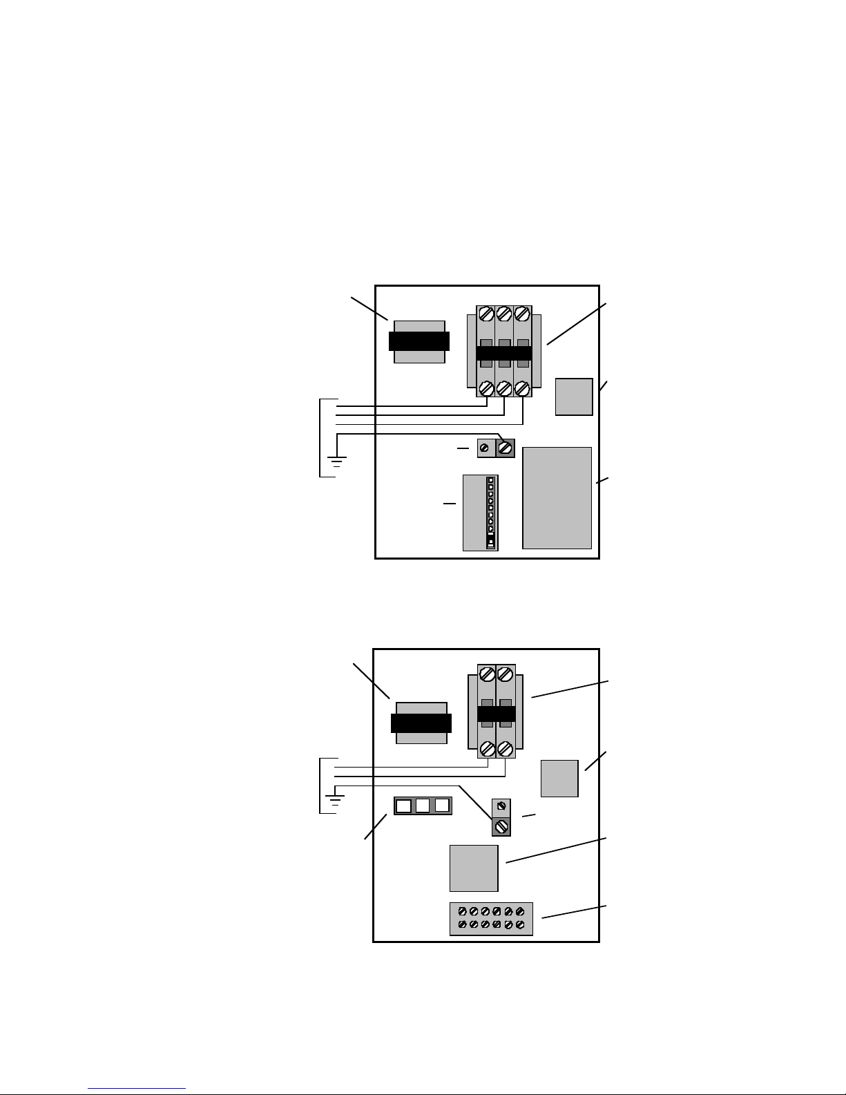
Unit Power Connection
Line voltage connection is made by connecting the incoming line voltage wires to the “L”
side of the contactor as shown in Figure 12 on page 12. Consult the UNIT ELECTRICAL
DATA on page 13 for correct fuse size.
Initial
Desuperheater
Start Up
Electrical
Connections
12
SPECTRA COMMERCIAL AND RESIDENTIAL INSTALLATION GUIDE
208 Volt Operation
All 208-230 volt units are factory wired for 230 volt operation. For 208 volt operation, the
red and the blue transformer wires must be switched between terminal strip PS and
contactor CC.
Figure 12– Spectra SX Line Voltage
Blower
Relay
Compressor
Control
Module
Transformer Compressor
Contactor
Ground
Lug
Typical Electromechanical Control Box
Configuration
Terminal
Board
Power
Strip
Electrical
Supply
with
Ground A C D
Microprocessor
Transformer Compressor
Contactor
Ground Lug
LED Board
Typical Commercial Microprocessor
Control Box Configuration
Electrical
Supply
with
Ground
Blower
Relay

13
SPECTRA COMMERCIAL AND RESIDENTIAL INSTALLATION GUIDE
Compressor Fan
Model Rated Voltage Motor
Total Unit Min. Circuit Max. Max. HACR Total Unit Min. Circuit Max. Max. HACR
Voltage Min./Max. MCC RLA LRA FLA
FLA Ampacity Fuse* Breaker* FLA Ampacity Fuse Breaker
SX010 208-230/60/1 197/254 6.9 4.4 23.0 0.6 10.8 11.9 15 15 5.0 6.1 10 10
265/60/1 239/292 4.6 2.9 16.0 0.6 - - - - 3.5 4.3 6 6
SX013 208-230/60/1 197/254 7.4 4.7 27.0 0.6 11.1 12.3 15 15 5.3 6.5 10 10
265/60/1 239/292 5.4 3.5 22.0 0.6 - - - - 4.1 4.9 6 6
SX016 208-230/60/1 197/254 9.2 5.9 29.0 1.1 12.8 14.3 20 20 7.0 8.5 10 10
265/60/1 239/292 8.5 5.4 27.0 1.0 - - - - 6.4 7.8 10 10
SX019 208-230/60/1 197/254 11.0 7.1 38.0 1.1 14.0 15.7 20 20 8.2 9.9 15 15
265/60/1 239/292 8.6 5.5 32.0 1.0 - - - - 6.5 7.9 10 10
SX024 208-230/60/1 197/254 14.6 9.4 49.0 1.2 16.4 18.7 25 25 10.6 12.9 20 20
265/60/1 239/292 12.8 8.2 44.0 1.1 - - - - 9.3 11.4 15 15
SX030 208-230/60/1 197/254 15.3 9.8 56.0 1.5 17.1 19.6 25 25 11.3 13.8 20 20
265/60/1 239/292 13.8 8.8 55.0 2.0 - - - - 10.8 13.1 20 20
208-230/60/3 197/254 10.5 6.7 51.0 1.5 - - - - 8.2 9.9 15 15
460/60/3 414/506 5.4 3.5 25.0 1.1 - - - - 4.6 5.4 6 6
SX036 208-230/60/1 197/254 21.4 13.7 75.0 2.2 21.7 25.1 35 35 15.9 19.3 30 30
265/60/1 239/292 19.4 12.4 73.0 2.0 - - - - 14.4 17.5 25 25
208-230/60/3 197/254 14.0 9.0 68.0 2.2 - - - - 11.2 13.4 20 20
460/60/3 414/506 6.7 4.3 34.0 1.1 - - - - 5.4 6.5 10 10
SX042 208-230/60/1 197/254 22.5 14.4 82.0 2.8 23.0 26.6 40 40 17.2 20.8 35 35
208-230/60/3 197/254 14.0 9.0 70.0 2.8 - - - - 11.8 14.0 20 20
460/60/3 414/506 7.1 4.6 33.0 1.4 - - - - 6.0 7.1 10 10
575/60/3 518/633 5.3 3.4 27.0 1.4 - - - - 4.8 5.6 6 6
SX048 208-230/60/1 197/254 26.6 17.1 105.0 3.5 26.4 30.6 45 45 20.6 24.8 40 40
208-230/60/3 197/254 16.7 10.7 85.0 3.5 - - - - 14.2 16.9 30 30
460/60/3 414/506 8.2 5.3 42.0 1.8 - - - - 7.1 8.4 10 10
575/60/3 518/633 6.7 4.3 34.0 1.8 - - - - 6.1 7.2 10 10
SX058 208-230/60/1 197/254 37.0 23.7 129.0 4.6 34.1 40.0 60 60 28.3 34.2 50 50
208-230/60/3 197/254 21.0 13.5 99.0 4.6 - - - - 18.1 21.4 30 30
460/60/3 414/506 11.5 7.4 49.0 2.3 - - - - 9.7 11.5 15 15
575/60/3 518/633 9.0 5.8 40.0 2.3 - - - - 8.1 9.5 15 15
SX068 208-230/60/1 197/254 45.0 28.8 169.0 5.9 40.5 47.8 70 70 34.7 42.0 70 70
208-230/60/3 197/254 27.0 17.3 123.0 5.9 - - - - 23.2 27.5 40 40
460/60/3 414/506 14.0 9.0 62.0 3.0 - - - - 12.0 14.2 20 20
575/60/3 518/633 11.0 7.1 50.0 3.0 - - - - 10.1 11.8 15 15
*Includes 5.4 amperage allowance for source side loop pump (up to 1/2 H.P.)
and 0.4 amperage allowance for desuperheater circulating pump operation.
Always refer to unit nameplate data prior to installation.
HACR circuit breaker in United States only. All fuses are class RK-5.
CommercialResidential
Unit Electrical
Data
Unit Operating Pressures*
Cooling** Heating - No Desuperheater
Entering Water Suction Discharge Water Air Suction Discharge Water Air
Water Flow Pressure Pressure Super- Sub- Temp Temp Pressure Pressure Super- Sub- Temp Temp
Temp °F GPM PSIG PSIG heat cooling Rise °F Drop °F DB PSIG PSIG heat cooling Drop °F DB Rise °F
1.5 61-70 100-117 25-35 15-25 21-24 21-26 34-39 163-183 8-12 5-9 7.6-8.4 14-20
30 2.3 62-71 92-109 25-35 15-25 13-16 21-26 37-42 165-185 8-12 5-9 4.8-5.6 16-22
3.0 62-71 88-104 25-35 15-25 6-11 21-26 38-44 167-186 8-12 5-9 3.4-4.2 16-22
1.5 79-85 145-170 15-21 12-25 20-23 20-25 51-58 175-202 10-15 5-9 10.8-11.9 23-29
50 2.3 75-83 130-155 15-21 12-25 12-15 20-25 53-62 178-206 10-15 5-9 6.7-8.1 24-30
3.0 72-82 125-150 15-21 12-25 8-12 20-25 55-65 180-208 10-15 5-9 5.1-5.9 25-31
1.5 78-88 180-200 12-18 13-18 19-22 19-24 71-82 215-250 15-24 3-7 14.0-15.2 28-34
70 2.3 78-90 169-187 12-18 13-18 11-14 19-24 77-89 203-235 15-24 3-7 9.0-10.2 30-37
3.0 78-91 160-180 12-18 13-18 7-12 19-24 81-92 200-235 15-24 3-7 6.7-7.9 31-38
1.5 79-92 230-272 12-18 13-18 18-21 17-23 - - - - - -
90 2.3 80-93 215-248 12-18 13-18 10-14 17-23 - - - - - -
3.0 80-93 208-240 12-18 13-18 6-11 17-23 - - - - - -
*Based on Nominal 400 cfm per ton airflow and 70°F EAT htg. and 80/67°F EAT cooling.
**Cooling air and water numbers can vary greatly with changes in humidity.

14
SPECTRA COMMERCIAL AND RESIDENTIAL INSTALLATION GUIDE
C ommon
E Heat
A uxiliary Heat
F an
2 4VA C
R eversingVa lve
R unSignal
C ompressor
F aultSignal
C C
B lue
2 30V
T ransformer
2 4V
O
L
Y 1
B rown
R V
G
T B
N OTE1
R ed
2 08V
R
P S
Y 2
W 2
W 1
R B
Yellow
B lack
C om
G rey/White
R ed
R BI
5
3
1
2
4
C
B lack
B lack/White
Ta n
R ed
W hite
W hite
O PTIONAL
E MSERIES
A UXILIARY HEAT
X 2
X 1
Ta n
1
3
2
1
3
2
S
L P
H P
B lack
B lack
B lue
L P
H P
C CG
C C
L O
Y
R
C
G reen
11
44
2
2
5
5
3
3
6
6
B lue
Yellow
O range
O range
V iolet
B lue/
W hite
P ink
B lack
O range
B lk/Wht
O range
C CM
B lack/
W hite
B lack
B lack
B lue
B lue
CD
A
C ompressor
U nit
P owerSupply
2 08-230/60/1
C ap
C C
T 1
L 1
T 2
Ta n
R B
B lack
W hite
B rown
C ap
B rown
W hite
P SC
F anMotor
G reen
MHL
L oop
P ump
W hite
B lack
O rangeOrange
G
C
R
S
B lackRed
B lue
F 1 F 1
3
1
C ap
B rn
W h
W hBlk
R ed
G rn
321 C
Yel 4 AirFlow
S ettings
B lu
P SC
F anMotor
N OTE4
N OTE3
D HW
P ump
P inkBlue
O rangeOrange
O range
N OTE2
F 1 F 1
O rangeOrange
H WL
B lack Black
O range
D esuperHeaterOption
3 Airflow
S ettings
4
L 2
O range
F actory lowvoltagewiring
L egend
S witch-Highpressure
S witch-Lowpressure
R elaycoil
Te mperatureLimitSwitch
F ieldwirelug
G round
R elayContacts-
N .O.,N.C.
P olarizedconnector
N otes:
1 -Switchblueandredwiresfor208Voperation.Factory linevoltagewiring
F ieldlowvoltagewiring
F ieldlinevoltagewiring
O ptionalblock
Q uickconnectterminal
W irenut
S crewterminal-
f ieldconnection
2 -BlackandOrangeDSHpumpwireissuppliedwith
d esuperheateroptionbutnotconnectedatfactory.
To enableDSHpumpforoperation,Blackand
C C-
H P-
L P-
R B-
R V-
T B-
R BI-
H WL-
C ompressorcontactor
H ighpressureswitch
L owpressureswitch
B lowerrelay
R eversingvalvecoil
Te rminalboard
B lowerinterlockrelay
H otwatertemperaturelimit
C CM-CompressorControlModule
F 1-Fuse
3 -Orangelooppumpwiresaresuppliedwith
residentialapplicationsbutarenotconnected
O rangewiresmustbeconnectedasshown.
4 -FourspeedblowermotorisusedonSpectra
SX010throughSX012units.Refertoinstructions
C apacitor onblowermotorforchangingspeedsofoperation.
atfactory.
L 1
1
3
2
P
Typical Electromechanical Wiring Schematic
208-230/60/1
97P585A01 1/25/99

15
SPECTRA COMMERCIAL AND RESIDENTIAL INSTALLATION GUIDE
T r ansformer
2 4V
N OTE3
R ed208V
B lue230V
B lackCom
R
C
C
R
C C
C CG
O nO ff
Te st/Normal
L oop/Well
P 2
P 1
S W1
C ommercial/Normal
I O Display/Normal
1
2
3
4
5
P 3
M otorizedVa lve/Normal
F
A
N
F
A
N
C
O
M
C Pu
F P
L P
H P
R V
C O
R B
C C
L SN SE SL OGOYCR
T hermostat
2
4
V
A
C
C
o
m
m
o
n
C
o
m
p
r
e
s
s
o
r
R
V
F
a
n
L
o
c
k
o
u
t
E mergencyShutdown
N ightSetback
L oadshed
N OTE1
N OTE2
R
R
R
R
R
G
Y
R
S W2
S
t
a
t
u
s
L
E
D
P
C
B
1
7
P
5
0
3
A
0
1
R
e
v
A
N OTE4
M V
G rey/White
V iolet
V iolet
Yellow
B lack/White
T
B lack
B lack
B lue
B lue
B rown
O range
O range
Ye llow
Ye llow
3 -Switchblueandredwiresfor208Voperation.
4 -Whenfieldinstalled24VACmotorized
valve(MV)isused,connecttoCandYof
P1,andsetSW1-5totheoffposition.
R elayContacts-
N .O.,N.C.
T hermistor
R elaycoil
S witch-Highpressure
S witch-Lowpressure
P olarizedconnector
C ondensateOverflow
F actory lowvoltagewiring
F actory linevoltagewiring
F ieldlowvoltagewiring
F ieldlinevoltagewiring
O ptionalblock
I nternaljunction
Q uickconnectterminal
W irenut
F ieldwirelug
G round
L 1
L egend
P
N otes:
1 -Requirescommonconnectionor24VACfor
activation.
2 -NightsetbackusedonlywithWaterFurnace
thermostatTA32U02.
O range
D CvoltagePCBtraces
B lue460V
G reen
1
6
2
7
3
8
4
9
5
1 0
C ompressor
C C
T 1
L 1
T 2T 3
C
R
S
R edB lue B lack
L 3 L 2
C ap
B rn
W h
G rn
R B
B rown
B lack
W hite
G
U nit
P owerSupply
2 08-230/60/3
4 60/60/3
5 -Consultinstallationmanualforblowerspeed
wiringinstructions.
N OTE5
C ap
W h
B rn
P SC
F an
M otor
G rn
P 3 OraYe l
M ILI
MHLLIMIH M L
P SC
F an
M otor
B lack W hite
T
1
3
2
C ompressorcontactor
C ondensateoverflow
F reezeprotectionsensor
C C-
C O-
F P-
H P-
L P-
R B-
R V-
S W1-
H ighpressureswitch
L owpressureswitch
B lowerpowerrelay
R eversingVa lvecoil
D IPswitch#1
S W2-Switch#2usedforinput-
o utputdisplay
Typical Commercial Wiring Schematic
208-230/60/3 and 460/60/3
97P577A03 12/1/98

16
SPECTRA COMMERCIAL AND RESIDENTIAL INSTALLATION GUIDE
Installation
Position the thermostat backplate against the wall so that it is level and the thermostat
wires protrude through the middle of the backplate. Mark the position of the backplate
mounting holes and drill holes with a 3/16" bit. Install supplied anchors and
secure plate to the wall. Thermostat wire must be 18 AWG wire. Shielded wire is recom-
mended when running parallel to line voltage wires or conduit for more than 1 foot. Strip the
wires back 1/4" (longer strip lengths may cause shorts) and insert the thermostat wires into
the connectors as shown in Figure 13. Tighten the screws to insure tight connections. The
thermostat has the same type connectors, requiring the same wiring. See instructions
enclosed in the thermostat for detailed installation and operation information.
Thermostat
Figure 13 - Thermostat Wiring
SX Series Fan Blower Motor Airflow (cfm) at External Static Pressure (in. wg)
Model Spd Size HP 0.05 0.10 0.15 0.20 0.25 0.30 0.35 0.40 0.45 0.50 0.60 0.70 0.80 0.90 1.00
H 450 440 420 410 380 360 340 330 310 300 - - - - -
SX010* MH 6 x 8 1/10 410 400 380 370 350 330 310 300 280 270 - - - - -
ML 370 360 340 330 310 290 280 270 250 240 - - - - -
L 310 300 280 270 250 240 230 220 210 200 - - - - -
H450 440 420 410 390 370 350 340 320 310 - - - - -
SX013* MH 6 x 8 1/10 400 390 380 370 350 340 320 310 290 280 - - - - -
ML 370 360 340 330 310 300 290 280 260 250 - - - - -
L 330 320 310 300 290 280 260 250 230 220 - - - - -
H 790 780 775 770 765 760 740 720 690 670 610 - - - -
SX016 M 9 x 7 1/6 720 690 685 680 670 660 650 640 620 600 - - - - -
L 590 570 560 550 545 540 530 520 510 500 - - - - -
H790 780 775 770 765 760 740 720 690 670 610 - - - -
SX019 M 9 x 7 1/6 720 690 685 680 670 660 650 640 620 600 - - - - -
L 590 570 560 550 545 540 530 520 510 500 - - - - -
H1020 990 960 930 900 870 850 830 800 770 690 - - - -
SX024 M 9 x 7 1/5 860 840 820 800 780 760 740 720 690 670 - - - - -
L 720 700 680 650 640 620 600 580 570 550 - - - - -
H1120 1100 1070 1050 1040 1030 1020 1010 1000 980 830 - - - -
SX030 M 9 x 7 1/3 1020 1000 980 960 920 880 860 840 820 790 - - - - -
L 860 850 840 830 810 800 780 760 740 710 - - - - -
H1360 1340 1300 1270 1230 1200 1170 1150 1120 1090 990 870 - - -
SX036 M 9 x 7 1/2 1190 1170 1140 1120 1090 1060 1030 1010 970 930 - - - - -
L 1010 990 970 950 940 920 900 880 860 840 - - - - -
H- - 1730 1700 1670 1650 1620 1580 1540 1490 1400 1290 - - -
SX042 M 10 x 10 1/2 1510 1500 1490 1480 1450 1430 1400 1380 1350 1320 - - - - -
L 1170 1160 1150 1140 1130 1120 1100 1080 1050 1030 - - - - -
H- - 1870 1820 1780 1750 1720 1680 1630 1580 1450 1330 1190 - -
SX048 M 10 x 10 1/2 1710 1660 1630 1590 1560 1530 1490 1460 1410 1370 - - - - -
L 1280 1250 1230 1220 1200 1180 1150 1120 1090 1050 - - - - -
H----2180 2160 2130 2100 2070 2040 1990 1910 1810 1690 -
SX058 M 11 x 10 3/4 2030 2010 1990 1970 1950 1930 1910 1880 1850 1830 1780 - - - -
L 1790 1770 1760 1750 1730 1720 1700 1690 1670 1640 - - - - -
H----2540 2520 2490 2460 2430 2410 2320 2230 2130 1980 1820
SX068 M 11 x 10 1 2430 2390 2360 2340 2310 2290 2270 2250 2220 2190 2120 2050 - - -
L 2000 1980 1970 1950 1930 1920 1900 1860 1830 1780 - - - - -
Factory settings are all high speed except (SX016- M & SX010 MH).
Includes allowance for wet coil and standard filter.
Blower
Performance
Data
R
Y1
C
W
O
G
L1
24VAC
(Hot)
24VAC
(Common)
Compressor
Aux. Heat
Reversing
Valve
Blower
Relay
System
Monitor

17
SPECTRA COMMERCIAL AND RESIDENTIAL INSTALLATION GUIDE
Before Starting Unit, Check The Following:
❏High voltage is correct and matches nameplate
❏Fuses, breakers and wire size correct
❏Low voltage wiring complete
❏Piping completed and water system cleaned and flushed
❏Air is purged from closed loop system
❏Isolation valves are open, water control valves or loop pumps wired
❏Condensate line open and correctly pitched
❏Transformer switched to lower voltage tap if needed
❏Dip switches set correctly (commercial microprocessor only)
❏DHW pump switch off unless piping is completed and air has been purged
❏Blower rotates freely - foam shipping support has been removed
❏Blower speed correct (taps on correct pins)
❏Air filter is clean and in position
❏Service/access panels are in place
❏Return air temperature is between 60-80°F in heating and 70-95°F in cooling
❏Air coil cleaned
Start Up Steps:
1) Initiate a control signal to energize
the blower motor. Check blower
operation.
2) Initiate a control signal to place the
unit in the cooling mode. Cooling
set point must be set below room
temperature.
3) First stage cooling will energize
after a time delay.
4) Be sure that the compressor and
water control valve or loop pumps
are activated.
5) Verify that the water flow rate is
correct by measuring the water
pressure drop through the heat
exchanger using the P/T ports and
comparing to water pressure drop
found in Table 3.
6) Check the temperature of both the
supply and discharge water. Refer
to Start Up Performance Table 2
7) Check for an air temperature drop
of 15°to 25°F across the air coil,
depending on the fan speed and
entering water temperature. Refer
to unit operating pressures on
page 13.
8) Adjust the cooling set point above
the room temperature and verify
that the compressor and water
valve or loop pumps deactivate.
Unit Start Up
Table 3 - Water Pressure Drop Table
Table 2 - Temperature Change Through Heat Exchanger
Water Flow Rate Water Temperature
(GPM) Change (Deg °F)
Rise (Clg) Drop (Htg)
For Closed Loop: Ground Source or 9 - 12 4 - 8
Cooler/Boiler systems at 3 gpm/ton
For Open Loop: Ground Water systems 20 - 26 10 - 17
at 1.5 gpm/ton
FLOW RATE PRESSURE DROP (PSI)
MODEL GPM 30°F50°F90°F
1.5 2.1 2.0 1.9
SX010 2.0 3.4 3.2 3.0
2.5 5.2 4.9 4.6
1.5 2.0 1.9 1.8
SX013 2.5 4.6 4.4 4.1
3.5 8.1 7.7 7.2
2.0 3.0 2.9 2.7
SX016 3.0 5.9 5.7 5.3
4.0 9.7 9.3 8.7
3.0 1.2 1.2 1.1
SX019 4.0 2.1 2.0 1.9
5.0 3.5 3.3 3.1
3.0 1.5 1.4 1.3
SX024 4.5 3.2 3.1 2.9
6.0 6.0 5.8 5.4
4.0 1.2 1.2 1.1
SX030 5.5 2.1 2.0 1.9
7.0 3.2 3.1 2.9
5.0 2.4 2.2 2.1
SX036 7.0 3.9 3.7 3.5
9.0 6.2 5.9 5.5
5.0 1.7 1.6 1.5
SX042 8.0 3.5 3.3 3.1
11.0 6.2 5.9 5.5
6.0 3.5 3.1 2.3
SX048 9.0 6.7 5.9 4.2
12.0 10.7 9.5 7.0
8.0 4.1 3.7 2.8
SX058 11.0 6.6 6.0 4.7
14.0 10.0 8.9 6.6
10.0 6.1 5.4 3.9
SX068 13.0 9.3 8.2 6.0
16.0 13.0 11.7 9.0
Note: To obtain maximum performance the air coil should be cleaned
before start up. A 10% percent solution of dishwasher detergent and water
is recommended for both sides of coil. A thorough water rinse should follow.

18
SPECTRA COMMERCIAL AND RESIDENTIAL INSTALLATION GUIDE
9) Initiate a control signal to place the unit in the heating mode. Heating set point must
be set above room temperature.
10) First stage heating will energize after a time delay.
11) Check the temperature of both the supply and discharge water. Refer to Table 2 on
page 17.
12) Check for an air temperature rise of 20°to 35°F across the air coil, depending on the
fan speed and entering water temperature. Refer to Unit Operating Pressure on
page 13.
13) If auxiliary electric heaters are installed, adjust the heating set point until the electric
heat banks are sequenced on. All stages of the auxiliary heater should be sequenced
on when the thermostat is in the "Emergency" Heat mode. Check amperage of
each element.
14) Adjust the heating set point below room temperature and verify that the compressor
and water valve or loop pumps deactivate.
15) During all testing, check for excessive vibration, noise or water leaks. Correct or repair
as required.
16) Set system to desired normal operating mode and set temperature to maintain desired
comfort level.
17) Instruct the owner/operator of the proper operation of the thermostat and system
maintenance.
18) During all testing, check for excessive vibration, noise or water leaks. Correct or repair
as required.
19) Set system to desired normal operating mode and set temperature to maintain desired
comfort level.
20) Instruct the owner/operator of the proper operation of the thermostat and system
maintenance.
NOTE: If performance during any mode appears abnormal, refer to the troubleshooting
section on page 19.
Water Coil Maintenance
1) Keep all air out of the water. An open loop system should be checked to insure that the
well head is not allowing air to infiltrate the water line. Lines should always be airtight.
2) Keep the system under pressure at all times. It is necessary in open loop systems that
the water control valve be placed in the discharge line to prevent loss of pressure
during off cycles. Closed loop systems must have positive static pressure or air vents
may draw air into the system.
NOTE:
If the installation is performed in an area with a known high mineral content (125
P.P.M.or greater) in the water, it is best to establish with the owner a periodic maintenance
schedule so the coil can be checked regularly. Should periodic coil cleaning be necessary,
use standard coil cleaning procedures which are compatible with either the cupronickel or
copper water lines. Generally, the more water flowing through the unit the less chance
for scaling.
Other Maintenance
Filters - Filters must be clean to obtain maximum performance. They should be in-
spected every two to three months under normal operating conditions and be replaced
when necessary. Units should never be operated without a filter.
Preventive
Maintenance

19
SPECTRA COMMERCIAL AND RESIDENTIAL INSTALLATION GUIDE
Condensate Drain - In areas where airborn bacteria produce a slime in the drain pan, it
may be necessary to treat chemically to minimize the problem. The condensate drain can
pick up lint and dirt, especially with dirty filters. Inspect twice a year to avoid the possibility of
overflow.
Air Coil - The air coil must be cleaned to obtain maximum performance. Check once a
year under normal operating conditions and, if dirty, brush or vacuum clean. Care must be
taken not to damage the aluminum fins while cleaning.
CAUTION: Fin edges are sharp.
Desuperheater Coils - See Water Coil Maintenanc, page 18.
CONTROLS
Commercial Microprocessor
To check the unit control board for proper operation:
1) Place control board into “Diagnostics-inputs” mode (see Schematic page 14 and 15).
Place Switch #1 in “Test” mode. Remember to place Switch #1 back to “Normal” mode
before leaving.
2) Adjust thermostat to “Call” for heating or cooling.
3) Check LEDs for proper operation.
4) If LEDs indicate proper operation of thermostat, check “Diagnostics-Outputs”.
5) If LEDs are not indicating proper operation, remove thermostat connections.
• Jumper desired test input (Y, O, G) to “R” to simulate a thermostat signal.
• Check operation with “Diagnostics-input” mode.
• Check thermostat and field control wiring.
• If steps above show that the unit control board is not indicating proper results
(i.e. LED indication), replace board.
• If LEDs are indicating properly, replace thermostat.
6) Do not replace unit control board or thermostat until all diagnostic checks
have been made.
Residential Electromechanical
The compressor control module has a test mode that resets all timed delays to seconds
in duration. Simply ground the 1/4" spade connector labeled "test" to initiate test mode.
REFRIGERANT SYSTEM
To maintain sealed circuit integrity do not install service gauges unless unit operation
appears abnormal. Reference the operating chart on the page 13.
Verify that air and water flow rates are at proper levels before servicing the refriger
ant circuit.
Obtaining Parts
When contacting WaterFurance International for service or replacement parts, refer to
the model number and serial number of the unit as stamped on the serial plate attached to
the unit. If replacement parts are required, mention the date of installation of the unit and the
date of failure, along with an explanation of the malfunctions and a description of the
replacement parts required.
In-Warranty Material Return
Material may not be returned except by permission of authorized WFI service personnel.
Contact your local distributor or the WFI service department for warranty return authorization
and assistance.
Troubleshooting
Replacement
Procedures

WaterFurnace has a policy of continuous product research and
development and reserves the right to change design and speci-
fications without notice. WaterFurnace is a registered trademark
and Spectra is a trademark of WaterFurnace International, Inc.
©1999 WaterFurnace International, Inc.
9000 Conservation Way
Fort Wayne, IN 46809-9794
Phone: 1-219-478-5667 or
1-800-934-5667
FAX: 1-800-783-5667
http://www.waterfurnace.com
In Canada Call: 1-800-463-8108
P/N 96P537A01 4/99
This manual suits for next models
17
Table of contents
Other Water Furnace Temperature Controllers manuals


Popular Temperature Controllers manuals by other brands


dixell
dixell XH460L operating instructions

Daikin
Daikin OM-SLM-0501 Operation manual

AMX
AMX AXC-TEMP AND RTS-1 TEMPERATURE CONTROL CARD AND ROOM TEMPERATURE... instruction manual

Liebert
Liebert Liebert iCOM user manual

Powtier Controls
Powtier Controls TC308 instruction manual

Danfoss
Danfoss EKC 366 manual


