Water Furnace IntelliZone2 BACnet User manual

Installation Information
Damper Installation
Thermostat Installation
Electrical
Startup Procedures
Wiring Schematic
IM1588EW 11/20
IntelliZone2 BACnet Installation Manual
Six Zone Capability
Comfort Zoning System
a
ti
on
n
a
ti
o
n
s
Int
e
lliZ
o
n
e
2
B
Comfort Zoning Syste
m


INTELLIZONE2 BACNET INSTALLATION MANUAL
Table of Contents
IntelliZone2 BACnet Components . . . . . . . . . . . . . . . . . . . . . . . . . . . . . . . . . . . . . . . . . . . . . . . . . . . 4
General Installation Information . . . . . . . . . . . . . . . . . . . . . . . . . . . . . . . . . . . . . . . . . . . . . . . . . . . . . 5
Damper Installation . . . . . . . . . . . . . . . . . . . . . . . . . . . . . . . . . . . . . . . . . . . . . . . . . . . . . . . . . . . . . . . . 6
Electrical Wiring. . . . . . . . . . . . . . . . . . . . . . . . . . . . . . . . . . . . . . . . . . . . . . . . . . . . . . . . . . . . . . . . . . . 9
Zone Selection . . . . . . . . . . . . . . . . . . . . . . . . . . . . . . . . . . . . . . . . . . . . . . . . . . . . . . . . . . . . . . . . . . . .12
IntelliZone2 BACnet Configuration/Diagnostics . . . . . . . . . . . . . . . . . . . . . . . . . . . . . . . . . . . . . . .13
IntelliZone2 BACnet Configuration/Wiring . . . . . . . . . . . . . . . . . . . . . . . . . . . . . . . . . . . . . . . . . . 20
Description of Operation - Package Unit . . . . . . . . . . . . . . . . . . . . . . . . . . . . . . . . . . . . . . . . . . . . .21
Blower Data - Package Unit. . . . . . . . . . . . . . . . . . . . . . . . . . . . . . . . . . . . . . . . . . . . . . . . . . . . . . . . 23
IntelliZone2 BACnet CFM Design . . . . . . . . . . . . . . . . . . . . . . . . . . . . . . . . . . . . . . . . . . . . . . . . . . . 27
System Startup and Checkout. . . . . . . . . . . . . . . . . . . . . . . . . . . . . . . . . . . . . . . . . . . . . . . . . . . . . . 27
Wiring Schematic. . . . . . . . . . . . . . . . . . . . . . . . . . . . . . . . . . . . . . . . . . . . . . . . . . . . . . . . . . . . . . . . . 29
IntelliZone2 BACnet Fault Codes . . . . . . . . . . . . . . . . . . . . . . . . . . . . . . . . . . . . . . . . . . . . . . . . . . . 30
Revision Guide . . . . . . . . . . . . . . . . . . . . . . . . . . . . . . . . . . . . . . . . . . . . . . . . . . . . . . . . . . . . . . . . . . . 32

4
INTELLIZONE2 BACNET INSTALLATION MANUAL
IntelliZone2 BACnet Components
IntelliZone2 BACnet Zoning Board
The IntelliZone2 BACnet zoning board is the master control for the system,
has much of the programming for operation, provides basic relay logic for
the damper operation and serves as a common connection point for the
IntelliZone2 XPC Control and the heat pump.
IntelliZone2 BACnet XPC Control
The IntelliZone2 BACnet XPC Control provides the BACnet interface for the
system to the BAS. It is a communicating device that connects to all zone
sensors.
IntelliZone2 BACnet Zone Sensors
The IntelliZone2 BACnet Zone Sensors are used for all zones. Sensors are
available with humidity, CO2 and VOC options as well as with and without
temperature display and setpoint adjustment controls.
Note: Only one zone sensor with a CO2 or VOC option may be used per system.
IntelliZone2 Damper System
The IntelliZone2 BACnet Damper Systems come in round or rectangular
construction with 2 or 3-wire accuators.
5
INTELLIZONE2 BACNET INSTALLATION MANUAL
Safety Considerations
Installing and servicing heating and air conditioning
equipment can be hazardous due to system electrical
components. Only trained and qualified service personnel
should install, repair or service heating and air conditioning
equipment. When working on equipment, observe
precautions in the literature, tags and labels attached to the
unit, and other safety precautions that may apply. Follow all
safety codes. Wear safety glasses and work gloves.
WARNING: Before performing service or
maintenance operations on the system, turn
off main power switches to the indoor unit.
Turn off accessory heater power switch if
applicable. Electrical shock could cause
serious personal injury.
Delivery Information
When the equipment is received, all items should be
carefully checked against the bill of lading to be sure
all crates and cartons have been received. Examine the
contents for shipping damage, removing them from the
cartons if necessary. If any damage is noted, the carrier
should make the proper notation on the delivery receipt,
acknowledging the damage.
General rules to follow when installing a zone
system:
CAUTION: When installing the IntelliZone2
BACnet in a structure with fossil fuel (oil, gas,
propane) appliances, it is important that both
supply and return dampers are used in each zone
to avoid potential back-drafting of fossil-fueled
appliances.
• Up to six zones on variable speed, up to 4 zones with
dual capacity units (two with single speed units).
• All dampers should be located as close to the main
trunk as possible to limit the amount of pressurized
trunk line and thus limit air leakage.
• No less than three branch runs in a zone to prevent
a single branch obstruction (curtains or clothes etc.)
from affecting unit airflow.
• Insulate and seal around rectangular dampers to
prevent leakage.
• All dampers must be wired with 18-gauge wire.
NOTE: Crimp connections should never be used on
solid conductor wire.
• Ensure that the transformer can handle the power
requirements of the system.
• No more than three dampers per zone.
General Installation Information
Installation and Design Steps
1. Decide which areas of a building or office will comprise
each of the individual zones. A maximum of six
individual zones (four with dual capacity and two with
single speed equipment) can be chosen.
2. Calculate loads using software or other
recognized methodology.
3. Use software to determine the equipment size and
performance based on the total heating and cooling
demands of the building, not the sum of the individual
zone demands.
4. Find the peak heating and cooling demands and the
peak cfm required for each of the zones.
5. Determine zone design air flow and zone size settings
using IntelliZone2 BACnet Design software.
6. Lay out and size the supply air ductwork and dampers.
Care should be taken to avoid under sizing either the
supply air systems, return air systems, or diffusers.
7. Decide where to locate the zone sensors.
8. Install the unit and the IntelliZone2 BACnet Comfort
Zoning system.
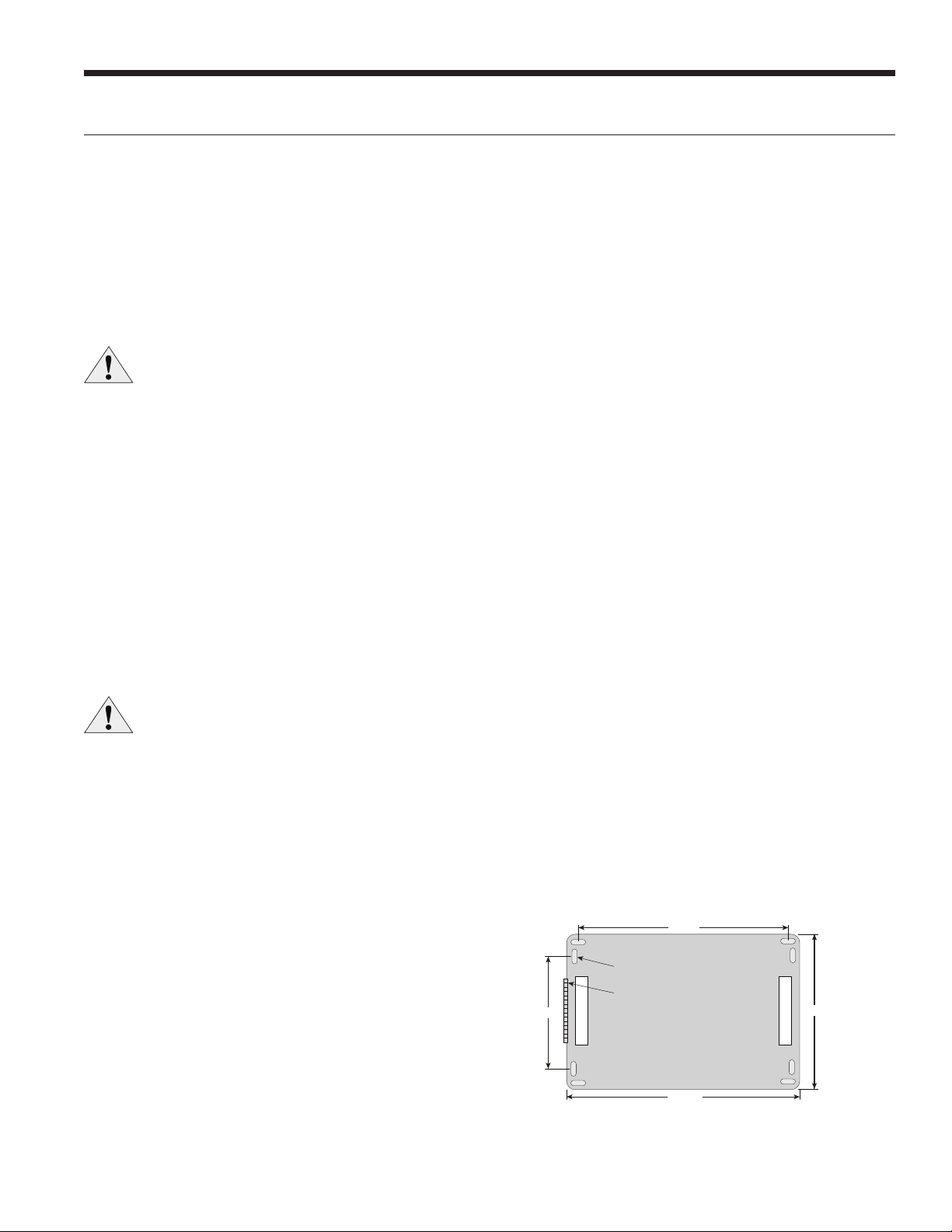
IntelliZone2 BACnet Control Panel
Locate the IntelliZone2 BACnet panel in an indoor area
that has enough space for service personnel to perform
maintenance or repair. Provide sufficient room to make
electrical connection(s). The IntelliZone2 BACnet is not
approved for outdoor installation and, therefore, must be
installed inside the structure being conditioned. Do not
locate the control panel in areas where ambient conditions
are not maintained within 45°F to 95°F and are greater
than 75% relative humidity. The IntelliZone2 BACnet control
panel should be mounted on or as close to the unit as
possible by using the sheet metal screws provided. See
Figure 1 for mounting hole locations.
NOTE: IntelliZone2 BACnet Relay Panel to be mounted
indoors.
Figure 1: IntelliZone2 BACnet Relay Panel Mounting
NOTE: Use longer screws (not provided) to penetrate
through drywall into stud.
9.25 in.
6.00 in. 7.75 in.
10.35 in.
Hinge Side
D
epth = 2.00 in. Deep with cover
Wire Access
Wire Access
Mounting Slots

6
INTELLIZONE2 BACNET INSTALLATION MANUAL
Six Zone System Representational Layout
Installing Rectangular Dampers in
Metal Ductwork
1. Cut out dimensions A and B as shown in Figure 2 by
using sheet metal snips. NOTE: Dimensions A and B are
listed in the Dimensional Examples table.
2. Use foam insulation tape on the top and bottom of
the zone damper to prevent excessive air bypass. Also
check the cross emboss for excessive air bypass (see
Figure 2).
3. Slide the zone damper into the ductwork making
sure no obstructions will interfere with damper blade
operation.
4. Use the screws provided to mount the damper flange
to the ductwork. Four to six mounting holes are
provided as shown in Figure 3.
5. Use drive cleats or regular duct mounting brackets to
attach ductwork to joist within six inches on both sides
of the damper (see Figure 3).
6. Check damper blade operation for obstructions by
holding the manual release button and rotating the
damper shaft CCW (Open) and CW (Closed) 3 Wire
only as shown in Figure 4.
Damper Installation
Manual release
CW
Closed
CCW
Open
Rotate by hand
Figure 4: Checking Damper Blade for Obstructions
Cross emboss for
duct stiffness may
cause excessive
air bypass
Foam Seal
Foam Tape
(top and bottom)
A
B
3.75”
Figure 2: Foam Taping Zone Damper
Figure 3: Mounting Damper
Mounting Screws
(4 places)
Attach duct/damper
to joist within 6" on
both sides
Dimensional Examples
Damper
Model HWA B
ZDR1024 10 in. 24 in. 10 in. 3.75 in.
ZDR0812 8 in. 12 in. 8 in. 3.75 in.
Premier2
72
72
72
72
72
72
C
e
Cl

7
INTELLIZONE2 BACNET INSTALLATION MANUAL
Insulating Rectangular Dampers in
Metal Ductwork
Insulate ductwork as shown in Figure 5. All metal must
be covered. Care must be taken not to obstruct the shaft
from rotating when insulating. Do not insulate the zone
damper actuator.
Installing Rectangular Dampers
in Duct
1. Cut out dimensions A and B by using a duct
knife. NOTE: Dimensions A and B are listed in the
Dimensional Examples table.
2. A duct spacer should be installed on the end of
the damper frame as shown in Figure 7 to prevent
excessive air bypass. For example: A one-inch-thick,
8 in. x 20 in. duct and a 8 in. x 20 in. zone damper
would have a one-inch gap at the end of the frame
once it is installed without a duct spacer. Use the piece
cut out for installation.
3. Foam insulation tape should be used on the top and
bottom of the zone damper to prevent excessive air
bypass as shown in Figure 7.
4. Slide the zone damper into the duct making
sure no obstructions will interfere with damper
blade operation.
5. Tape the damper face flange to the duct using foil
tape making sure the damper is secure and air tight as
shown in Figure 8.
6. Support the full length of the duct underside within six
inches and on both sides of the damper as shown in
Figure 8.
7. Check the damper blade operation for obstructions
by holding the manual release button and rotating the
damper shaft CCW and CW (see Figure 4).
Damper Installation cont.
Do not insulate zone
damper actuator
Duct wrap insulation
Figure 5: Insulating Rectangular Metal Ductwork
A
B
Duct board
Keep spacer clear
of end bushing
Foam tape
(top and bottom)
Insulate between
actuator and damper
spacer
Figure 7: Taping Zone Damper with Foam Tape
Foil tape damper face
to ductboard
Support the full length of ductboard
underside within 6” of damper
Figure 8: Taping Damper Flange to Duct
8
INTELLIZONE2 BACNET INSTALLATION MANUAL
Insulating Rectangular Duct/
Metal Sleeve
Care must be taken not to obstruct the shaft from rotating
when insulating. Do not insulate the zone damper actuator.
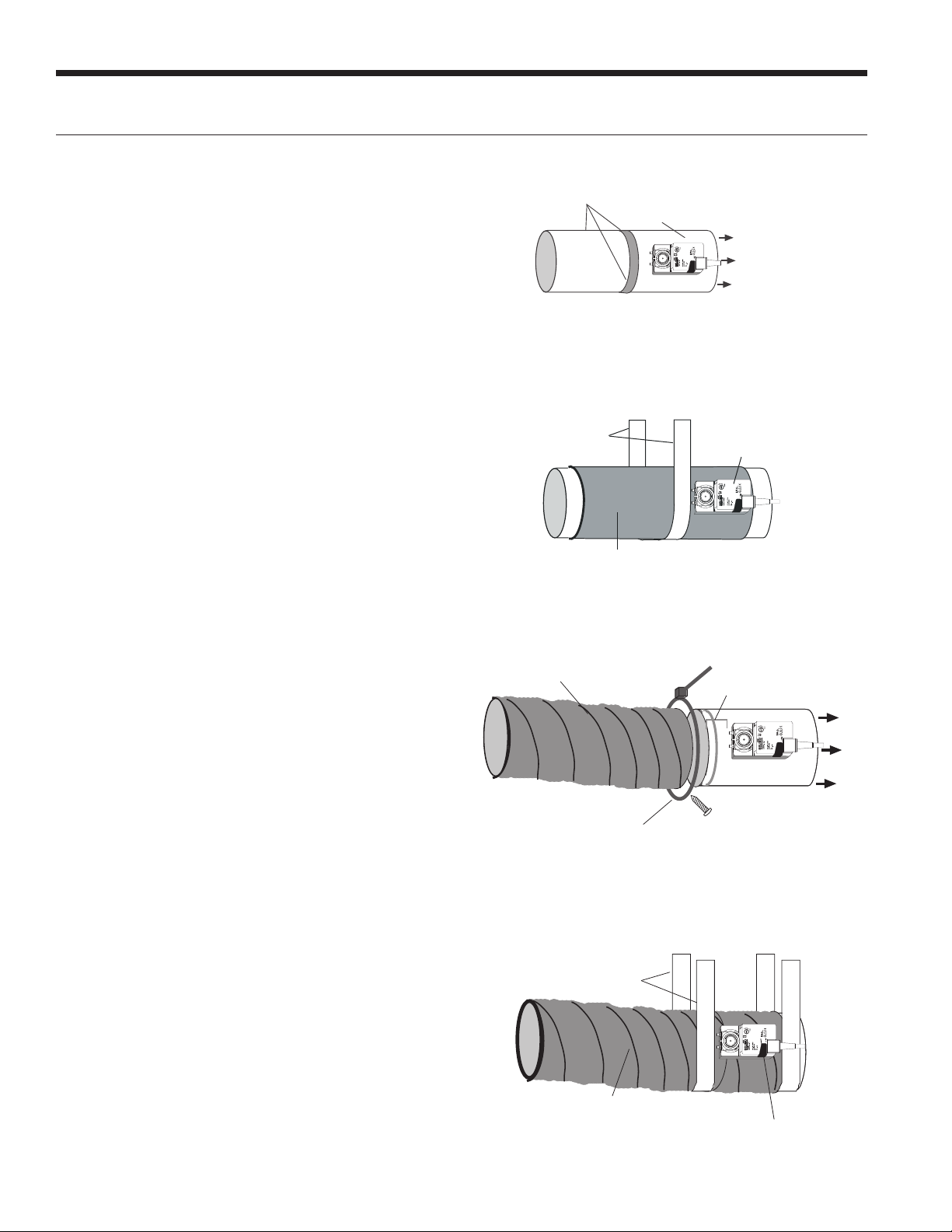
Installing Circular Dampers in Round
Metal Duct
1. Crimp the end of the duct that is the supply air to
damper. Insert into circular damper no more than
1.5 inches.
2. Fasten the duct to the damper with three screws.
Screws installed more than one inch from either end
may obstruct damper blade rotation.
3. Seal completely around the duct with metal duct tape
or mastic to prevent air leakage as shown in Figure 10.
4. Check the damper blade operation for obstructions by
holding the manual release button and rotating damper
shaft CCW and CW (3 wire only). See Figure 4.
5. Support the duct to joist within six inches of the
damper as shown in Figure 9.
Insulating Circular Dampers in Round
Metal Duct
Insulate ductwork as shown in Figure 10. All metal must be
covered to prevent condensation. Care must be taken not
to obstruct the shaft from rotating when insulating. Do not
insulate the zone damper actuator.
Installing Circular Dampers in
Flexible Duct
1. Slide flexible duct two to three inches over the damper
pipe past the damper rib as shown in Figure 11.
2. Fasten duct to damper with a nylon duct strap,
screwing the strap to the pipe to prevent the duct from
slipping off. Screws installed more than one inch from
either end may obstruct damper rotation.
3. Seal completely around the duct with metal duct tape
or mastic to prevent any air leakage.
4. Check the damper blade operation for obstructions by
holding the manual release button and rotating damper
shaft CCW (Open) and CW (Closed) - 3 wire only. See
Figure 4.
5. Support the damper to joist within six inches on both
sides of the damper as shown in Figure 12.
Insulating Damper Actuators
Insulate the damper as shown in Figure 12. All metal must
be covered to prevent condensation. When insulating, care
must be taken not to obstruct the shaft from rotating. Do
not insulate the zone damper actuator.
Damper Installation cont.
Support with wide
steel strap
1-1/2’’or 2’’ if in unconditioned space
Do not insulate
damper actuator
Figure 12: Supporting and Insulating Circular Damper
Flexible duct
Clamp with duct strap. Install screw no farther
than 1” from either end of damper
Slide duct 2-3’’ past
damper end rib
Air Flow
Figure 11: Attaching Flexible Duct to Damper
Three screws sealed
with duct tape or mastic
Manual release button
Air Flow
Figure 9: Taping Round Duct to Circular Damper
Do not insulate
damper actuator
1-1/2" or 2" if in unconditioned space
Support with
wide steel strap
Figure 10: Supporting and Insulating Circular Damper

9
INTELLIZONE2 BACNET INSTALLATION MANUAL
Wiring Damper Actuators
All wiring must comply with local and state codes.
Disconnect the power supply before beginning to wire to
prevent electrical shock or equipment damage. All wiring
should be run back to the control panel. Keep wires a
minimum of 12 inches from any high voltage lines. Follow
the damper wiring schematic as shown in Figure 13. Verify
that damper rotation direction is correct. The 3-wire
damper rotation direction is reversible with switch on front
cover.
Figure 13: Damper Actuator Wiring
Electrical Wiring
Wire Nuts Strain Relief
Figure 14: Actuator Wiring
Damper Actuator Wiring Notes
1. Minimum of 18-gauge thermostat wire is recommended.
2. Use wire nuts to connect the thermostat wire to the
actuator wire (solid wire to stranded wire) as shown in
Figure 14.
3. The actuator wiring should be secured using a wire tie to
prevent the wires from being separated (see Figure 14).
3-Wire Damper
Zone 4
Com
Open
Close
G
Minimum
18-gauge wire
(Indicated rotation direction
is valid for switch position ‘0’ )
BlkCOM
Grn
CCW
Red
CW
IntelliZone/IntelliZone2 PCB
2-Wire Damper
Minimum
18-gauge wire
Zone 4
IntelliZone/IntelliZone2 PCB
Com
Open
Close
G
COM Gray
CCW Yellow
Damper Switch
Reverse Rotation
Note:
1. Each zone must have
dampers that match by
manufacturer and type.
2. Each IntelliZone
System must have
dampers that match,
either 2-wire or 3-wire.
IntelliZone2 BACnet
IntelliZone2 BACnet
10
INTELLIZONE2 BACNET INSTALLATION MANUAL
WARNING: All wiring must comply with local
and state codes. Disconnect the power supply
before beginning to wire to prevent electrical
shock or equipment damage.
Mount the transformer onto the side of the unit’s control
box by inserting and tightening screws (provided) into the
pre-punched holes. Thread all transformer wires through
the hole with bushing and follow the wiring schematic for
connecting the transformer primary and secondary leads
as shown in Figure 15 and Figure 16 examples. NOTE: Actual
control box layout may vary depending on the product
configuration.
For 208 volt operation, the red and blue transformer wires
must be switched. Use wire nuts only for connections to
thermostat wire.
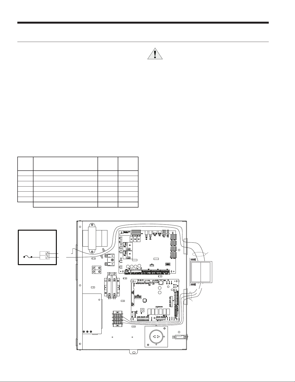
Transformer Sizing
The heat pump transformer should never be used to power
the zone dampers. Damage to the heat pump or dampers
may occur. Providing adequate transformer power (VA)
to supply the system is an important requirement. Each
IntelliZone2 BACnet 3-wire damper requires 3.0VA at
nominal voltage and each 2-wire damper requires 7.0VA
at nominal voltage. The standard available transformer is
a 75VA with an integrated circuit breaker (Part # ZTK240
or ZTK460). The Transformer ‘VA’ Calculation table shows
a sample sizing procedure for both the 3-wire and 2-wire
dampers that should be carried out for each installation.
If the total VA is greater than 70VA, then a second 75VA
transformer should be wired in parallel to provide a total
power capability of 150VA. As the ‘VA’ Calculation table
shows the 2-wire damper requires much more VA than the
3-wire damper.
Transformer ‘VA’ Calculation
Zone Number of Dampers
Powered in Zone
3-Wire
Actuator
2-Wire
Actuator
113.07.0
213.07.0
3 2 6.0 14.0
4 3 9.0 21.0
5 2 6.0 14.0
613.07.0
Total VA Draw (10 Dampers) 30.0 70.0
Electrical Wiring cont.
Figure 15: Mounting and Wiring Transformer to Control Box (Versatec VS shown)
R
C
P18
Damper Power
F1 Damper
Fuse Black/White
5A Fuse
IntelliZone2
Relay Board
Primary Leads
Secondary
Leads
Zone
Transformer
75 VA
(PN) ZTK240
Black
Blue
Red
Yellow
AXB
ABC
PB2
11
INTELLIZONE2 BACNET INSTALLATION MANUAL
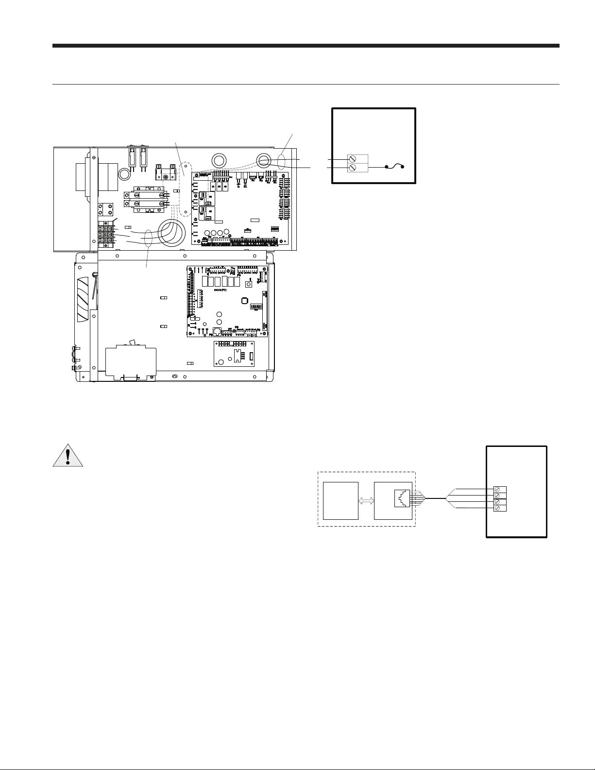
Wiring IntelliZone2 BACnet to the Unit
WARNING: All wiring must comply with local
and state codes. Disconnect the power supply
before beginning to wire to prevent electrical
shock or equipment damage.
Follow the wiring schematic in Figure 17 for unit control
connections. Insert the wires from the supplied harness into
the zoning board connector as shown in Figure 17. Tighten
the screws to ensure tight connections.
Figure 16: Mounting and Wiring Transformer to Control
Box
Figure 17: IntelliZone2 BACnet to Heat Pump Control
Electrical Wiring cont.
A+
R
C
B-
P17 – Heat Pump
IZ2 BACnet
Control Board
P8
Aurora ABC
Aurora AXB
Heat Pump Controls
12345678
Red & Orange
Black & White
Blue & Green
Brown & Yellow
Zone Transformer
(mounted on backside
of control box)
R
C
P18
Damper Power
F
1 Damper
Fuse
5A Fuse
IntelliZone2
Relay Board
Black/White
Yellow
Black Blue
Red
Secondary
Leads
Primary
AXB
ABC
PS
Leads
NOTE: The harness supplied with the IntelliZone2 BACnet
is designed to plug into the Aurora ABC P8 connector
only.
12
INTELLIZONE2 BACNET INSTALLATION MANUAL
Zone Selection
General Zone Selection Rules
• Minimum of three branch runs per zone.
• Zone together areas of like uses, but separate areas
based on differing uses
• Avoid grouping rooms of different levels or floors into the
same zone.
• Avoid grouping rooms with opposite sun or weather
exposures in the same zone.
NOTE: Ensure zone duct is designed to handle cfm required
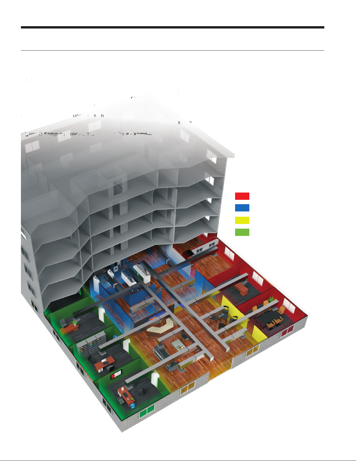
Locating the Zone Sensors
The zone sensors must be located in the room or zone
that each controls. Locate a zone sensor about five feet
above the floor. Do not locate a zone sensor where it may
be exposed to direct sunlight, drafts or direct supply air.
Do not place a zone sensor on an outside wall. Follow the
same guidelines that apply with standard zone sensor
installation. If two or more rooms are on a single zone,
locate the zone sensor in a hallway or area where it can
sense the return air from all rooms.
Figure 1: Sample Floor Plan with Four Zone Example
•
Minimum
of
three
branch
runs
per
zon
e.
•
Zone to
g
ether areas of like uses, but separate areas
based on differin
g
use
s
•
Avoid grouping rooms of different levels or floors into the
sam
e
z
o
n
e.
•Avoi
d
grouping rooms wit
h
opposite s
un
o
o
r
r
w
we
at
h
er
exposures in the same zone
.
NO
TE
:
Ensure zone
d
d
d
d
uc
uc
uc
u
t
t
t
i
is
is
d
d
es
es
ig
ig
ne
ne
d
d
to handle cfm requir
ed
The
zone
sensors
must
be
located
in
the
room
or
zo
ne
that each controls. Locate a zone sensor about five fe
a
bove the floor. Do not locate a zone sensor where it
m
be exposed to direct sunlight, dra
f
ts or direct suppl
y
a
D
o not place a zone sensor on an outside wall. Follow
same guidelines that appl
y
with standard zone sens
or
installation. I
f
two or more rooms are on a single zon
e
lo
lo
ca
c
te the zone sensor in a hallwa
y
or area where it c
a
se
se
ns
s
e
e
e
th
e
r
e
turn air fr
o
m all r
oo
ms
.
Fi
Fi
Fi
Fi
Fi
Fi
Fi
Fi
Fi
Fi
Fi
Fi
Fi
F
Fi
gu
gu
gu
gu
gu
gu
gu
gu
g
g
re
re
re
re
re
re
r
re
e
e
e
e
e
e
e
e
e
e
1
1
1
1
1
1
1
1
1
1
1
1
1
1
1
1
1
1
1
:
:
:
:
:
:
:
:
:
:
:
:
:
:
:
:
:
S
Sa
Sa
Sa
Sa
Sa
a
S
Sa
Sa
Sa
S
S
Sa
Sa
Sa
Sa
Sa
mp
mp
mp
mp
mp
m
mp
p
mp
p
p
p
mp
p
p
p
l
le
le
l
l
le
le
le
le
le
le
e
F
F
F
F
F
F
F
F
lo
lo
o
o
o
o
o
o
o
o
o
o
o
o
o
o
or
or
or
or
or
or
or
P
P
P
P
P
la
la
la
la
la
n
n
n
nn
wi
wi
wi
wi
wi
th
h
th
th
t
F
F
ou
ou
r
r
r
Zo
Zo
Zo
Zo
nene
e
e
ne
E
E
E
E
E
E
E
xa
xa
xa
xa
x
a
mp
mp
mp
mp
mp
m
le
le
le
le
Zone 1 Offices
Zone 2 Utility Space
Zone 3 Lobby
Zone 4 Offices

13
INTELLIZONE2 BACNET INSTALLATION MANUAL
IntelliZone2 BACnet Configuration/Diagnostics
For configuration of the IZ2 BACnet system and viewing di-
agnostic values, the Equipment Touch Application for An-
droid based tablets may be used. This software application
allows you to connect to the unit in real time to configure
and monitor the IZ2 BACnet system. The interface is very
user friendly and easy to follow. The tablet is connected
to the system via a USB-C adaptor and cable that is con-
nected to the XPC or to a Rnet zone sensor
Home Screen
The home screen shows an overview of the current operat-
ing status of the IZ2 BACnet system as well as links to the
configuration and detailed diagnostic screens.
Systems Settings
The System Settings screen is used to set most system
level IZ2 BACnet operating parameters.
Equipment Touch Software Icon
Equipment Type
Selection for the heat pump being controlled by the IZ2
BACnet system. The selection options are Variable Speed,
Dual Capacity, and Single Capacity.
Number of Zones
Selection for the number of zones controlled by the system.
The selection options are from 2 to 6, depending on the
Equipment Type.
Single Capacity – Maximum of 2 zones
Dual Capacity – Maximum of 4 zones
Variable Speed – Maximum of 6 zones
Zoning Operation
This option allows selects the mode of operation for the
Zoning system.
Normal – Normal operation uses the individual
zone conditions to operate the system dampers
and equipment.
Central Zone – In Central Zone mode all dampers
are opened, and zone condition readings are taken
ONLY from Zone 1. This will approximate operation
without a zone system and can be useful during
initial commissioning or during service etc.
Damper Type
Selection of system damper type of either Spring (2 wire
spring closed) or Power (3 wire power open/power closed).
Damper Time
Selection to set the amount of time in seconds that the sys-
tem dampers take to open or close. The damper operation
time can be set from 30 to 120 seconds.
PID Selection
Selection to determine how quickly the system heating and
cooling demands will increase and decrease. When the Ag-
gressive value is selected, all system heating and cooling
demands will ramp up and down more quickly.
Scheduling Option
Selection between using the internal program schedules
and network control where the occupied / unoccupied con-
dition is set by the BAS.
Staging
The staging options allows custom selection of staging for
heating and cooling operation. The IntelliZone2 BACnet
system allows separate staging options for heating and
cooling. There are four distinct options for heating and
cooling modes which are explained below. Once compres-
sor operation has been initiated by a zone demand, the
compressor will be upstaged using one of the four staging
options.

14
INTELLIZONE2 BACNET INSTALLATION MANUAL
IntelliZone2 BACnet Configuration/Diagnostics cont.
Heat Staging Setting
The options displayed here determine how the staging dur-
ing the heating phase is carried out in the unit. It could be
one of four options; Normal, Quicker, Faster or Faster EH.
Normal – This “as shipped” mode will upstage the
blower and compressor normally.
Quicker – This mode will upstage the blower,
compressor and auxiliary electric heat more ex-
pediently than “normal” mode for increased com-
fort. Generally, the compressor will be upstaged 1
extra speed more than normal.
Faster – When heating, this mode will upstage the
blower and auxiliary electric heat slightly faster
than “quicker” mode. Generally, the compressor
will be upstaged 2 extra speeds more than nor-
mal.
Faster EH – This mode allows for a timed element
in compressor and electric heat upstaging in larg-
er zones for situations in which ‘Faster 1’ upstag-
ing is inadequate. This staging position should be
reserved for the most demanding and aggressive
situations.
Cool Staging Setting
The options displayed here determine how the staging dur-
ing the cooling phase is carried out in the unit. It could be
one of four options; Normal, Quicker, Faster 1 or Faster 2.
Normal – This “as shipped” mode will upstage the
blower and compressor normally.
Quicker – This mode will upstage the blower
and compressor more expediently than “normal”
mode for increased comfort. Generally, the com-
pressor will be upstaged 1 extra speed more than
normal.
Faster 1 – This mode allows for a timed element
in compressor upstaging in larger zones for situ-
ations in which Quicker staging is not meeting
demand.
Faster 2 – This mode also allows for a timed ele-
ment in compressor upstaging in larger zones for
situations in which Faster 1 staging is not meeting
demand. The difference between Faster 1 and
Faster 2 is how quickly the compressor upstages.
Fan Staging Setting
The Fan Staging Setting applies only to variable speed sys-
tems and may be set to either Normal or Expanded.
Normal – System operates using normal recom-
mended airflow based on compressor speed.
Expanded – System airflow may be increased or
decreased by one speed from the normal speed
corresponding to the current compressor speed,
based on the fan demand total zone percentage.
Auxiliary Heating Lockout
This allows the configuration to lockout electric heat (aux-
iliary heat) above a selected outdoor temperature. If aux-
iliary heating lockout is enabled, the outdoor temperature
may be provided by a sensor connected to the IntelliZone2
BACnet control board, or it may be supplied by the BAS.
Aux Lockout Temp
If auxiliary heating lockout is enabled, this setting deter-
mines the temperature at which the auxiliary lockout will
occur. This temperature can be set from 0°F to 50°F. This
will provide full heat pump capacity without electric heat
above the selected temperature. When the outdoor tem-
perature drops below the selected temperature, then elec-
tric heat will be energized when the demand is present.
OAT Display
This setting allows the option of either enabling or dis-
abling the display of the outdoor temperature value on the
tablet. This setting does not impact the operation of the
sensor or auxiliary heating lockout.
OAT Source
This setting allows the selection of the source for the out-
door temperature sensor. The options are either to be
supplied locally by a sensor connected to the IntelliZone2
BACnet control board, or to be a network supplied value
from the BAS.
Zone Settings
The Zone Settings screen is used to set the overall zone
system configuration values and has links for the detailed
settings for each individual zone.
Zone Size
The Zone Size selection represents an approximation of the
maximum heating or cooling load percentage of the zone
and thus to a certain extent volume of airflow. The Intelli-
Zone2 BACnet system allows zone size selection of Off
15
INTELLIZONE2 BACNET INSTALLATION MANUAL
IntelliZone2 BACnet Configuration/Diagnostics cont.
(0%), Small (25%), Medium (45%), and Large (70%). Some
general rules to follow in this selection procedure are as
follows:
• Pick the larger percentage for areas of major
activity.
• Pick the smaller percentage for areas of minor
activity.
• Pick a larger percentage if more branches are
required than the load indicates due to large
area per load.
• The IntelliZone2 BACnet determines operating
modes and capacity as a proportion of the total
demand.
All zone % calculations are “normalized” using the follow-
ing process: The effective size of each zone is determined
by dividing each individual zone setting percentage by the
total combined percentages of the active zones. A simple
example would be a three zone system with the three zone
sizes set to Large (70%), Medium (45%), and Small (25%).
The total percentage would be 70% + 45% + 25% = 140%.
The effective zone sizes would then be:
Zone 1 = 70 / 140 = 50% effective zone size
Zone 2 = 45 / 140 = 32% effective zone size
Zone 3 = 25 / 140 = 18% effective zone size
The effective system demand contributed by each zone is
then determined by multiplying the effective zone size by
the current zone demand percentage. Each zone may have
an active heating or cooling demand from 0% to 100%. An
example of the total system demand would be the previous
three zone system with a 50% cooling demand in zone 1, a
25% cooling demand in zone 2, and no demand in zone 3.
The total system cooling demand would then be:
50% (demand) * 50% (size) + 25% (demand) * 32%
(size) + 0% (demand) * 18% (size) = 33% system
cooling demand
Operating Mode
The operating mode selections allow each zone to be
individually configured to either be Off, Auto changeover,
Cooling Only, or Heating Only.
Note: Zone 1 may also be set to Emergency Heat. If Emer-
gency Heat is selected for zone 1, the entire system will
operate in emergency heat with all dampers open and the
system operating from the zone 1 sensor.
Fan Setting
The fan selections allow each zone to be configured indi-
vidually to operate the fan continuously when there is no
active system demand (On), or to only operate with an ac-
tive demand in the zone (Auto).
Zone Priority
The zone priority setting for each zone is used to deter-
mine how quickly cooling or heating may be activated to
condition the zone. If there is an active demand in a zone
set for Comfort, the compressor will be activated more
quickly than if active demands are only present in zones set
for Economy.
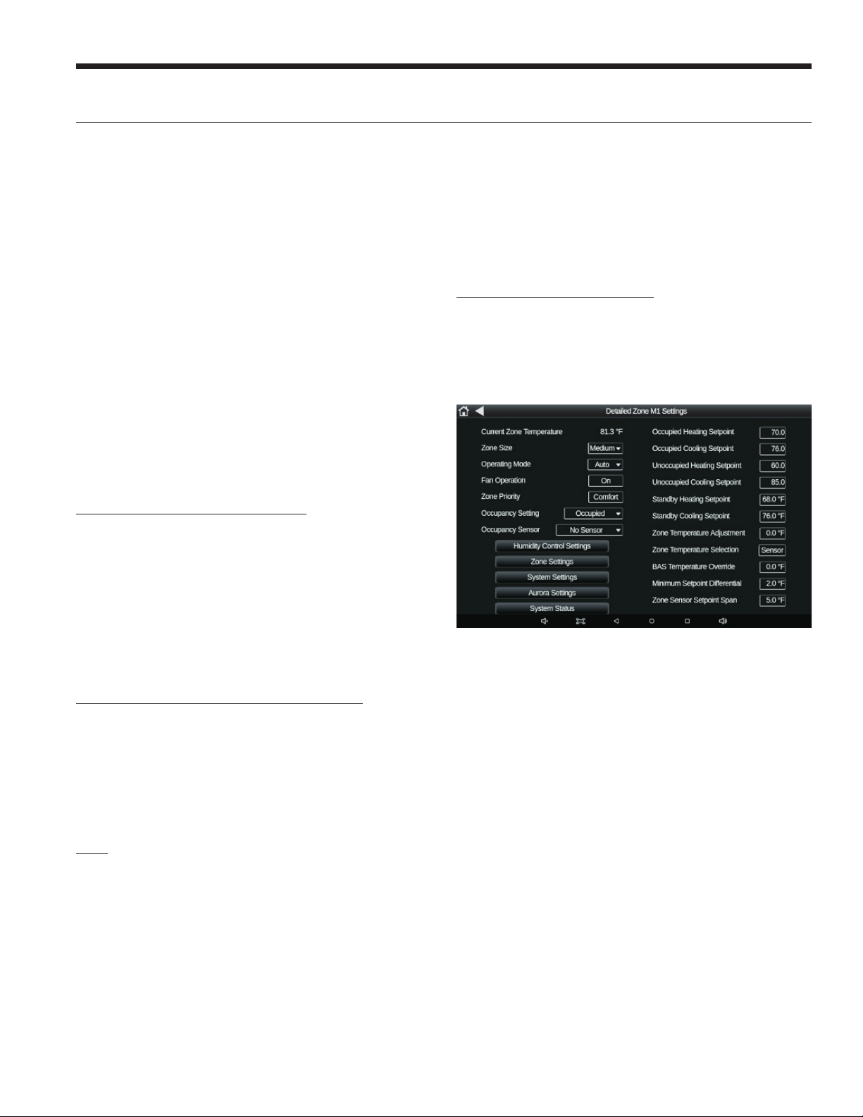
Detailed Zone Settings
Each zone in the system will have a Detailed Zone Settings
screen that can be accessed from the main Zone Settings
screen. Each Detailed Zone Settings screen can be used
to adjust the same settings available on the Zone Settings
screen, as well as modifying occupancy, setpoint, and tem-
perature sensor settings.
Occupancy Setting
The occupancy setting selections determines what space
conditioning setpoints will be used for the zone. Each zone
may be individually configured to either be Occupied, Un-
occupied, Temporarily Occupied, or Standby.
Occupancy Sensor
The occupancy sensor setting is used to select if the zone
has an occupancy sensor, and if so, what it’s function will
be.
No Sensor – When configured for “No Sensor”,
even if an occupancy sensor is connected it will
not be used to control the occupancy of the
zone.
Occupied Sensor – When configured for “Oc-
cupied Sensor”, an active occupancy sensor
will put the zone into the occupied mode if it
is currently unoccupied by either command or
schedule.
Temp Occupied Sensor – When configured for
“Temp Occupied Sensor”, an active occupancy
sensor will put the zone into the temporary
occupied mode if it is currently unoccupied by
either command or schedule.

16
INTELLIZONE2 BACNET INSTALLATION MANUAL
IntelliZone2 BACnet Configuration/Diagnostics cont.
Standby Sensor – When configured for “Standby
Sensor”, an active occupancy sensor will put the
zone into the occupied mode if it is currently in
standby by either command or schedule.
Occupied Setpoints
The Occupied Heating Setpoint and Occupied Cooling
Setpoint values are used when the zone is in the occupied
or temporary occupied mode either by command,
schedule, or override.
Unoccupied Setpoints
The Unoccupied Heating Setpoint and Unoccupied
Cooling Setpoint values are used when the zone is in the
unoccupied mode either by command or schedule.
Standby Setpoints
The Standby Heating Setpoint and Standby Cooling
Setpoint values are used when the zone is in the standby
mode either by command or schedule.
Zone Temperature Adjustment
The zone temperature adjustment value is used as a
calibration or offset value for the Rnet sensor for the zone.
Zone Temperature Selection
The zone temperature selection is used to choose between
using the temperature value from a connected Rnet zone
sensor, or a zone temperature supplied from the BAS
system.
BAS Temperature Override
The BAS temperature override value is the zone
temperature value to be used when the Zone Temperature
Selection is set to BAS.
Minimum Setpoint Differential
The minimum setpoint differential is the minimum allowed
value between the heating and cooling setpoints for the
zone.
Zone Sensor Setpoint Span
The zone sensor setpoint span is the amount of adjustment
allowed at the Rnet zone sensor when and appropriate
sensor is used, and the adjustment is allowed.
Humidity Control
The Humidity Control screen allows the settings for
humidity control of the system to be set. Humidity control
settings are system wide, not set individually for each zone.
Humidity Control
Humidity Control
The humidity control selection determines what type of
humidity control, if any the system will use.
None – When configured for “None” the
system will not adjust operation for either
dehumidification or humidification.
Dehumidification Only – When configured for
“Dehumidification Only” the system may adjust
operation based on the current system humidity
value and active dehumidification setpoint.
There will be no system humidifier output
generated for humidification operation.
Both – When configured for “Both” the
system may adjust operation based on the
current system humidity value and active
dehumidification setpoint for dehumidification
operation and may activate the system
humidifier output based on the current system
humidity value and active humidification
setpoint for humidification operation.
Humidification Only – When configured for
“Humidification Only” the system may activate
the system humidifier output based on the
current system humidity value and active
humidification setpoint. System operation will
not be adjusted for dehumidification.
Occupied Setpoints
The Occupied Dehumidification Setpoint and Occupied
Humidification Setpoint values are used when the zone
is in the occupied or temporary occupied mode either by
command, schedule, or override.
Unoccupied Setpoints
The Unoccupied Dehumidification Setpoint and
Unoccupied Humidification Setpoint values are used when
the zone is in the unoccupied mode either by command or
schedule.

17
INTELLIZONE2 BACNET INSTALLATION MANUAL
IntelliZone2 BACnet Configuration/Diagnostics cont.
Damper Limit Settings
The Damper Limit Settings screen allows a maximum and
minimum position setting for each zone in the system.
Minimum Position
The minimum position settings for each zone should be set
to 0% in most cases. The only exception should be to meet
absolute minimum air delivery requirements. Setting the
minimum damper position to anything other than 0% can
cause over-cooling or over-heating of the zone reducing
the overall system comfort level.
Maximum Position
The maximum position settings for each zone are typically
set to 100%. These values may be reduced to help balance
the airflow delivered to various zones if needed.
Demand Ventilation
The Demand Ventilation screen shows the current
operating status for demand–controlled ventilation, as well
as the settings to configure the operation.
Demand Controlled Ventilation
The demand–controlled ventilation setting is used to enable
or disable the DCV operation, which controls an outside air
damper based on the system air quality.
DCV Control Variable
The DCV control variable setting is used to select between
using CO2 or VOC as the air quality value to control the
DCV operation.
DCV Minimum Damper Position
The DCV minimum damper position setting is the damper
position associated with the DCV Low PPM Setting Value.
The DCV minimum damper position is normally set to
provide the minimum required outside air.
DCV Maximum Damper Position
The DCV maximum damper position setting is the damper
position associated with the DCV High PPM Setting Value.
DCV Low PPM Setting Value
The DCV low PPM setting value setting is the air quality
PPM value associated with the DCV Minimum Damper
Position.
DCV High PPM Setting Value
The DCV high PPM setting value setting is the air quality
PPM value associated with the DCV Maximum Damper
Position.
Internal Schedule
The Internal Schedule screen allows the internal XPC
occupancy schedule associated with each zone to be
selected and edited. On this screen the Schedule Object
number is the zone number the schedule is associated with.
Individual Zone. When an individual zones internal schedule
is selected, it may be viewed as a monthly or weekly
schedule. For either display type, individual days may
then be selected and the start / stop times for occupied
operation may be adjusted.

18
INTELLIZONE2 BACNET INSTALLATION MANUAL
IntelliZone2 BACnet Configuration/Diagnostics cont.
Manual Overrides
The Manual Overrides Screen allows manual operation
of the heat pump system as well as the individual zone
dampers.
NOTE: For any manual operation the System Override
Setting must be set to “Manual”. If Normal damper
operation is selected when the system is set for manual
operation, the system will open all dampers and operate in
the central zone mode.
When the manual mode is active, each component
(Compressor, Blower, VS Pump) may either be allowed
to operate automatically based on system conditions or
the operation of other outputs, or they can be manually
controlled individually. For example, if manual compressor
operation is selected, the compressor speed would be
based on the manual setting, but the blower and VS pump
could be allowed to operate automatically based on the
currently selected compressor speed.
Aurora Settings
The Aurora Settings screen allows most Aurora settings
that are typically set using an AID tool to be set using the
tablet interface.
Network Commands
The Network Commands screen displays settings that are
typically set or controlled by the BAS. The values may be
changed using this screen, but if the BAS is actively writing
to the point, the value from the BAS will override any
adjustments made on this screen.
OAT Value Source Config
The OAT value source config value selects between the
BAS and the zone panel as the source for the system
outdoor air temperature value.
BAS OAT Override Value
The BAS OAT override value is the system outdoor
temperature value used if the OAT Value Source Config
value is set to BAS.
BAS Humidity Override Value
The BAS humidity override value is the system humidity
value used if being supplied by the BAS.
BAS CO2 Override Value
The BAS CO2 override value is the system CO2 value used
if being supplied by the BAS.
BAS VOC Override Value
The BAS VOC override value is the system VOC value used
if being supplied by the BAS.
System Status
The System Status screen displays the current operating
conditions of the overall system, including zone
configurations and demands along with the current heat
pump operating status.

19
INTELLIZONE2 BACNET INSTALLATION MANUAL
IntelliZone2 BACnet Configuration/Diagnostics cont.
Aurora Conditions
The Aurora Conditions screen displays the current
operating status of the heat pump system, with many of
the main diagnostic values.
Additional Aurora Data
The Additional Aurora Data screen displays additional
diagnostic information on the heat pump and Aurora
control system.
Aurora Timers / Details
The Aurora Timers / Details screen displays the
current Aurora timer values as well as the status of the
communicating components in the system, fault codes, and
the current software revision of each control.
Aurora Control Signals
The Aurora Control Signals screen displays the current
status of the primary control inputs and main outputs of
the Aurora control system.

20
INTELLIZONE2 BACNET INSTALLATION MANUAL
IntelliZone2 BACnet Configuration and Wiring
Each zone may have either one or two Rnet sensors, or the zone temperature may be provided by the BAS. If more than
one Rnet sensor is used for a single zone, the values from the two sensors will be averaged to be used for the effective
zone temperature.
Rnet Sensor Wiring
For best results Rnet zone sensors should be wired in a daisy chain configuration using (2) 18AWG twisted pair unshielded
communication cables. One twisted pair should be used for the 12v supply and ground wire connections and the other
twisted pair should be used for the Rnet+ and Rnet- connections.
Rnet Sensors Wired in Daisy Chain Configuration
Rnet Sensor Addressing
Each Rnet zone sensor is addressed using the DIP switch on the back of the ZS sensor. Each sensor in the system must
have a different address, and unique pre–defined addresses have been assigned for each zone. If only one sensor is used
for a zone, it may use either of the two addresses defined for that zone.
Note: Only one Rnet zone sensor with a CO2 or VOC option may be used per system.
DIP Zone 1 Zone 2 Zone 3 Zone 4 Zone 5 Zone 6 DIP
DIP 1 Off Off On On Off Off On On Off Off On On DIP 1
DIP 2 Off Off Off Off On On On On Off Off Off Off DIP 2
DIP 3 Off Off Off Off Off Off Off Off On On On On DIP 3
DIP 4 Off On Off On Off On Off On Off On Off On DIP 4
1 2 3 4
Table of contents
Other Water Furnace Temperature Controllers manuals


