manuals.online logo
Brands
  1. Home
  2. •
  3. Brands
  4. •
  5. Powtier Controls
  6. •
  7. Temperature Controllers
  8. •
  9. Powtier Controls TC308 User manual

Powtier Controls TC308 User manual

TC308
LOW COST TWO TERM DIGITAL DISPLAY
TEMPERATURE CONTROLLER
INSTRUCTION MANUAL
CONTENTS
DESCRIPTION..........................................................2
INSTALLATION.........................................................2
CONTROL ADJUSTMENTS.....................................3
TUNING.....................................................................3
TECHNICAL SPECIFICATION.................................5
ORDERING INFORMATION.....................................5
SUPPLIER INFORMATION......................................5
TC308 Instruction Manual Powtier Controls Limited
DESCRIPTION
The TC308 is housed in a durable sheet metal and
flame retardent plastic housing. The seven segment
LED display monitors measured value continuously
and the error bar indicator shows the proximity to
setpoint.
Setpoint can be displayed by depressing the setpoint
changeover switch on the front panel. The setpoint,
proportional band and manual reset controls are
located at the front and concealed behind a snap-
shut door to minimise any accidental re-setting.
Setpoint adjustment is made by turning the setpoint
thumbwheel.
Dimensions
INSTALLATION
The instrument requires a 92X92mm panel cut out
and is fixed by retainers positioned on the top and
bottom of the instrument. Maximum panel thickness
is 10mm.
All external wiring is made to the rear of the
instrument via M3 screw terminals.
Wiring diagram.
22 November 1994 - 2 - 308IM
Issue 2.0
TC308 Instruction Manual Powtier Controls Limited
CONTROL ADJUSTMENTS
PROP. BAND - Proportional Band adjustor gives Xp
of 1% to 10% of span is located at the front and
concealed behind the snap-shut door.
MAN. RESET - Manual Reset adjustor removes the
steady state error inherent in PD control; it is located
at the front and concealed behind the snap-shut
door.
HIGH ALARM (option) - gives relay change-over
when the measured temperature exceeds the high
alarm limit at or above setpoint and is settable by
means of P1 - located on top of the instrument.
LOW ALARM (option) - gives relay change-over
when the measured temperature falls below the low-
alarm limit at or below setpoint and is settable by
means of P2 - located on top of the instrument.
BAND ALARM (option) - gives relay change-over
when the measured temperature falls outside the
high and low alarm limits; these are settable by P1 -
band high limit; and P2 - band low limit; both located
on top of the instrument.
HEAT (OR COOL) CYCLE TIME - the time-
proportioning output cycle time is adjustable between
4 and 20 seconds
Control adjustments.
TUNING
1. Set Man. Reset to fully counter clockwise (zero).
2. Set Prop. Band to mid-position (>5%).
3. Set P3 to fully clockwise to give maximum output
cycle time.
4. Set setpoint to desired working temperature.
5. Observe the response of the measured
temperature.
If temperature overshoot occurs, but eventually
decays to a steady temperature below setpoint - then
to reduce overshoot, turn Prop. Band adjustor
clockwise to increase the proportional band.
If continuous oscillations occur at around setpoint
temperature, turn Prop. Band adjustor clockwise to
increase proportional band until oscillations cease.
If the measured temperature settles at a temperature
below setpoint and without overshoot - then turn
Man. Reset adjustor clockwise until measured
temperatureeventually equals setpoint temperature.
If continuous oscillations occur at below setpoint
temperature, adjust P3 couter-clockwise to reduce
output cycle time until oscillations cease.
If the measured temperature remains below the
setpoint when the Man.Reset is alaready at its
maximum (fully clockwise), then turn the Prop. Band
adjustor counterclockwise (reducing the proportional
band) to reduce the steady-state error.
22 November 1994 - 3 - 308IM
Issue 2.0
TC308 Instruction Manual Powtier Controls Limited
TECHNICAL SPECIFICATION
INPUT
Thermocouple Standard ASTM E230, BS4937
DIN 43710.
Cold junction Automatic.
Compensation
Thermocouple break Upscale (heat O/P) or
protection downscale (cool O/P) fitted
as standard;
display shows -.-.
Resistance Thermometer Lead resistance error is
2 or 3 wire automatically reduced
by using 3 wires.
RTD (Pt 100) BS 1904, DIN 43760.
OUTPUTS
Relay 5A resistive at 230V rms.
Logic output Non-isolated 10mA 12V dc.
Triac output 1A or 13A at 230 Vrms.
Power feedback To stabilise output against
line voltage variation.
CONTROL
PD control Proportional and derivative.
Proportional band Xp 1% to 10% of span.
Self-adjusting prop. Bnad 0.5% to 10% when setpoint
at span; 2% to 20% when
setpoint at mid-span.
Derivative time td 4 to 20 seconds, correspond
to heat cycle time.
Manual reset 0 to 50% output power at
span.
ALARM OUTPUTS OPTIONS
Relay 2A resistive at 230 Vrms.
High alarm 0 to 20% of span.
Low alarm 0 to 20% of span.
Band alarm 0 to 20% of span.
ENVIRONMENTAL
Supply voltage 115/230V +/-15% 50/60Hz
100/200V +10% -15%
50/60Hz.
Operating temperature 0 to 50 Deg.C.
PERFORMANCE
Indication accuracy Better than 0.5% of span
+/-1 digit.
Supply voltage variation Negligible effect.
GENERAL
Display digit 3 or 31/2 digits.
Display 7 segment and negative
sign display; digit size
13mm height by
7.4mm width.
Error indication 3 LED display; upper LED
+1% of span, lower LED
-1% of span.
Dimensions 96x96x125mm.
Panel cut out dimensions 92x92mm.
Weight 750g maximum.
Power consumption 6VA maximum.
ORDERING INFORMATION
You are welcome to order by description or code.
308 - - - - - - 00
INPUT...................|.........|.........|.........|.........|.........|
SCALE............................|.........|.........|.........|.........|
OUTPUT..................................|.........|.........|.........|
SUPPLY VOLTAGE............................|.........|.........|
OPTIONS.....................................................|.........|
END OF CODE......................................................|
INPUT
Iron-Constantan (J) BS
-50 to 500 10
Fe-Konst (J) DIN
-50 to 500 30
Chromel Alumel (K)
-50 to 500 20
0 to 999 23
0 to 1200 21
Resistance Thermometer (PT100)
-50 to 200 40
SCALE
Degree Celsius .........C
Degree Fahrenheit.....F
OUTPUT
Heat (or cool) output
relay................................10[or 11]
logic................................20[or 12]
triac 1A...........................30[or 13]
triac 13A (3KW)..............40[or 14]
SUPPLY VOLTAGE
115/230V +/-15% 50/60Hz..............1
100/200V +10% -15% 50/60Hz.......2
OPTIONS
Alarm
low deviation............................................21
high deviation..........................................22
END OF CODE......................................................00
Please consult Sales office for other possible options
and scales.
ORDER EXAMPLE:
ATC308 with J-type thermocouple input, scaled -50
to 500 °C, relay heat output, operating at 230V and
without any option will have the code:-
308-10-C-10-1-00.
SUPPLIER INFORMATION
Powtier Controls Limited
Unit 4, Parkland Business Centre
Chartwell Road, Lancing
West Sussex BN15 8UE England
Tel: +44(0)1903 750800
Fax: +44(0)1903 750678
Email: Email@PowtierControls.co.uk
22 November 1994 - 4 - 308IM
Issue 2.0

Other Powtier Controls Temperature Controllers manuals

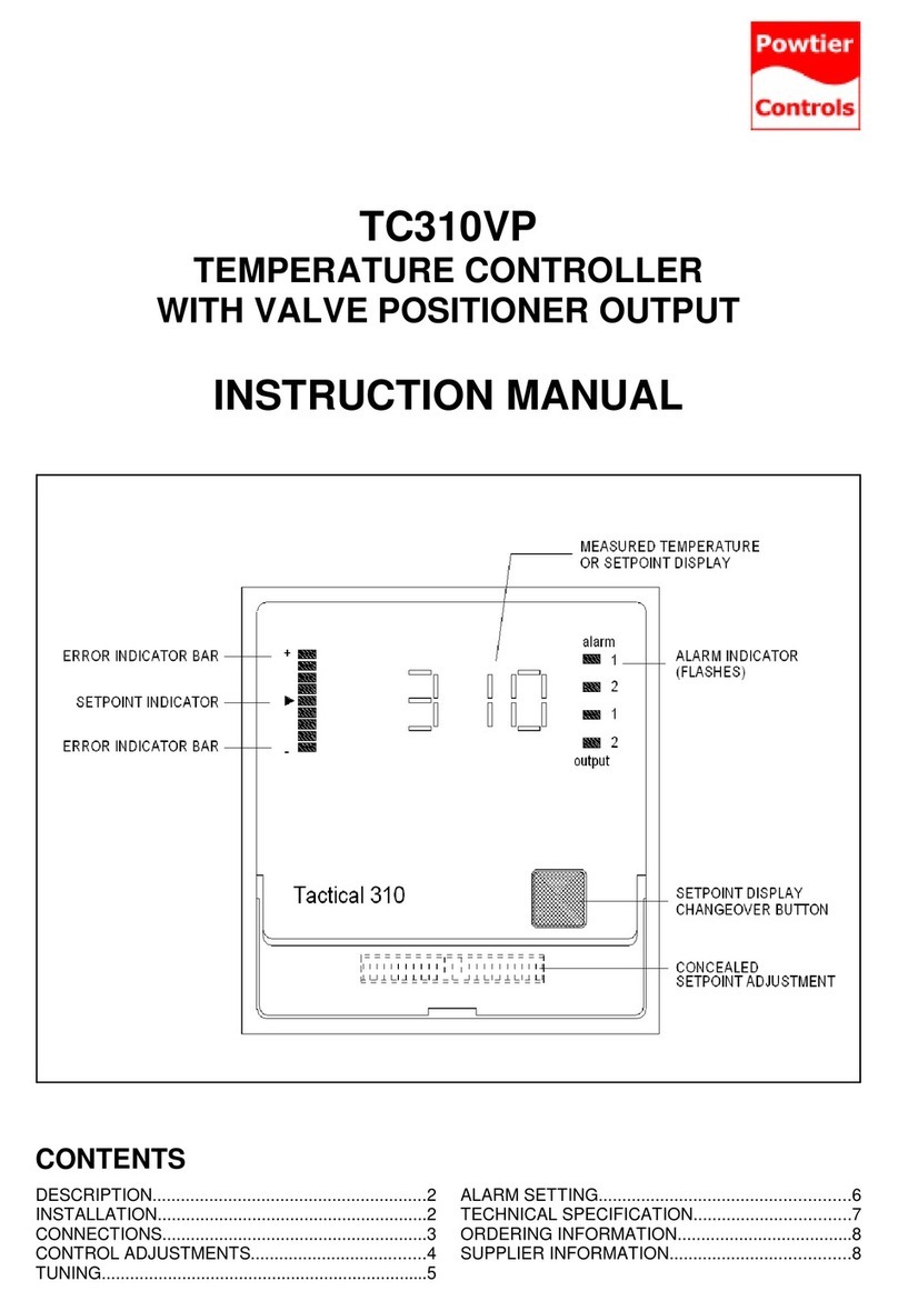
Powtier Controls Tactical 310 User manual

Powtier Controls

Powtier Controls Tactical 310 User manual

Powtier Controls ACC-6-00 User manual

Powtier Controls

Powtier Controls ACC-6-00 User manual

Popular Temperature Controllers manuals by other brands

AEC TDH-6 Series Operation and installation manual

AEC

AEC TDH-6 Series Operation and installation manual

Velleman VELBUS VMB1TSW manual

Velleman

Velleman VELBUS VMB1TSW manual

Omron E5CZ user manual

Omron

Omron E5CZ user manual

Pentair Raychem RTD7AL installation instructions

Pentair

Pentair Raychem RTD7AL installation instructions

Oregon Scientific THC-268 user manual

Oregon Scientific

Oregon Scientific THC-268 user manual

Comelit Home 20004100 Technical manual

Comelit

Comelit Home 20004100 Technical manual

Raypak Temp-Tracker Installation & operating instructions

Raypak

Raypak Temp-Tracker Installation & operating instructions

Domotec Frost-Control DHB 360 C Installation notes

Domotec

Domotec Frost-Control DHB 360 C Installation notes

elsner elektronik KNX eTR 101 Technical specifications and installation instructions

elsner elektronik

elsner elektronik KNX eTR 101 Technical specifications and installation instructions

Omron EJ1 EtherCAT user manual

Omron

Omron EJ1 EtherCAT user manual

IVT PRINETO manual

IVT

IVT PRINETO manual

AKO AKO-16523 user manual

AKO

AKO AKO-16523 user manual

CSI HMP155A instruction manual

CSI

CSI HMP155A instruction manual

Vaillant VRT 50 Operating and installation instructions

Vaillant

Vaillant VRT 50 Operating and installation instructions

Binder MKF 115 operating manual

Binder

Binder MKF 115 operating manual

CCL ELECTRONICS C3127A user manual

CCL ELECTRONICS

CCL ELECTRONICS C3127A user manual

Viessmann VITOTROL 100 Installation and service instructions

Viessmann

Viessmann VITOTROL 100 Installation and service instructions

Phason SSC-1D installation guide

Phason

Phason SSC-1D installation guide

manuals.online logo
manuals.online logoBrands
  • About & Mission
  • Contact us
  • Privacy Policy
  • Terms and Conditions

Copyright 2025 Manuals.Online. All Rights Reserved.