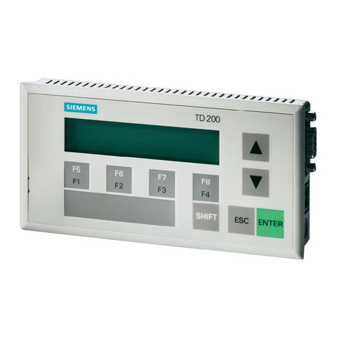
Water-Loo Smart Panel User manual

© Waterloo Biofilter Systems 2019
Smart Panel
Owner’s Manual
Waterloo Biofilter Systems Inc.
143 Dennis Street, PO Box 400
Rockwood ON N0B 2K0
Tel: 519-856-0757 Fax: 519-856-0759
1-866-366-4329
info@waterloo-biofilter.com
www.waterloo-biofilter.com

Page | 2
Owner’s Manual
Table of Contents
Table of Contents......................................................................................................................................2
Alarms .........................................................................................................................................................3
Main Display...............................................................................................................................................4
Customer Menu ........................................................................................................................................5
How to Perform Function Test ...............................................................................................................6
How to use Manual Mode.......................................................................................................................7
Check Active Inputs ..................................................................................................................................8

Page | 3
Owner’s Manual
Alarms
Your control panel is equipped with audible and visual alarms. When the alarm goes off you
will hear a loud buzzer sound and the light on top of the control panel will turn on.
Why is the alarm going off?
The alarm indicates that the water level in the pump tank or Biofilter is too high.
What should you do?
You should call your maintenance provider immediately. Limit water use until the problem
has been corrected.
How do I silence the alarm?
Press the ESC key on the panel face to silence to alarm.
Remember that this does NOT mean the problem has been solved, you will still need to
contact Waterloo Biofilter or your service provider to rectify the situation.

Page | 4
Owner’s Manual
Main Display
1. Outputs
Displays active and Inactive. In the picture above Outputs 1 is Active (shaded) and Output 2
is inactive. Depending on the number of outputs connected to the panel, the display will
change. When an output is active, the timer counts down how long until it is deactivated.
When the output is inactive, the timer counts down how long until it is activated.
2. Inputs
Displays whether Inputs 1 to 4 are active. Shaded Inputs are active.
3. Current Readings
The current draw in amperage of an active output is displayed here. For panels with more
than 5 outputs, current sense will be displayed on a separate screen.
4. Cellular Connection
Connection to the server is displayed on the screen by a cell tower icon.
5. Cellular Signal Strength
The strength of the cell signal is displayed here. Panel automatically determines best carrier
to use based on signal strength.
6. Date / Time
The date is displayed in DD.MM.YY format.
7. Time
The user can select a 12 HR or 24 HR clock in the Date / Time menu.
8. Interface Buttons
Keys to navigate around the control panel interface
Key
Description
Confirm selection
Cancel selection / Go back to previous screen
Scroll Down / Decrease number
Scroll Up / Increase number
Right / Shift character to Right
Left / Shift character to Left

Page | 5
Owner’s Manual
Customer Menu
The Customer Menu gives access to the basic functions of the control panel. This section is
accessed by pressing the Down arrow on the main screen.
Device Information
General information regarding the device. Includes Firmware version, Serial Number,
Variant information and production date.
Function Test
Function Test allows a user to perform a quick run through all the outputs to verify proper
operation and amperage readings. The cycle will run through all enabled outputs by
sequence, test the alarm and check the backup battery status.
Manual Mode
Allows operator(s) to temporarily run a specified output for a period of time. The time of
this run is predetermined at time of construction.
Operation Time
Breakdown of the Operation Time for all outputs. Operation time is broken down by
calendar weeks.
Date / Time
Allows user to change date and time settings.
Display
Allows user to modify Contrast, Brightness and Illumination settings.
Language
Choose language of operation.
Restart Panel
Performs a software restart of the panel.

Page | 6
Owner’s Manual
How to Perform Function Test
Function Test allows a user to perform a quick run through all the outputs to verify proper
operation and amperage readings. The cycle will run through all enabled outputs by
sequence, test the alarm and check the backup battery status.
Once the user has accessed the Customer Menu, scroll Down to Function Test and
Press OK
Scroll down to Start Test and press OK . A pre-set delay will start counting down
and the first Active output will turn ON.
The output will turn ON for the duration of the predetermine cycle. During this cycle the
current of the output will also be displayed at the bottom of the screen.
If the user wishes to skip the output, or go ahead and move to the next output, OK can
be pressed and the remaining cycle time for that output will be skipped. At the end of the
Function Test cycle the visual/audio alarms, as well as the backup batteries will be tested.

Page | 7
Owner’s Manual
How to use Manual Mode
Manual Mode allows operator(s) to temporarily run a specified output for a period of time.
The time of this run is predetermined at time of construction.
Once the user has accessed the Customer Menu, scroll Down to Manual Mode and
Press OK
In the Manual Mode menu scroll down to the Output you would like to control, Press OK
to select.
Choose between Automatic, Always ON and Always OFF modes by scroll UP or Down.
Automatic uses the predetermine settings of the Output. Always ON, Always OFF
enables/disables the Output for a period of time, set by the manual run time setting. Once
the Mode has been chosen, Press OK to enable. Press ESC to exit the Manual Mode Menu.

Page | 8
Owner’s Manual
Check Active Inputs
Active Inputs can be check on the Main Screen of the panel. Near the bottom of the screen
Inputs display whether Inputs 1 to 4 are active. Shaded Inputs are active.
If there are more than 4 inputs in the control Panel the input screen needs to be accessed
to verify the status of the remaining inputs. To access the Input screen, press the UP
button while on the main screen.
Table of contents
