Water Powered Technologies Papa Pump User manual

a great UK
design
patented design
Owner’s Manual
Installation, Operation and Maintenance Guide
patented desig
n

Index
3
4
5
6
7
11
14
15
17
18
19
21
24
25
29
33
page no. description
Kit contents
About the Papa pump
Papa technology
How the Papa pump works
Installation principles
Catchment tank details & installations
Supply tank details and installation
Pump chamber details and installation
Multiple installations
Reference charts
Seradisc filter
Installation & commissioning
Pump parts list
Pump maintenance
Troubleshooting
Specifications
2
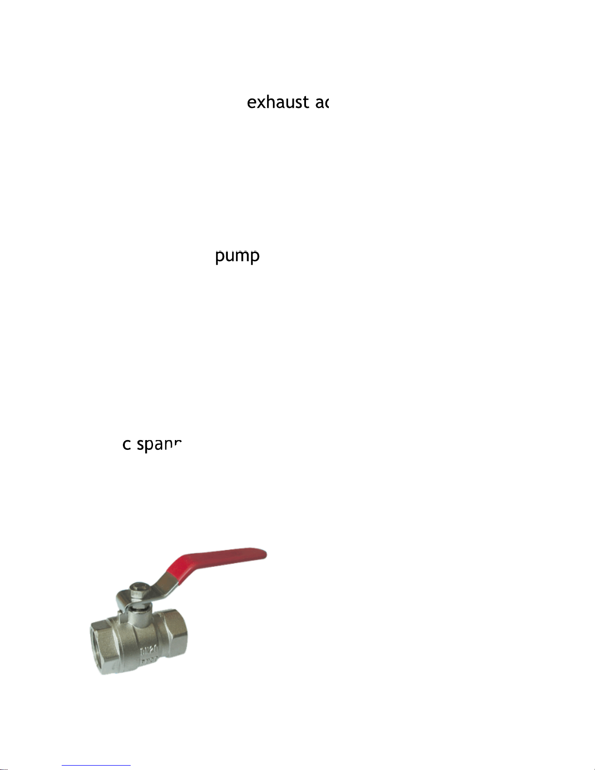
Kit Contents
exhaust adaptor
pump
hose assembly
c spanner
Seradisc filters
x 2
spare set valves
2” ball valve
3
pressure vessel
exhaust adaptor
pum
p
c spanner
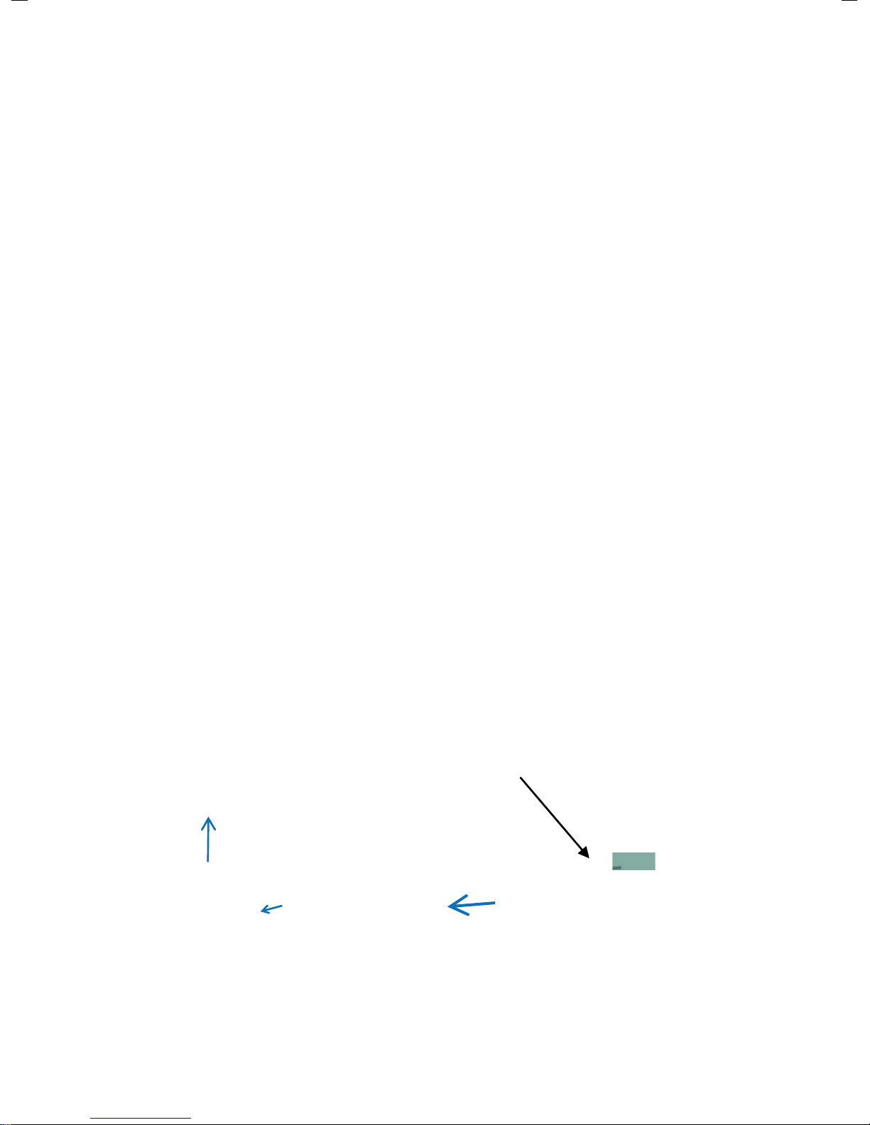
About the Papa pump
Water Source
a typical schematic layout for a Papa Pump system
B
A
C
A: Catchment Tank
B: Supply Tank
C: Pump Chamber
D: Water Storage
D
Flow
Water powered pumping traditionally goes back 1000’s of years where it was
used primarily for low head irrigation. More recently, from the late 1700’s
hydraulic ram pumps were developed as an efficient and effective means of
transporting water over long distances and great heights where they have been
utilised to provide water in most parts of the world prior to the advent of
‘previously inexpensive’ mains water and electricity supplies.
Developed within the UK in the mid-90s, the Papa Pump represents a modern,
smaller, lighter and more effective alternative and is used in many countries to
provide water for a wide variety of uses. With the addition of the revolutionary
composite version, Papa continues to ensure that your water transport
requirements are cost-effective and delivered in a reliable and sustainable
system.
Simple water power
By utilising a naturally flowing water source, the Papa pump is able to transport
up to 30% of that water to the desired location, allowing the residual water to be
returned to the natural source. With minimal maintenance and zero fuel costs
and emissions, the Papa Pump will provide you with a clean and efficient system
for your water transportation requirements including agriculture, horticulture,
irrigation, domestic and industrial use.
4

Papa technology
exhaust
port
delivery
port supply
port
main valve
non-return
valve
5
adjuster
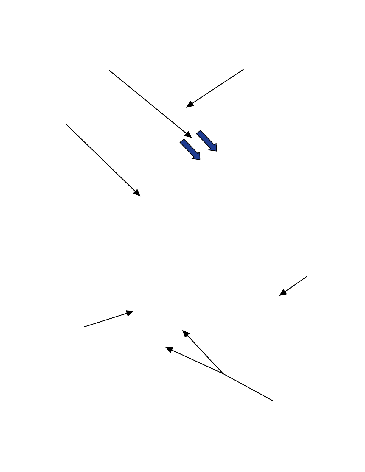
How the Papa pump works
Water enters pump via supply port and flows around main valve to exhaust port.
As the flow increases around the main valve a differential pressure occurs
causing the valve to suddenly close. The flow and mass of water is then directed
through the non-return valve and into the delivery port at a higher pulsed
pressure. This pressure suddenly reduces causing the main valve to reopen and
the cycle repeats.
Turning the adjuster to open the valve allows flow through the pump to be
regulated so that a greater flow generates a greater pressure and water delivery.
6

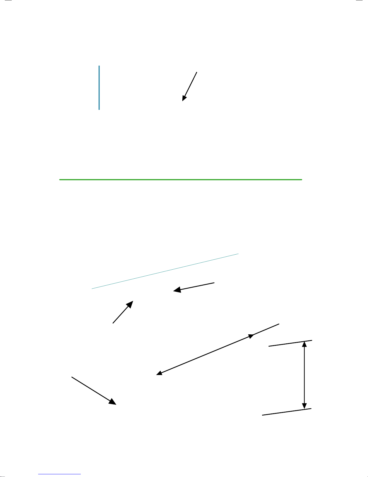
Installation principles
A natural water source is required
river
stream
spring
pond/lake
7

catchment
tank
supply
tank
pump
chamber
water source flow
Plan Elevation
Side Elevation
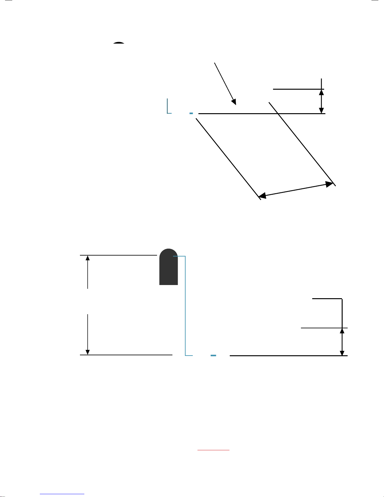
MORE SUPPLY HEAD = MORE WATER!
Supply
Head
Delivery
Head
catchment
tank
pump
chamber
supply
tank
storage tank
SH
DH
The greater the supply head, the more efficient
the pump is!
8

Supply Head greater
than 2 metres
SH
Site Layout Overview
MORE SUPPLY HEAD = MORE WATER!
A minimum Supply Head of 2 metres is required, but please
ensure that the maximum head is achieved for best results
9
delivery pipe
storage tank
catchment
tank
pump
chamber
supply
tank
feed pipe feed pipe
overflow
pipe
supply
pipe
NOTE! Check that the Delivery Head (DH) does not exceed the pressure rating of
pipes!
The maximum Delivery Head (DH) is 30 x the Supply Head (SH)
Delivery Head DH
= max 30 x SH
Supply Head
SH
10
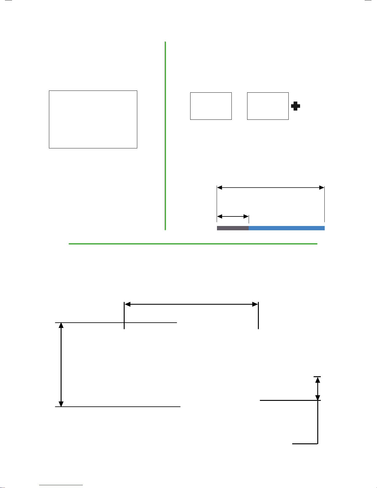
Supply Head
SH
L
Supply Pipe length
NOTE! The PAPApump can operate outside of these
parameters but the performance will be affected
Supply Pipe
length
L = 4-7 x SH
Supply Pipe
The Supply Pipe length (L) should be between 4-7 x the Supply Head (SH) for
optimum efficiency and pressure
catchment
tank
feed pipe
supply
tank
Feed Pipe should be straight with a low gradient (1:500) into the Supply Tank, but
check pipe friction chart to establish the most suitable size and gradient.
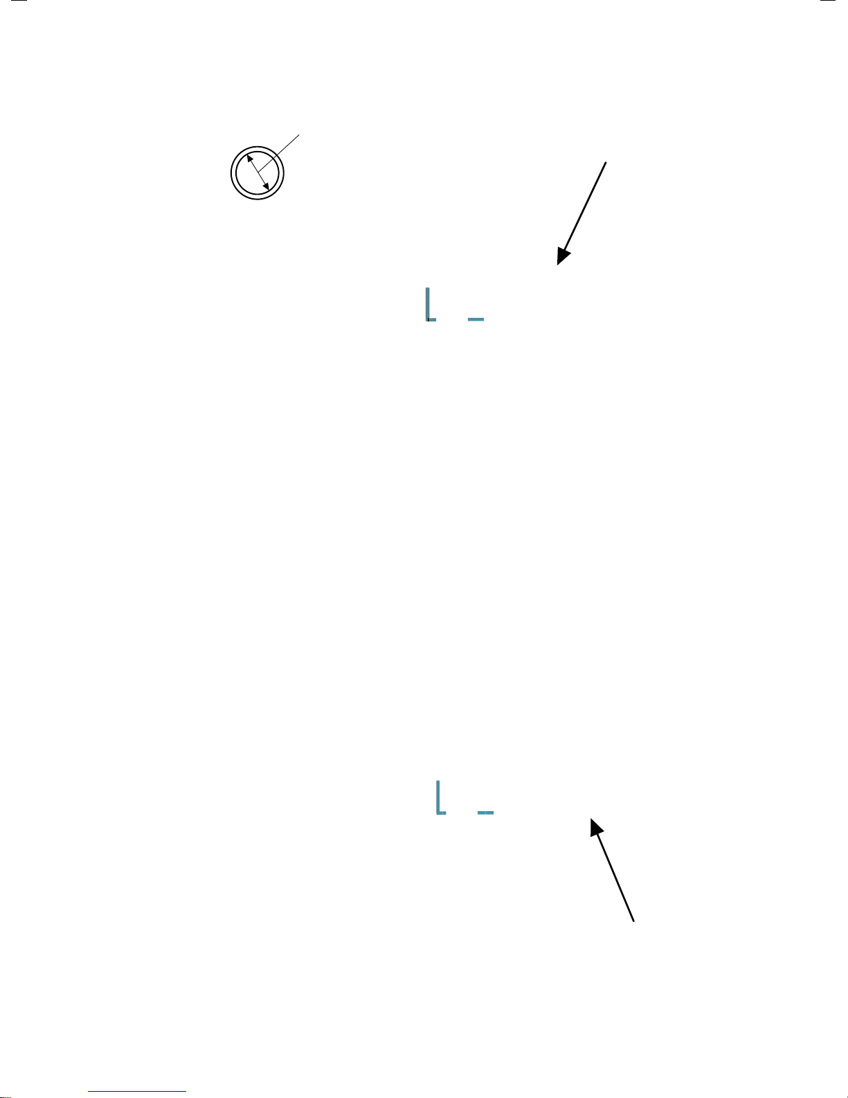
Catchment Tank details & installations
Catchment method 1
feed pipe
water flow
90 deg bend facing
downstream
1 metre
min
1 metre
min
11
Catchment method 2
feed
pipe
water ingress through
holes drilled in tank stones used as
coarse filter
feed pipe
inlet from
water source
Seradisc filters
Catchment tank
NOTE! The more Seradisc filters fitted, the better the reliability of the system
12
Feed Pipe
Overflow Pipe
NOTE! Larger diameter pipe may be required for multiple pump installations with
more than 2 pumps.
Overflow Pipe
13
4”
Feed Pipe
or
100mm
NOTE! Larger diameter pipe may be required for multiple pump installations with
more than 2 pumps. Please refer to friction chart. Add more Seradisc filters
accordingly

Supply Tank details & installations
feed pipe
supply pipe
overflow pipe
socket
Seradisc filter
Supply Tank
1 metre
min
1 metre
min
removable stand
pipe (used for draining
down)
Supply Pipe -1
supply pipe
2” (50mm)
Galvanised steel
or MDPE
(see next page)
14
Supply Pipe - 2
min 1/3 supply pipe length
galvanised into pump
supply pipe length
or
MDPE
either use
do not use
100% MDPE
use 100% Galvanised steel
IF DELIVERY HEAD (DH)
IS LESS THAN 15m IF DELIVERY HEAD (DH)
IS MORE THAN 15m
or
Pump Chamber details & installations
Pump Chamber
supply pipe
overflow
pipe
delivery
pipe
150mm min( allows pump to be rotated inside chamber)
1m
1m
15

Pump Chamber
Note: Chamber requires a cover if a Sureflow flow valve is fitted
supply pipe
overflow
pipe
tank drain
delivery
pipe
ball valve
pump support
nr valve
NOTE! 2 pumps can be installed in a 1m diameter ring.
Larger rings will be required for additional pumps
Delivery Pipe
NOTE! The diameter of the delivery pipe may vary depending on the number of
pumps and distance. Please refer to the pipe friction chart for the appropriate size
delivery
pipe
25mm
16

Multiple pump installations
Typical dual pump installation
delivery
pipe
feed
pipes
support
pumps
NOTE! Please check delivery pipe size by referring to the pipe friction chart
when using multiple pumps or pumping over long distances.
Manifolded multiple pump installation
17
delivery
pipe manifold
delivery
pipe
feed
pipes
NR valve

18
Pump performance chart

19
seradis TM
Installation methods and performance details
NOTE! The more Seradisc filters fitted, the better the reliability of the system
cut 2 ¼” dia. holes in pipe
and screw in filters
use flexible coupling
supplied with filter
Note: Particulate sizes are calculated. Due to the flexible nature of the discs,
Seradisc filters fitted with lower numbers of discs may allow ingress of
particulates slightly larger than as indicated on the graph.
0
200
400
600
800
1000
1200
1400
1600
1800
12 34 5
litres/min
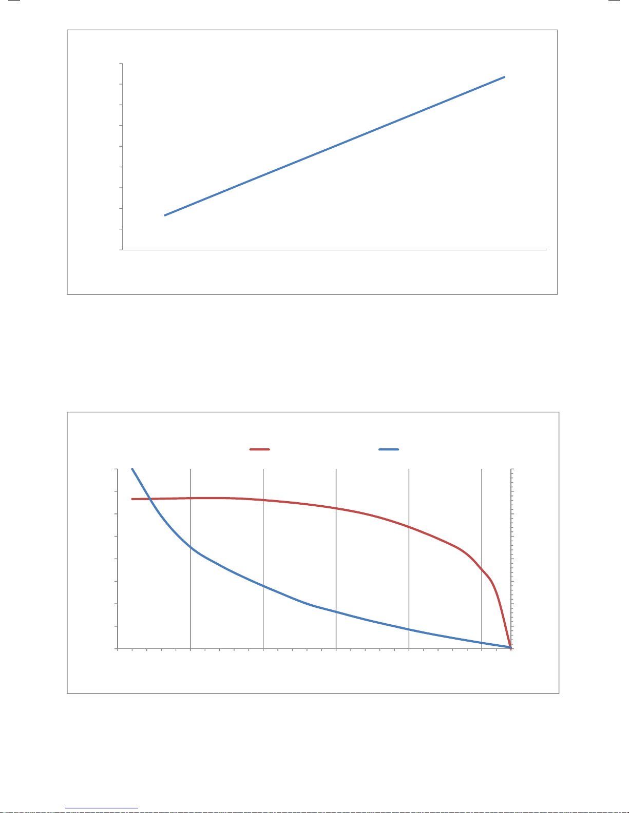
no. of filters in parallel
Flow through standard 16-disc filters in parallel configuration
0
0.5
1
1.5
2
2.5
3
3.5
4
0
50
100
150
200
250
300
350
400
15 20 25 30 35 40
particulate size (mm)
litres/min
no. of discs in filter assembly
Flow through filter and particulate screening
filters in parallelf ilters in series
flow particulate size
20
Table of contents
Popular Water Pump manuals by other brands


Annovi Reverberi
Annovi Reverberi AR 713 instruction manual

KNF
KNF NPK 25 AC Operation and installation instructions

ARKSEN
ARKSEN 002-AU-20439 owner's manual

Xylem
Xylem FloJet 3426 Series manual

YAMADA
YAMADA 140 Series instruction manual

WITA
WITA HE OEM 2 40 Series Translation of the original operating instruction

Biral
Biral AX 12 Installation and operating instructions

Sandpiper
Sandpiper G Series Service & operating manual

3B SCIENTIFIC PHYSICS
3B SCIENTIFIC PHYSICS 1003317 instruction sheet

Trebor
Trebor Mega 120E Operation & maintenance manual

HÄNY
HÄNY 2550-BA operating instructions

JABSCO
JABSCO 18940-0010 Installation and operation