Water Right Sanitizer Plus Owner's manual

Master Programming Manual
for Sanitizer Plus Models
Effective February 2019

2
Button appearance and position may be different than actual valve
Cycle times, sequences, and settings in this guide are only examples of how your system may be programmed.
Actual settings are determined by the manufacturer. Please contact them if more information is needed.
Important button sequences to note:
1. UNLOCK VALVE SETTINGS: Press buttons in the following order: –, NEXT, +, CLOCK. This will allow a user to change
manufacturer’s settings. When nished, lock settings by inputting the same sequence.
2. CLEAR ERROR ON SCREEN: Press and hold NEXT and REGEN for three seconds.
3. CLEAR SERVICE ALARM: If service alarm is triggered, press and hold +and –buttons simultaneously for three
seconds to reset to original set points. This will reset both gallon and year alarms.
4. REGEN BUTTON: From a general operation screen, pressing the REGEN button schedules a regeneration for that
night. Pressing it again will cancel the regeneration for that night. On most screens besides the general operation
screens, the REGEN button works as a “back” button. Pressing it will return to the previous setting screen.
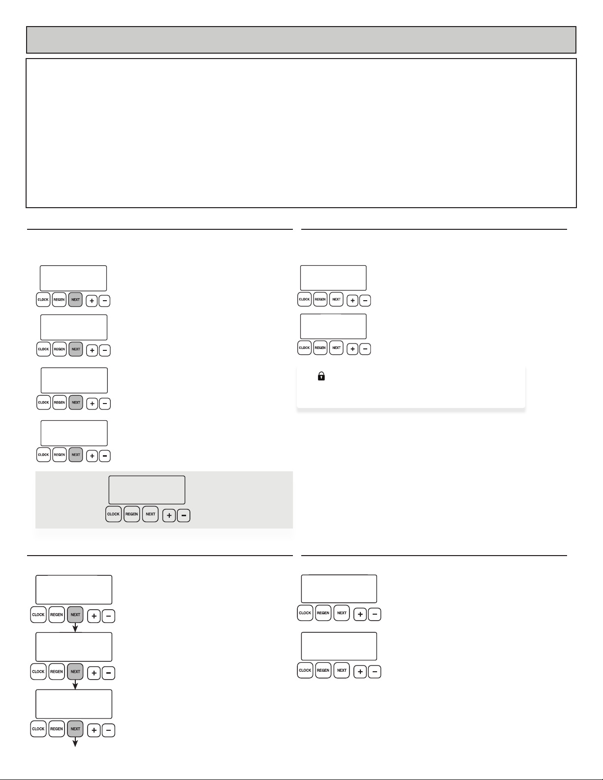
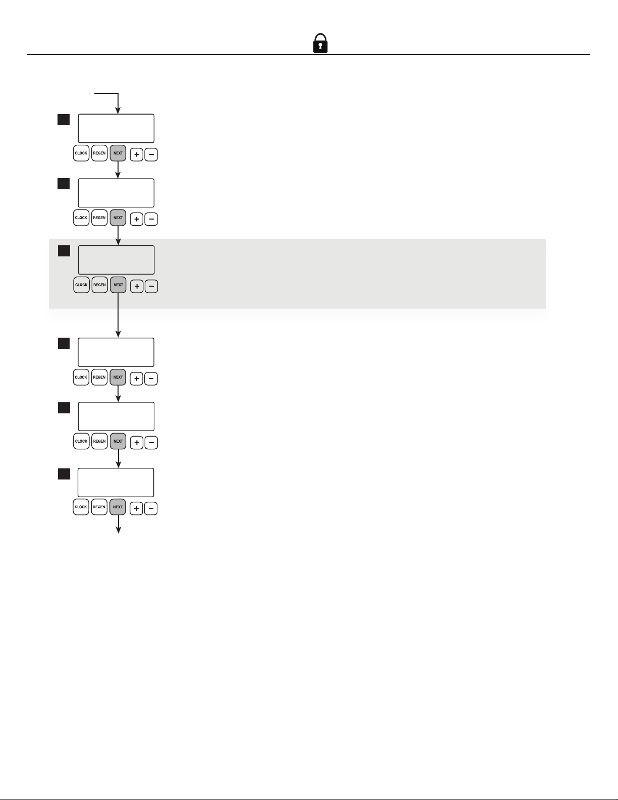
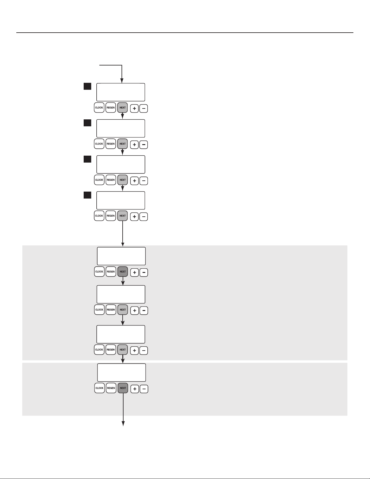
General Operation Screens
Press NEXT button to toggle between one of four displays.
Press REGEN button to schedule a regeneration for that night.
Return to general display
Displays current time
Unit defaults to this screen after a reset.
Displays a unit’s remaining capacity
This screen will not display if the unit’s gallons of
capacity is set to OFF. “REGEN TODAY” will alternate
with the current screen header if a regen is expected
that night.
Displays days remaining until a regen
This screen will not display if the unit’s day override
is set to o.
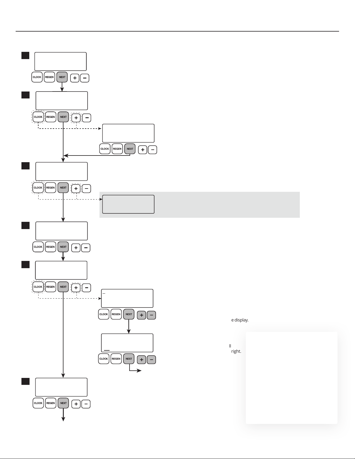
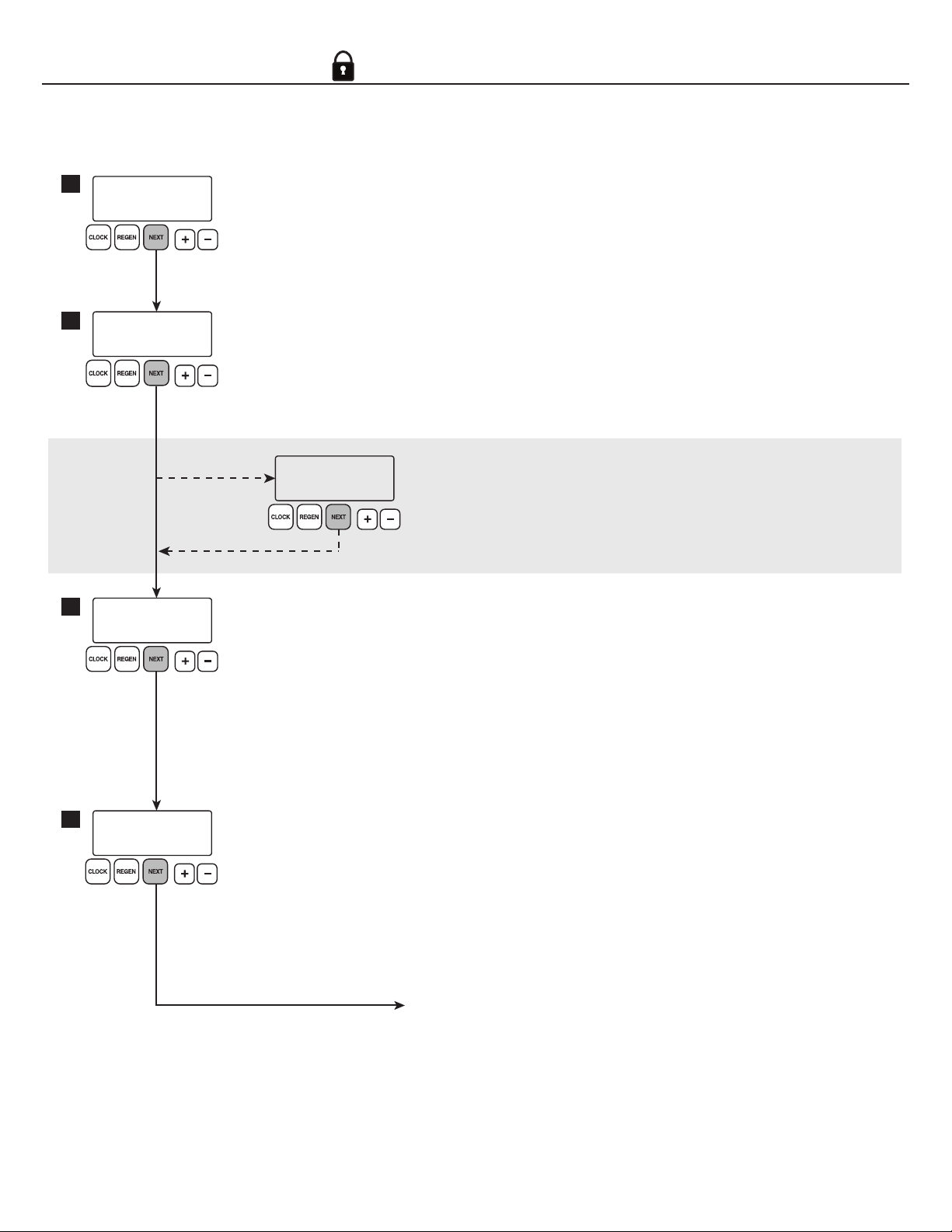
Set hours with + or — buttons
AM/PM toggles after 12 AM.
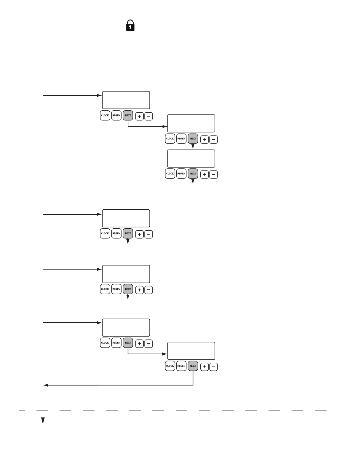
Displays time remaining in current regeneration cycle
“2” ashes for a second backwash if two backwashes are
programmed.
Displays time remaining incurrent cycle
If a chlorine generator is connected and set to ON, the
brine concentration will be checked during draw. Text will
alternate between DRAW TIME & GENERATOR ON.
Set minutes with + or — buttons
AM/PM toggles after 12 AM.
Set current day with + or — buttons
The default setting is WED.
Displays scrolling dealer
name and phone number
To change dealer name and
phone number, see page 3.
Displays current flow rate
“Current Flow Rate” is the amount of water currently
owing through, and being treated by, the unit. “GPM”
and the ow rate ash while the turbine is rotating.
555 5555555
DEALER NA
If set, a scrolling
dealer name and
phone number
screen will
alternate with the
selected general
operation screen.
CURRENT DAY
SET
WED
TIME MINUTES
SET
TIME HOUR
SET
2:00
2:35
AM
AM
MIN
BACKWASH REMAINING
2
3:30
GENERATOR ON
53:45
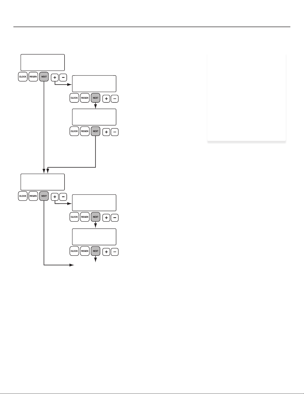
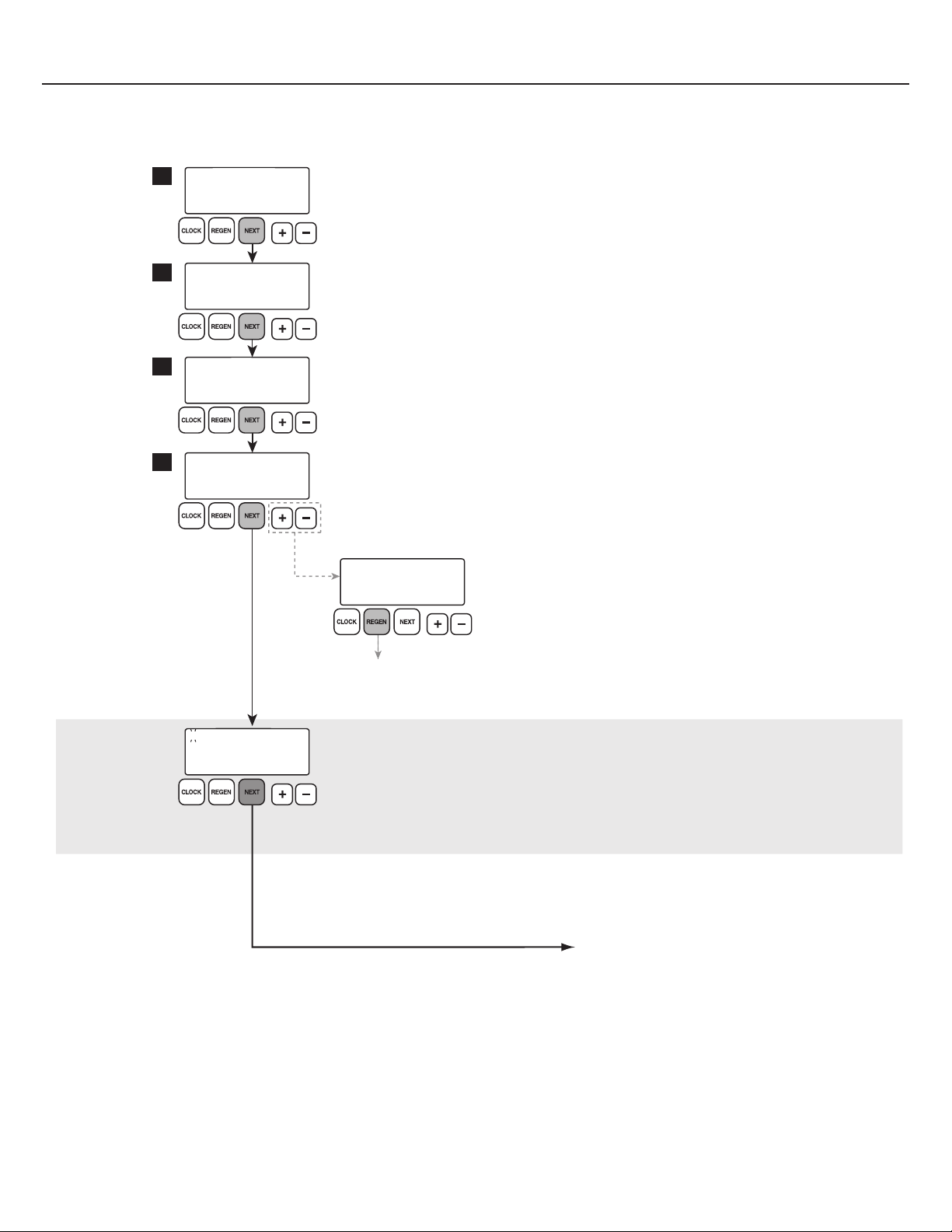
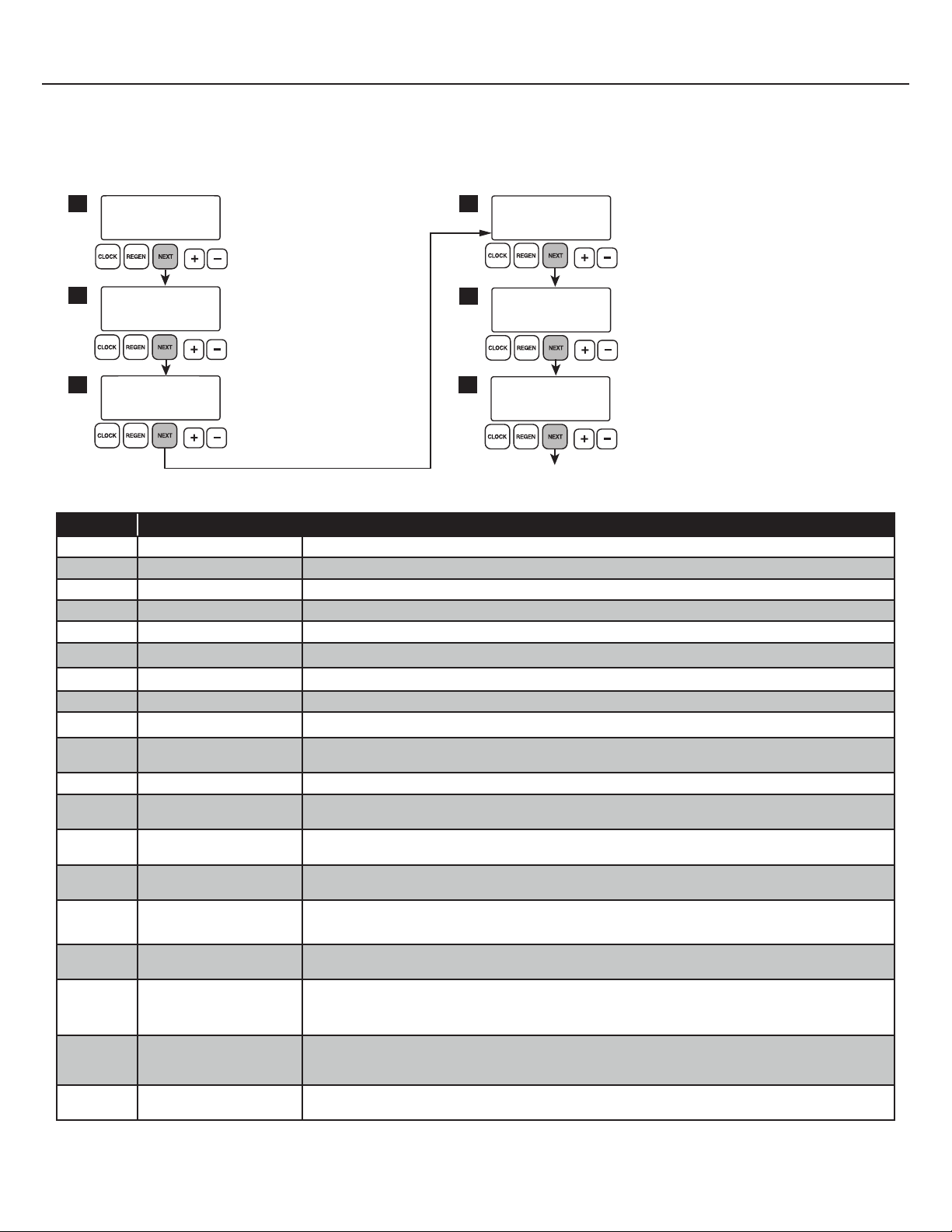
Unlock and Lock Controller
The following screens will flash when the correct button sequence is
inputted to unlock valve settings.
Indicates that the valve controller is unlocked
Unlocks access to advanced programming features
within the controller.
Indicates that the valve controller is locked
It is strongly advised to lock the controller following any
changes. This helps to prevent any accidental access to
advanced programming settings.
PROGRAM
UNLOCK
PROGRAM
LOCK
DAYS TO A REGEN
GPM
3
8
CAPACITY REMAINING
GPM GAL
1600
8
FLOW RATE
GPM
8.0
TIME OF DAY MON
GPM
2:408
PM
Set Time Screens Typical Regeneration Screens
Accessed by pressing the CLOCK button. Only visible when unit is in regeneration
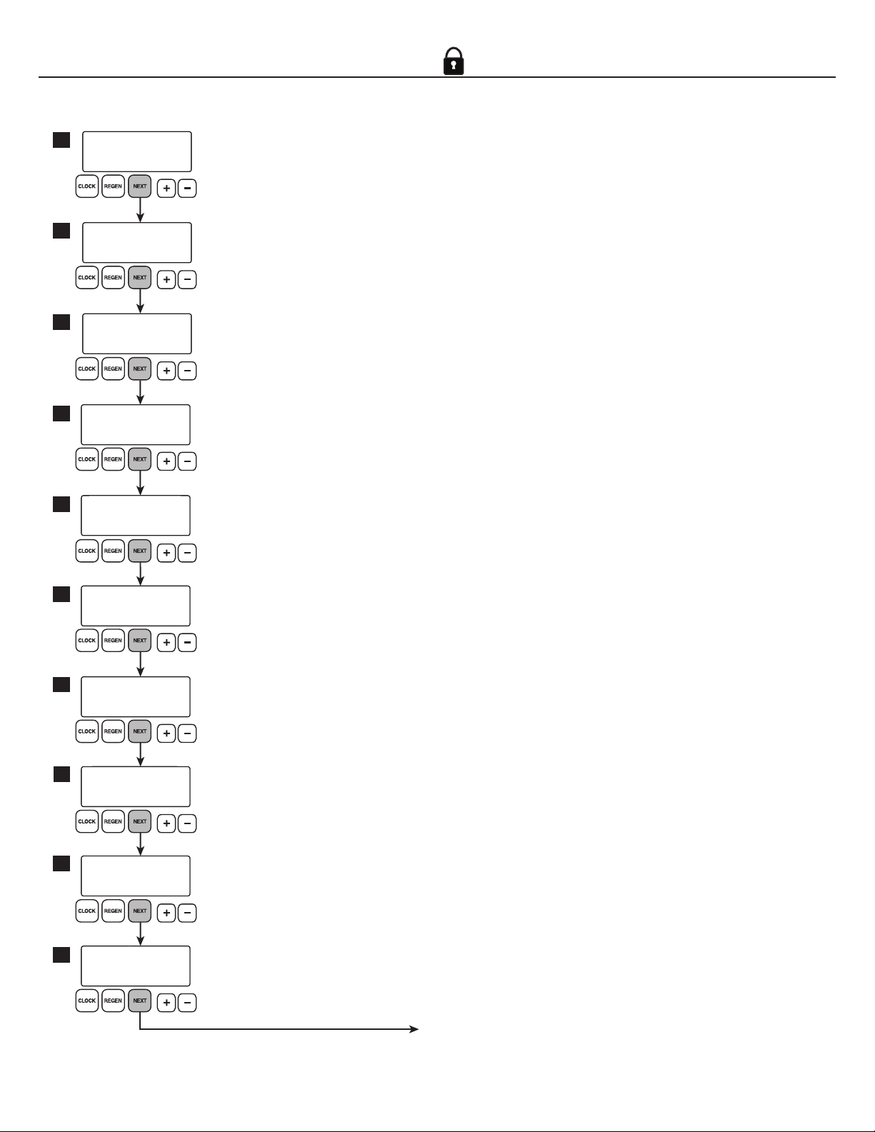
The symbol on the following pages indicates
that the screens below it will not display unless the
controller is unlocked.

3
REGEN TIME MINUTES
SET
2:00
AM
REGEN TIME HOUR
SET
2:00
AM
WATER HARDNESS
SET
20
GR
REGENS PER DAY
SET
4 PER
555-555-5555
555-555-5555
ALARM BUZZER
SET
ON
DEALER NA
1
3
DAYS BETWEEN REGEN
SET
6
2
4
5
LIGHT NORMALLY
SET
ON
6
SERVICE ALARM
SET
OFF
GAL
Installer/User Screens
Accessed by pressing and holding NEXT and +simultaneously for three seconds.
Returns to general display after five minutes of inactivity.
Set water hardness with + or — buttons
Adjustable from 1-150 grains, within limits determined by capacity settings as to not override gallons capacity setting.
Default setting is 20 grains.
NOTE: This screen will not display if the board is set to “FILTERING” mode (see OEM SOFTENING SECTION).
Set days between a regeneration with + or — buttons
Adjustable from 1-28 days, or OFF.
Default setting is 6.
Set days multiple number of regenerations per day
On the days between regen screen, press and hold the +and CLOCK
buttons simultaneously to access this screen.
Adjustable from 1-6 days. Selecting “OFF” returns to days between regen
screen. Choosing any other selection continues to regentimehour screen.
Set hour of regen time with + or — buttons
If IMMEDIATE REGEN is set (see Service OEM page), regen will be immediate
once total capacity is exhausted and ON ZERO will be displayed.
Default setting is 2:00 AM.
Activate Service Alarm
From the REGEN TIME HOUR screen, press and hold the +and CLOCK
buttons simultaneously to access this screen. See the service alarm section
on page 4 to congure alarms.
Set minutes of regen time with + or — buttons
If IMMEDIATE REGEN is set (see Service OEM page), regen will be
immediate once total capacity is exhausted and ON ZERO will be displayed.
Default setting is 2:00 AM.
Turn alarm buzzer ON or OFF with + or — buttons
When ON, an alarm will sound following a failed regeneration or when an error occurs.
Set backlight operation with + or — buttons
Default setting is ON.
OFF will turn display backlight o after 5 minutes of keypad
inactivity.
Scrolling contact name screen
Set contact name by using the +or –
buttons. Pressing the NEXT button will
advance the cursor one position to the right.
(55 Characters Max)
Access Scrolling Dealer Name and Phone Number Feature
From the alarm buzzer display, the dealer name and phone number feature can
be accessed by pressing the CLOCK and +buttons at the same time.
Set phone number by using the +or –buttons. Pressing the NEXT button will
advance the cursor one position to the right. Continuing to press the NEXT
button will advance to the contact name display.
Return to alarm buzzer screen
Return to general display
To Turn Off Dealer
Name/Number Screen
1. Clear the current phone number by pressing
the +or – buttons to toggle to the “blank”
character followed by the NEXT button.
2. Input two “blank” characters. The phone
number should clear and advance to the
dealer name setting.
3. Clear the current dealer name by pressing
the +or – buttons to toggle to the “blank”
character. Input blank characters to replace
any existing characters. Press the NEXT
button repeatedly until the Alarm Buzzer
screen appears.

4
Service Alarm Settings
Accessed by pressing and holding +and CLOCK buttons simultaneously for three seconds on the REGEN TIME HOUR screen.
Returns to general display after five minutes of inactivity.
SERVICE ALARM
SET
OFF
GAL
SERVICE ALARM
SET
OFF
YR
SERVICE ALARM
SET
10000
GAL
10000
GAL
CALL FOR SERVICE
IN
SERVICE ALARM
SET
1.00
YR
364
DAYS
CALL FOR SERVICE
IN
Turn service alarm by gallons ON or OFF with + or — buttons
Default setting is OFF.
Turn service alarm by years ON or OFF with + or — buttons
Default setting is OFF.
Use + or — buttons to set number of gallons
Adjustable from 100 - 9,999,000 gallons in 100
gallon increments.
Use + or — buttons to set number of gallons
Adjustable from .25 - 9.75 years in .25 year increments.
Status Display
Shows the gallons remaining before the service
alarm will trigger. Press and hold the +and –
buttons simultaneously for three seconds to
reset to the gallon setpoint.
Status Display
Shows the time remaining before the service alarm will trigger. Press the
+and –buttons for three seconds to reset to the year setpoint.
Continue to step 4 on page 3
The service alarm feature is used to warn
the owner that the unit currently needs
service. Some application examples includes
reminding the owner when a lter needs
replacement, when an R.O. system needs
servicing, or when routine maintenance
needs to be performed. This can be set by
gallons, time, or both. Default is OFF for both.
NOTE:
•When using service alarms, the top line will
read "Call for Service" and will alternate
with contact screen when in alarm mode.
•To reset a service alarm while in
status display, press + and – buttons
simultaneously for three seconds. This
will reset both gallon and year alarms
independently.

5
continue to next page
FILL
SET
CYCLE 1
DOUBLE REGEN
SET
10
%
>
GALLONS CAPACITY
SET
AUTO
SOFTENING
SET
CYCLE 2
CYCLE 3
SOFTENING TIME
SET
240:00
MIN
LBS
12:00
MIN
BACKWASH
SET
BACKWASH TIME
SET
FILL
SET
15.0
X1K
GRAINS OF CAPACITY
SET
32.0
SOFTENING
SET
TYPE
1
2
3
4
5
6
7
8
9
10
Service/OEM SOFTENING Screens
Accessed by pressing and holding NEXT and –simultaneously for three seconds.
Returns to general display after five minutes of inactivity.
Select SOFTENING or FILTERING with + or — buttons
If you have selected FILTERING, please refer to “Service/OEM FILTERING screens”, page 7-8.
Set system’s grains of capacity with + or — buttons
X1K = 1,000 grains.
The default setting is 32.0
Set gallon capacity with + or — buttons
•AUTO automatically calculates gallon capacity.
•OFF will regen by days override setting only.
•GALS BETWEEN REGEN will regen by specic gallon setting.
•The default setting is AUTO.
Set double regen point with + or — buttons
If unit’s capacity is overrun by this percentage, the unit will
regenerate two nights in a row. Default setting is 10%.
Set softening time with + or — buttons
This time window allows the salt to dissolve and achieve proper brine
strength. This process will start prior to regen time setting.
Default setting is 240:00 minutes.
Set salt pounds per regen with + or — buttons
The unit will deliver soft water during this position.
Default setting is 15.0 pounds.
Set backwash time with + or — buttons
Default setting is 12:00 minutes.
Set second cycle position with + or — buttons
This position is used between brine tank ll and the
start of backwash. The unit will deliver soft water
during this position.
Set third cycle position with + or — buttons
Set first cycle position with + or — buttons

6
Service/OEM SOFTENING Screens
Accessed by pressing and holding NEXT and –simultaneously for three seconds.
Returns to general display after five minutes of inactivity.
Set fourth cycle position with + or — buttons
Turn chlorine generator ON or OFF or change amount of chlorine to be generated by pressing and holding
the CLOCK and + buttons simultaneously. Press the + and – buttons to change to LOW, HIGH, or OFF.
Default setting is MEDIUM.
HIGH setting is used when additional chlorine production is necessary, such as in larger units.
Consult manufacturer before changing.
WARNING: If resin media is used, this setting MUST be set to OFF or LOW.
Set draw time with + or — buttons
Default setting is 90:00 minutes.
Set fifth cycle position with + or — buttons
Set final rapid rinse time with + or — buttons
Default setting is 4:00 minutes
Set end cycle with + or — buttons
Up to fourteen cycle positions may be programmed into a regeneration.
An END position triggers the end of a regeneration and a return to service.
CYCLE 4
REGENERANT DRAW DN
SET
90:00
MIN
DRAW TIME
SET
CYCLE 5
RINSE
SET
4:00
MIN
RINSE TIME
SET
CYCLE 6
END
SET
11
12
14
MEDIUM
GENERATE CHLORINE
13
15
16
continued from
previous page
return to general display

7
MAV DRIVE 1
SET
IN
DELAYED
SET
TYPE
OFF
VALVE TYPE
SET
1.0
AUXILIARY INPUT
SET
OFF
1
MIN
Pre-Service Rinse
SET
OFF
2
3
4
Configuration Screens
Accessed by pressing and holding NEXT and –simultaneously for three seconds.
Once screen changes, press and hold NEXT and –simultaneously again for three seconds.
Select meter size with + or — buttons
Set to 1”, 1.25”, 1.5”, 2” or 1.0T (for twin units). Upow brining will not be an option if set to anything other than 1” or 1.0T.
With 1.0T set:
•Meter calibration will be xed with a dierent value for each tank.
•MAV 1 setting will not be viewed, but forced to be set to Alternator Mode w/ Immediate Regen and Post Fill Brining.
•The Backwash-Air regeneration step will not be available.
•Default setting is 1”
Set auxilliary input with + or — buttons
•IMMED indicates unit will regen immediately.
•DELAY indicates that after a 2 minute signal from external contact, unit will regen at delayed regen time.
•HOLD indicates that unit will not regen while external contacts are closed.
•ALARM indicates that control valve’s internal alarm will sound upon external contact closure.
•Default setting is OFF.
WARNING: External contact is needed to operate any of the above settings properly. If no external
contact is connected, no setting is needed.
Set regen time control with + or — buttons
•DELAYED sets regen to specied regen time.
•DELAY + IMMEDIATE sets regen to occur after 10 minutes of no water usage.
•IMMEDIATE sets an immediate regen upon zero gallons of remaining capacity.
•Default setting is DELAYED.
Set pre-service rinse time with + or — buttons
This option is only available if the valve type is set to 1.0T (twin).
Range is 0-20 minutes. Default setting is OFF.
Set first MAV drive control with + or — buttons
•ALT A and ALT B are only used in twin congurations (see MAV manual for more details).
•SYSTEM CONTROLLER congures board to operate with the Clack System Controller.
•SEPARATE SOURCE changes state at the start and end of regen cycle.
•NO HARD BYPASS congures MAV as a no hard water bypass.
•TIME changes state at a set time referenced to the start of regen, for a preset duration of time independent
of actual regen status. Inactive during alternate regeneration cycle.
•Default setting is OFF.
•Screen not visible when unit is set to 1.0T
WARNING: Leaving valve in ALT A, ALT B or ENABLED without proper hardware will result in errors.
Only appears
on units set to
1.0T Mode
continue to next page

8
cont’d
RELAY 1 TRIGGER
SET
OFF
RELAY 1 TRIGGER
SET
TIME
RELAY 1 SETPOINT
SET
15
MIN
RELAY 1 DURATION
SET
90:00
MIN
RELAY 1 TRIGGER
SET
GALLONS
RELAY 1 SETPOINT
SET
25
GAL
RELAY 1 DURATION
SET
0:30
MIN
5
Configuration Screens
Accessed by pressing and holding NEXT and –simultaneously for three seconds.
Once screen changes, press and hold NEXT and –simultaneously again for three seconds.
Set first relay trigger with + button. Press + to reach desired triggering event.
If not using a relay, make sure OFF is selected and press NEXT.
OFF indicates that no external devices are being used.
Default is OFF.
return to
general display
return to
general display
return to
general
display
Set relay trigger with + or — buttons
TIME indicates that relay will be energized for a specied period
of time during regen only. To set by this, press NEXT.
Set relay setpoint with + or — buttons
This is the delay time period after regen starts that relay
will initially energize. 0 indicates an immediate start.
Set relay setpoint with + or — buttons
This is the gallons that will be expended before relay will
initially energize.
Set relay trigger with + or — buttons
GALLONS indicates that relay will be energized after a specied number of
gallons are expended in service position only. To set by this, press NEXT.
Set relay duration with + or — buttons
This is the duration of time, after relay setpoint, that relay
will remain energized.
NOTE: Can be all or any part of total regen time, but will
turn o at end of regen.
Set relay duration with + or — buttons
This is the duration of time, after relay setpoint,
that relay will remain energized. Adjustable from
1 sec to 500 min.
NOTE: Will shut o if a regen is initiated
continued from
previous page
continue to next page
If using Relay:
1. Press + to engage
one of the following
Relay Triggers:
• Time
• Gallons
• Regen
• Error
• Flow
• Pulse
2. Press NEXT to
program Setpoints
and Durations

9
cont’d
0:30
MIN
RELAY 1 TRIGGER
SET
REGEN
RELAY 1 TRIGGER
SET
ERROR
RELAY 1 SETPOINT
SET
25
GAL
RELAY 1 DURATION
SET
RELAY 1 SETPOINT
SET
1.00
PPG
RELAY 1 TRIGGER
SET
PULSE
RELAY 1 TRIGGER
SET
FLOW
Configuration Screens
Accessed by pressing and holding NEXT and –simultaneously for three seconds.
Once screen changes, press and hold NEXT and –simultaneously again for three seconds.
Set relay trigger with + or — buttons
REGEN GALLONS indicates that relay will be energized after a specied number of gal-
lons are expended during service and regen. To set by this, press NEXT.
Set relay trigger with + or — buttons
ERROR indicates that relay will be energized while unit is in an error mode. To set by
this, press NEXT.
Set relay trigger with + or — buttons
FLOW indicates that relay will close whenever ow is detected by the control. To set by
this, press NEXT.
Set relay trigger with + or — buttons
PULSE indicates that relay will generate a dry-contact signal output. To set by this,
press NEXT.
Set relay setpoint with + or — buttons
This is the gallons that will be expended before relay will
initially energize.
Set relay setpoint with + or — buttons
Set meter pulses per gallon (PPG). Adjustable
from 0.10, 0.25, 0.50, 0.75, and 1.00 – 10.00 in 1
PPG increments.
Set relay duration with + or — buttons
This is the duration of time, after relay setpoint, that relay
will remain energized. Adjustable from 1 sec to 500 min.
return to
general display
return to
general display
return to
general display
continued from
previous page
return to
general display

10
First Level History Screens
Accessed by pressing and holding +and –simultaneously for three seconds.
Returns to general display after five minutes of inactivity.
DAYS SINCE REGEN
5
VOLUME SINCE REGEN
980
RESERVE FOR
MON GAL
GAL
320
GAL
230
USAGE WED R
DAY
15
A→BGAL
0.00
1 3 DAYS 12:35
1
2
3
4
GAL
0
WED 12– 1 AM
DAY
15
Displays number of days since last regen
Displays number of gallons since last regen
Displays reserve capacity
Use +or – buttons to scroll through each day of the week to view calculated reserve capacity.
This screen will not appear when Immediate Regeneration is set (See page 7)
NOTE: Reserve capacity takes 21 days to generate.
Displays gallon usage by hour any time within last 90 days
Access by pressing +and – buttons simultaneously for three seconds.
Use the +and –buttons to scroll through each hour of the day selected in the
gallon usage history screen. To select a dierent day, press the REGEN button to
return to the previous screen and select a new day with the +or –buttons.
NOTE: Reserve capacity takes 21 days to generate.
Only appears
on units set to
1.0T Mode
Displays tank transfer history
Use +or – buttons to scroll through last 10 tank transfers. Viewed in 1.0T Mode only.
•“1” indicates most recent tank transfer.
•“A” indicates service ow transferring away from tank.
•“B” indicates service ow transferring to tank.
•“3” indicates days ago of transfer (99 day max)
•“0.00” indicates gallons used at time of transfer.
Displays gallon usage history
Use +or –buttons to scroll through past 90 days of water usage history.
1.0T Mode: T1 and T2 usage for this day combined in this display
•“R” indicates a regen has occurred that day. •“S” indicates a step through manual regeneration.
•“M” indicates a manual regeneration. •“E” indicates a valve error has occurred.
return to previous screen
continue to next page

11
cont’d
TOTAL REGENS
190
TOTAL DAYS
970
MON GPM
12
MAX FLOW HISTORY
TOTAL GALLONS
X1K
0
VVVCYC
TTT
MAV 1 - FIRST
CCC
%BRINE
REGEN
15 100
5
6
7
8
BRINE DRAW TIME 1
4.6 2:17
TOTAL BRINE ERRORS
1
VLT MIN
First Level History Screens
Accessed by pressing and holding +and –simultaneously for three seconds.
Returns to general display after five minutes of inactivity.
Displays peak flow rate history
Use +or – buttons to scroll through last 7 days to view peak
ow rate for that day.
Displays brine concentration history
Use +or –buttons to scroll through last 50 regenerations to view brine
concentration. Units with multiple brine cycles only record the rst one.
Displays voltage consumed and brine draw time
Use +or –buttons to scroll through last 50 regenerations to view voltage
consumed along with the time it took to draw brine from tank.
Displays voltage consumed and brine draw time
Errors will be recorded from all brine cycles.
Displays MAV drive time history for an active MAV 1 output
Use +or –buttons to select a MAV output. Pressing both +and –buttons
will reset this display.
•First = Average of the rst three drive times measured for that MAV in that direction.
•Last = Last drive time measured for that MAV in that direction.
•Ave = Current average drive time calculated for that MAV in that direction.
•TTT = Relative MAV drive time measured (First/Last/Ave).
•CCC = Total number of cycles in/out for that MAV.
•VVV = Relative MAV drive voltage measured (First/Last/Ave).
Displays total days unit has been in service
Displays total regens since startup
Displays total gallons used by Meter 1
input since last reset
Press and hold +and –buttons simultaneously for
three seconds to reset this value back to 0 gallons.
Only appears on units
equipped with chlorine
generator option
Only appears on
units equipped
with MAV.
return to
general display
continued from
previous page

12
SOFTWARE VERSION
XXXxx
TOTAL GALLONS
0
X1K
TOTAL DAYS
970
TOTAL REGENS
190
1
ERROR LOG 6146
101
1 4
6
TOTAL BRINE ERRORS
1
5
2
3
Second Level History Screens
Accessed by pressing +and –simultaneously for three seconds.
Once screen changes, press +and –simultaneously again for three seconds.
Non-resettable history.
Displays software version
Displays total gallons used by
Meter 1 since startup
Displays total days unit has been
in service
Displays total regens since startup
Displays last ten valve errors that occurred
Scroll through with +or –buttons.
A four digit number in the upper right corner of the
display indicates the motor position during the time
of error for logged drive errors.
Displays last ten valve errors that occurred
Scroll through with +or –buttons.
Error Code Error Code Description
101 UNABLE TO START: Valve not sensing valve movement with motor energized.
102 MOTOR STALLED: Valve unable to nd next cycle position (stalled).
103 MOTOR RAN TOO LONG: Valve unable to nd next cycle position.
104 VALVE HOMING: Valve unable to nd Home position.
106 MAV 1 RAN TOO LONG: MAV 1 motor ran too long. Unable to nd proper park position.
107 MAV 1 STALLED: MAV 1 motor ran too short. Unable to nd proper park position (stalled).
109 INVALID MOTOR STATE: Control can no longer operate properly due to detection of an invalid motor state.
116 MAV 2 RAN TOO LONG: MAV 2 motor ran too long. Unable to nd proper park position.
117 MAV 2 STALLED: MAV 2 motor ran too short (stalled). Unable to nd proper park position.
201 INVALID REGEN STEP: Control can no longer operate properly due to detection of an invalid
regeneration cycle step. Internal software issue.
204 LEAK DETECTED
402 POWER DOWN MEMORY: Check sum error for operational data and status section of EEPROM memory
- specic type of memory error.
403 PROGRAM MEMORY: Check sum error for programming section of EEPROM memory
- specic type of memory error.
404 DIAGNOSTIC MEMORY: Check sum error for diagnostic section of EEPROM memory
- specic type of memory error.
405 HISTORY MEMORY: Check sum error for history section of EEPROM memory
- specic type of memory error.
406 CONTACT MEMORY: Check sum error for contact screen section of EEPROM memory
- specic type of memory error.
407 STATUS RAM MEMORY
FAILURE:
Control can no longer operate properly due to corrupted data detected in the Operational Data and Status Section
of RAM memory. Once generated, the Error Mode is not entered nor an error displayed, instead previously stored
data (<6 hours old) is used to maintain control operation.
408 DIAGNOSTIC RAM
MEMORY FAILURE:
Control can no longer operate properly due to corrupted data detected in the Operational Data and Status Section
of RAM memory. Once generated, the Error Mode is not entered nor an error displayed, instead previously stored
data (<6 hours old) is used to maintain control operation.
410 CONFIG DOWNLOAD: Conguration le downloaded to the control was not originally uploaded from
another control with the identical software revision.
Error Codes and Descriptions
REMINDER: Press and hold NEXT and REGEN for three seconds to perform a soft reset and clear an error on screen.
return to
general display

13
Notes

14
Notes

15
Notes

1900 Prospect Court • Appleton, WI 54914
Phone: 920-739-9401 • Fax: 920-739-9406
MAN-SAN PL MAST Rev A0219
Table of contents
Other Water Right Water System manuals
Popular Water System manuals by other brands

ICA
ICA AQUA OCEAN AQ4000 instruction manual

Condair
Condair RO Series Installation and operation manual

3P Technik
3P Technik Rustico instruction sheet

Halsey Taylor
Halsey Taylor GreenSpec HTHB-HVRGRN Installation, care & use manual

August
August AT-6 manual

Riello
Riello 7200 Kombi Plus Installation, operation and maintenance manual

TMC Aquarium
TMC Aquarium V2React 300 Compact Instructions for installation and use

North Star
North Star NSRO42C4 Installation and operation manual

Elkay
Elkay ERS1-2F Installation, care & use manual

ZURN
ZURN Z1325 Assembly manual

PAW
PAW HeatBloC K32 DN 25 Installation & operation instructions

Grunbeck
Grunbeck GENO-mat F 500 A Operation manual