Water Soft ISOBAR III User manual
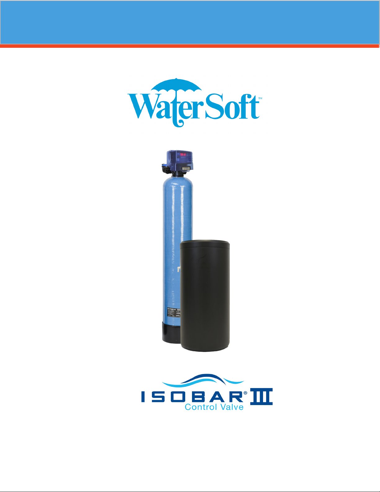
Softener Manual
Installation / Operation Manual

2
www.watersoftinc.com
Online at
Register Your Product
Softener Specications............................................................ Page 3
Softener Installation................................................................. Page 5
Programming the Control Valve............................................... Page 10
Control Start-Up Procedures................................................... Page 12
Master Programming............................................................... Page 13
Utilizing Bluetooth................................................................... Page 14
Control Valve Powerhead Assy. ISO III................................... Page 18
Valve Body Assembly ISO III................................................... Page 19
Bypass Assembly ISO III.......................................................... Page 21
Service Instructions................................................................. Page 22
Troubleshooting........................................................................ Page 24
Error Codes.............................................................................. Page 26
Warranty Information............................................................... Page 28
FCC Compliance Statement:
http://www.chandlersystemsinc.com/files/FCC_Compliance_Statement.pdf
Industry Canada Compliance Statement:
http://www.chandlersystemsinc.com/files/Industry_Canada_Compliance_Statement.pdf
One or more features of this product are covered by U.S. patents, visit http://www.watersoftinc.com/patents.php
for more information.
3
WARNING
Lubricants
Do NOT use Vaseline, oils, hydrocarbon lubricants or spray silicone anywhere! Petroleum base lubricants
will cause swelling of o-rings and seals. The use of other lubricants may attack plastic Noryl®. It is recom-
mended that Dow Corning® silicone grease be used as a lubricant for all control valves. Dow Corning® 7
Release Compound is used in the manufacture of Chandler Systems control valves. (Part # LT-150)
Sealants
Pipe dope and liquid thread sealers may contain a carrier that attacks some plastic materials. It is recom-
mended that Teon® tape be used to seal plastic Noryl® threaded ttings.
Softener Specications
General Specications DS24-3
DS24V-3
DS32-3
DS32V-3
DS48-3
DS48V-3
DS64-3
DS64V-3 DS96V-3
Grains Capacity - Regeneration / Lbs Salt Used* 20,000 / 7.5 27,000 / 9 40,000 / 15 54,000 / 18 81,000 / 27
Maximum Raw Water Hardness (grains) 50 75 100 100 100
Maximum Clear Iron / Manganese 3 5 55 5
Exchange Resin (cu ft per tank)
.75
1.0 1.5 2.0 3.0
Mineral Tank Size 8 x 44 9 x 48 10 x 54 12 x 52 13 x 65
Brine Tank (polyethylene w grid & safety) 16 x33 16 x 33 16 x 33 18 x 40 18 x 40
Service Flow Rate** (gpm) 8.0 10.0 11.0 12.0 14.0
Backwash Flow Rate (gpm) 1.5 2.0 2.4 3.5
Backwash Flow Rate (gpm) Vortech (V) Units 1.21.5 2.0 2.4 3.0
Gallons Used / Regeneration Vortech (V) Units 69 78 90 117 126
Gallons Used / Regeneration 79 90 101140 126
Space Required (D x W x H) 16x26x 53 16x27x 56 16x28x62 18x30x60 18x32x74
Approximate Shipping Weight (lbs) 88 100 133 164 285

4
PLEASE NOTE THESE SPECIFICATIONS BEFORE PROCEEDING
OPERATING PRESSURE RANGE : 20 - 125 PSI
OPERATING TEMPERATURE RANGE : 33º F - 120º F
INLET / OUTLET PIPE SIZE : 3/4: FNPT
PLEASE COMPLY WITH ALL APPLICABLE PLUMBING CODES
PROTECT THE SOFTENER AND PIPING FROM FREEZING TEMPERATURES
Please read the entire Owner’s Manual and Instruction before installation.
This Owner’s Manual must stay with the unit.
-How A Water Softener Works-
Water hardness is derived from Calcium and Magnesium minerals that have been dissolved into the water
under the earth’s surface. These minerals are found in limestone deposits and are the source of hard water.
The amount of hardness in a given water supply is dependent upon the quantity of Calcium and Magne-
sium present and the length of time water has been in contact with them. This can vary dramatically from
well-to-well and, for this reason, a water analysis is imperative in order to determine the proper treatment
method. The degree of hardness increases as the concentration of Calcium and Magnesium “ions” increase
and is measured in Grains Per Gallon (gpg).
The problem of hard water in the home / business comes to light in many facets of daily use. Water spots
and scum left behind on bathtubs, xtures and showers; wear and tear on appliances; calcium build-up
in hot water heaters and piping; and, greater amounts of soap and detergents being used are just a few
examples.
The modern water softener is designed to reduce hardness ions and their unpleasant side eects. Special
resin beads in the softener mineral tank are used to change hard water into soft water. The surfaces of
these beads are covered with sodium ions. As hard water enters the mineral tank and comes into contact
with the resin, an exchange of ions takes place as dissolved Calcium and Magnesium ions cling to the resin
surface and sodium ions take their place, thus softening the water. This process is called Ion Exchange.
Over time, the sodium ions used for the exchange process become depleted and must be replenished.
The water softener provides a Regeneration process whereby brine solution enters the mineral tank, driv-
ing-o the collected hardness ions and replenishes the surface of the resin beads with more sodium ions.
This process is automatically initiated by the control valve on the mineral tank. The regeneration process
has ve basic cycles as follows:
1. Backwash - The control valve directs the water ow in a reverse direction through the mineral tank,
separating the resin beads and ushing any accumulated particles to a waste drain.
2. Brine & Rinse - In the rst part of this cycle, the control valve directs brine solution downward through
the mineral tank, driving-o collected hardness ions and replenishing the resin beads with sodium ions.
The second part of the cycle rinses hardness ions and excess brine from the mineral tank to the waste
drain.
3. Rapid Rinse - The control valve directs the water ow downward, settling and recompacting the resin
bed.
4. Brine Rell - The control valve directs fresh water into the salt compartment to create new brine solu
tion for the next scheduled regeneration.
5. Service - This is the normal “operating” cycle where hard water enters the mineral tank, comes into con
tact with the resin beads and exchanges hardness ions for sodium ions - the water then becomes “soft”
and ready for use.
Softener Specications

5
-Pre-Installation Check List-
A water test should always be performed in order to determine total water hardness (in gpg) and total
dissolved iron (in parts per million - ppm). This is critical for proper equipment selection, sizing and for
determining the program for regeneration frequency. If heavy concentrations of iron (above 5 ppm), iron
coloration, iron bacteria or sediment are present, ltration prior to the softener will most generally be re-
quired. Certain states may require a licensed plumber for installation.
Note: Flexible water supply connectors and exible drain line tubing may not be allowed in you locale.
Please check with local plumbing code ocials prior to installation.
Installation Requirements
• A level oor position ahead of piping into water heater.
• Unit must be installed at least 10’ ahead of the inlet to a water heater to prevent damage due to back-up
of hot water.
• DO NOT install the unit in an area of direct sunlight or where freezing temperatures may occur!
(See Installation Diagrams for proper placement and plumbing connections.)
-Major System Components-
1. Brine Tank - This tank holds the salt that is added to the softener. This salt is dissolved with water to form
a brine solution used in the softener regeneration process.
2. Resin Tank - This tank contains the ion exchange resin media. Water ows through the resin tank under
pressure to come into contact with the resin for water softening.
3. Control Valve - The valve directs water through the resin tank for water softening and controls the ow
of water / brine for the regeneration process.
Installation

6
Installation
-Softener Location / Other Requirements-
• Locate the unit near an unswitched, 120 volt / 60 Hz grounded electrical outlet.
• Check for distance and proper drain installation (e.g. oor drain, washing machine standpipe).
• Determine type and size of piping required for softener connection (e.g. copper, galvanized, PVC plastic).
Note
• If household plumbing is galvanized and you intend to make the installation with copper (or vise versa),
obtain di-electric unions to prevent dissimilar metal corrosion.
• Where the drain line is elevated above the control valve or exceeds 20 feet in length to reach the drain,
use 3/4" I.D. drain line tubing instead of 1/2" I.D. Drain line tubing is not included.
• All plumbing lines not requiring “soft” water should be connected “upstream” of the softener.
• The brine tank drain line is gravity ow and must discharge below the overow tting.
• The brine overow is provided as a back-up in the event the safety oat shut-o should fail, allowing the
brine tank to overll. This drain connection would then carry the excess water to the drain and prevent
ooding of the oor. Therefore, no liability will or can be assumed by the manufacturer of the softener
should this occur.
Caution
• If sweat soldering copper pipe (remember to always use lead free solder and ux), cover yoke and bypass
valve with wet rags to prevent heat damage to connections and control valve! If using PVC or plastic pipe
primers and solvent cements specically recommended for use with potable water are required.
• Do not “TEE” to the main drain line from control valve.
7
-Installation Procedure-
- Water Supply Connections and Bypass Valve -
To allow for softener servicing, swimming pool lling or lawn sprinkling, a manual bypass valve has been
installed at the factory. The bypass allows hard water to be manually routed around the softener.
1. Position softener at desired location for installation. (See Installation Diagrams.)
2. For DS96V Units ONLY - The resin material is shipped separately from the mineral tank. Remove the
valve by unscrewing from center hole. Use a cork or tape to place over top of distributor tube to prevent
material from entering tube while lling. Place funnel in hole. Pour several gallons of water in the tank.
No gravel is required. Pour in the resin material. Remove funnel and cork or tape from distributor tube.
Clean tank threads and ll the mineral tank completely with water. Replace the valve, being careful to posi-
tion the distributor tube into the distributor tube pilot hole.
Note: If rebedding an existing unit and the system utilizes a standard tube & basket style distributor, a “D”
gravel underbedding will be required.
3. Turn OFF main water supply and OPEN nearest faucet to relieve pressure.
4. Cut main line and install appropriate elbows and extensions.
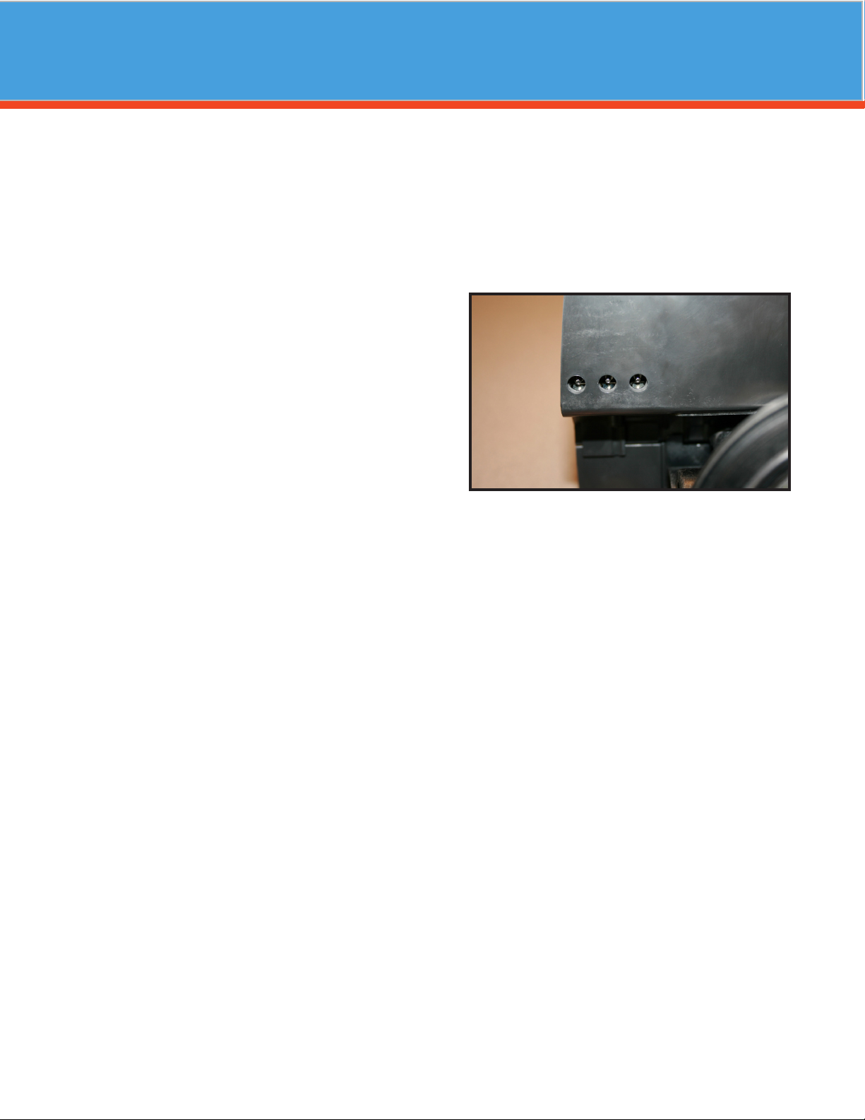
Caution: Raised arrows located on the sides of control valve body and bypass valve indicate proper direc
tion of water ow. Install inlet and outlet piping in direction of arrows. It is recommended that a
vacuum breaker be installed on the inlet plumbing.
5. Rotate bypass valve to the bypass position (position of lever is at right angle to inlet / outlet piping).
6. Turn the main supply line on to restore water service to the home.
7. OPEN nearest faucet to evacuate air and repressurize plumbing lines.
8. Check for leaks!
Installation
Bypass - Shown
8
Installation
- Drain Line Connection -
1. The drain line ow control assembly is pre-assembled for your convenience. Should you choose to hard
plumb the drain line, please remove the barb tting. The ow control housing can be removed by removing
the clip and pulling straight out on housing.
Note: When re-installing the drain line ow control housing, be sure you hear and feel the O-Ring pop into
place before inserting the clip.
2. Install 1/2” I.D. drain line tubing (not included) from hose barb to an open drain. A 4” gap between end of
the drain line and the open drain is required to prevent waste water backow. Keep the drain line as
short as possible. An overhead drain line can be used if necessary, but should discharge below the con
trol valve. A syphon trap (taped loop) at the outlet of the drain line is advisable to keep the drain line full
and assure correct ow during backwash. Elbows or other ttings must be kept at a bare minimum.
Note: Where the drain line is elevated above the control valve or exceeds 20 feet in length, 3/4” I.D. drain
line tubing should be used.
-Brine Line and Overow Connection-
Note: Your brine tank comes with two brine lines. Black is for outdoor installation. Opaque is for indoor installation.
Remove brass compression nut from the softener control
valve. Take brine tubing (packaged with brine tank) and
slide the brass nut and plastic ferrule onto one end of the
tubing. Find the plastic tubing insert (taped to the brine
well cap inside the brine tank) and insert it into the end of
the tubing. Next, insert the tubing into the control valve
and tighten the nut.
Inside the brine tank, remove the cap from the top of the
brine well. Feed the other end of the brine tubing through
the hole in the side of the brine tank, and rmly insert it
all the way into the push-lock elbow tting inside the brine
well. When this tubing is fully inserted, the tting will grab
the tubing and hold it in place.
BRINE LINE CONNECTION TO CONTROL VALVE BRINE LINE CONNECTION TO BRINE TANK
Insert
Nut
Ferrule
9
Battery Back-Up (Uses a standard 9-volt alkaline battery.)
Features of Battery Back-Up:
• During power failures, the battery will maintain the time of day as long as the battery has
power. The display is turned o to conserve battery power during this time. To conrm that
the battery is working, press either button and the display will turn on for ve (5) seconds.
• If power failure occurs while system is regenerating, the will motor to a shut o position to
prevent constant ow to drain. Depending upon system pressure and other factors, it is
possible to observe a reduced ow to drain during this step. After power is restored, the
unit will return and nish the cycle here it left o prior to the power interruption.
• When used without battery back-up, during a power failure, the unit stops at its current
point in the regeneration position and then restarts at that point when the power is re
stored. The time will be oset by the increment of time the unit was without power, so it is
necessary to reset the time of day on the unit. No other system will be aected.
- Pressurizing The System -
1. Make certain Control Valve is in SERVICE position.
2. Slowly rotate bypass valve to the SERVICE position. (Position of bypass lever is parallel to inlet / outlet
piping.)
3. Open the nearest faucet to evacuate air from plumbing lines.
4. Check for leaks! If water is observed leaking from bottom of bypass, close and open bypass lever several
times to seat o-rings. Exercise bypass valve
5. After air is evacuated from plumbing lines, close bypass (position of bypass lever is perpendicular to the
direction of inlet pipe) on bypass valve.
- Electrical Connection -
1. Connect the power cord and plug power supply into a 115 volt / 60 Hz receptacle.
Note : Do not plug into an outlet controlled by a wall switch or pull chain that could inadvertently be
turned o
Electronic Connections
P = Power Supply
B = Powered in Backwash Step Only (Cycle #1)
S = Powered for Entire Regen. Cycle
P B S
Installation

10
Main Menu
12:00
1. To enter Main Menu, press the Menu/Enter button.
(Time of Day will ash)
2. To set the Time of Day, press the Set/Change button.
(First digit will ash) Example [12-00]
- To change digit value, press the Set/Change button.
- To accept the digit value, press the Menu/Enter button.
- Next digit will ash to begin setting.
- Once the last digit display is accepted, all digits will ash.
3. To set A.M. or P. M ., press the Menu/Enter button.
- To change digit value, press the Set/Change button. Example [ A ]
- To accept the digit value, press the Menu/Enter button.
- Once A.M. or P.M. is accepted, the next menu item will ash.
4. b. To set Hardness an “H” will appear to enter Compensated Hardness in grains per gallon (gpg)
Default setting is 25 gpg. Example [ H - 25]
5. To Exit Main Menu, press the Menu/Enter button.
Note: If no buttons are pressed for 60 seconds, the Main Menu will be exited automatically.
Programming the Valve
11
Normal Operation
1. Home Display
The home display will alternate between the Time of Day and Gallons left until the next regeneration. The
meter will count down to zero (0000) and then regenerate at the scheduled time set.
Starting Extra Regeneration Cycle
1. To Start Delayed Extra Cycle Example [ 1]
- If Days Remaining Until Next Regeneration does not read ‘000’, press and hold the Set/
Change
button for 3 seconds until the display reads ‘0000’
- Regeneration cycle will initiate at the next designated regeneration time.
2. To start Immediate Extra Cycle First complete above step.
- With Gallons Remaining Until Next Regeneration at ‘0000’,
- Press and hold the Set/Change button.
- After 3 seconds, the regeneration cycle will begin.
3. To Fast Cycle thru regeneration First complete above 2 steps.
Note:Press and hold the Set/Change button for 3 seconds to advance to the next cycle step. Fast
Cycle is not necessary unless desired to manually step through each cycle step. (Repeat until
valve returns to the home display)
Note : Salt settings are pre-set at the factory for the maximum eciency.
Do not reduce salt settings below 9 lbs. per cu ft. as the water level in the brine tank will not reach
the grid plate.
Softeners Default (Min)
Step 1 Backwash 10
Step 2 Brine & Rinse 60
Step 3 Rapid Rinse 10
Step 4 Brine Rell 9 lbs/ cu ft
Programming the Valve

12
Control Start Up Procedure
- Start Up Procedure -
1. Advance control valve to BACKWASH (cycle 1) position and allow water to run to drain for 3 to 4 minutes.
Warning : Close valve on bypass prior to selecting the backwash position. After backwash position has
been established, slightly open bypass to evacuate air from the media tank. Fully open valve
when all air is depleted. This procedure will prevent media from being uplifted into control
valve.
2. Advance control valve to BRINE REFILL (cycle 4) position and allow the brine tank to ll just over the salt
grid plate.
3. Advance control valve to BRINE & RINSE (cycle 2) and allow the control valve to draw water from the
brine tank until it stops. If no draw is observed, check tightness of brine line compression ttings.
4. Advance control valve to RAPID RINSE (cycle 3) position and let run to drain for 3 - 4 minutes.
5. Advance control valve to BRINE TANK REFILL (cycle 4) position and allow the control valve to automatical
ly ll the brine tank.
Note: Control valve will advance to service position automatically.
- Disinfection -
For disinfection of your unit, please follow the Sani-System Procedure on the back of the packet provided.
- Filling The Brine Tank With Salt -
To expect a high level of performance and reliability, a salt manufactured specically for water softeners
must be used. Salt of this grade is virtually free from dirt and other particulates that would eventually
cause the softener to malfunction. A pellet type salt is recommended, although any high quality water soft-
ener salt (such as solar salt) will suce. If iron is present in raw water, use of iron inhibiting salt is recom-
mended. The salt level will decrease after each regeneration cycle. Consequently, the salt compartment will
need to be checked and replenished periodically.
1. Fill the brine tank or salt compartment with water softener salt as described above. This will be approxi
mately 250 pounds of salt. (150 lbs. for cabinet models.)
Warning: Do not ll salt above level of the brine well.
2. Replace brine tank lid.

13
Master Programming Mode
Master Programming Mode
To enter Master Programming Mode, press and hold both buttons for 5 seconds.
Note: All Master Programming functions have been preset at the factory. Unless a change is desired, it is
NOT necessary to enter Master Programming Mode.
1. Regeneration Time ( r ) Example [ r 2A ]
- The time of day at which regeneration may take place is designated by the letter “r”.
- Default regeneration time setting for SOFTENERS is 2a
- The rst display digit indicates A.M. or P.M. To change the value, press the Set/Change button.
- Press Menu/Enter button to accept the value and move to the next digit.
- The second and third display digits indicate the hour at which the regeneration will occur.
- Change the digits with the Set/Change button and accept with the Menu/Enter button.
- After the entire display ashes, press the Menu/Enter button to move to the next menu item.
2. Regeneration Day Override (A)
- Press Menu/Enter button. This display is used to set the maximum amount of time (in days) the
unit can be in service without regeneration. This setting is identied by the letter “A” in the left
digit. Regeneration will begin at the scheduled time. A setting of zero will cancel this feature.
- Example: Override every 7 days (A-07), default setting, or cancel setting (A-00). Maximum is 29.
3. Regeneration Cycle Step Times (Steps 1, 2, 3, 4) Example [ 3 - 10 ]
- The next 4 displays set the duration of time in minutes for each regeneration cycle step.
- The step number which is currently modiable is indicated on the far left of the display screen.
- The number of minutes allotted for the selected backwash step is displayed on the far right.
- Change the digit values using the Set/Change and Menu/Enter buttons as described above.
4. System Capacity in Grains ( c )
- Press the Menu/Enter button. This display is used to set the system capacity in grains and is used
in conjunction with the hardness setting to calculate total gallons of treated water available
between regenerations. This option is identied by the letter “c” in the left digit. The maximum
value for this item is 399.
Example: 32,000 grain capacity ( c 032 ).
5. Reserve Capacity Setting % Example (p - 25)
6. Bluetooth Enabled BE - 1 (ON)
BE - 0 (OFF)
7. Bluetooth Password BBPP is displayed for one second, then password is displayed.
8. To Exit the Master Programming Mode, press the Menu/Enter button until time of day returns.
Note: If no buttons are pressed for 60 seconds, the Master Programming Mode will be exited automatical
ly.

14
For simplied set up and control, please install the Legacy View on a compatible Bluetooth 4.0+ enabled
smart phone or tablet.
1. Download and install the Legacy View app from the Google Play Store, Apple App Store
2. Open the Legacy View app
• Choose a valve device at any time from the list of available devices to connect to by clicking on it.
• If the valve you want to connect to doesn’t show up, or there is a problem connecting to a device
you can press the “Scan for Devices” button or the Legacy View logo at any time to refresh the list
and start the process over.
• If the valve device is a BTLE valve and it has a password other than the default password, the rst
time you connect to it the app will ask you to enter the password. After entering it the rst time
you should not need to enter it again unless it changes.
3. BTLE Valve devices can be updated by the App. When the app is updated from the Google Play Store or
the Apple App Store, it may contain an updated rmware program for the valve devices. These updates
could contain new features or operational improvements. It is up to the user to allow these updates to be
sent to the valve device. Uploading a new program takes approximately 1 minute.
Dashboard
NOTE: Consult your dealer before making any changes
From the Dashboard, all items in ORANGE can be changed, while blue fields are informational only.
If you are unsure about the function of the eld click the for more information.
Utilizing Bluetooth Control

15
Set Up Utilizing Bluetooth App
Advanced Settings
NOTE: Consult your dealer before making any changes. We do not recommend changing Advanced
Settings unless you have a good understanding of the system operation.
From the Advanced Settings, all items in ORANGE with a “set” button can be changed.
For Filters:
Set Backwash Frequency
This sets the amount of day between backwash cycles
Change Time of Day (Press “SET” to set time automatically based on
device).
Set Regeneration Time
Example: For 2a.m., just type 2, choose a.m., and press ‘OK’
Note: If you have a lter and a softener the valves should be set to
regenerate at dierent times. Factory default times are 12a.m. for lters,
and 2 a.m. for softeners.
16
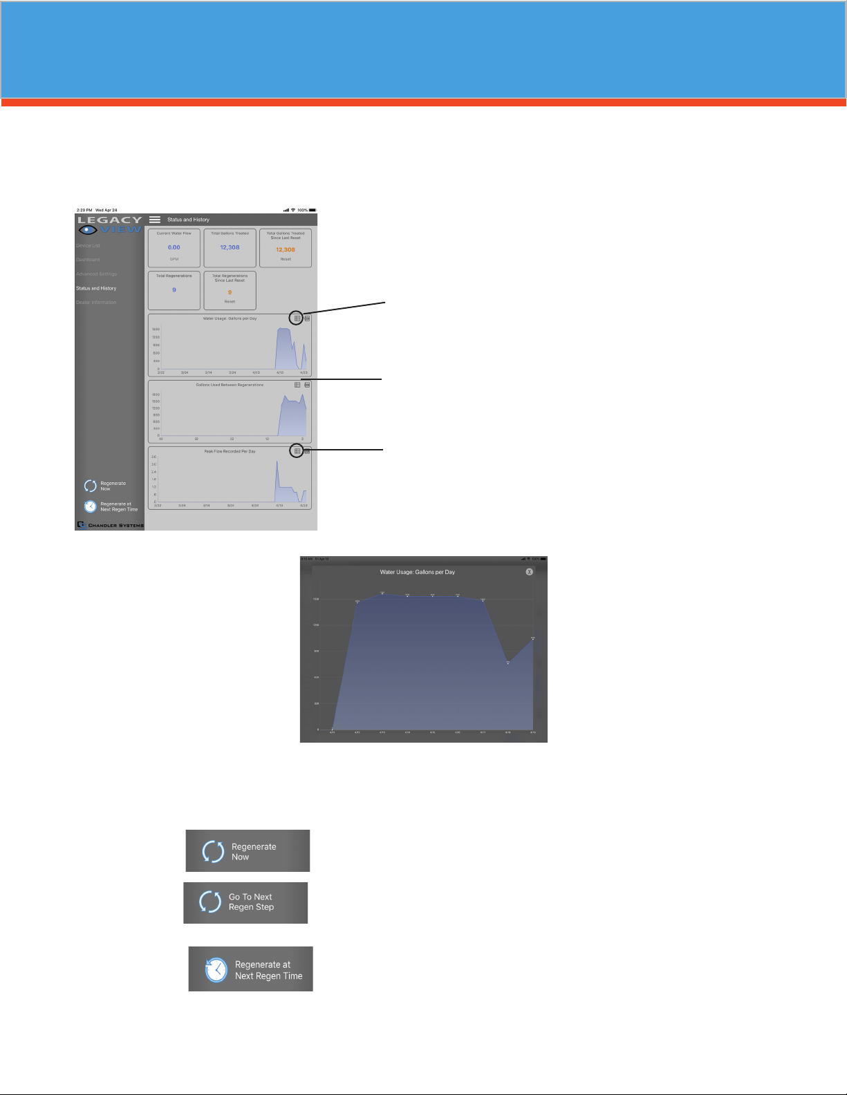
Status and History
From the Status and History, all items in ORANGE can be reset.
1. Start a regeneration or backwash cycle
Option 1: Click the “Regenerate Unit Now.”
Once a regeneration has been started, if you would like to force the
unit into the next cycle step click “Go to Next Regeneration Step”.
Option 2:
Touch any graph to enlarge and see
details. Enlarged graphs are able to
be zoomed in by pinching with two
ngers.
(Enlarged graph shown below)
“Regenerate Unit at Next Regen Time” button
This will take the system into a backwash cycle at the next regenera-
tion time.
Set Up Utilizing Bluetooth App
Pressing the .csv logo in the corner
will allow the graph data to be
exported and shared.
Enlarged graph showing water usage
Pressing this icon will show a list of
the data that is in the graph.

17
Master Programming Mode
- Final Check -
1. Be certain the bypass valve is in the SERVICE position.
2. Make sure the power supply is connected to an uninterrupted 115-volt outlet.
3. Check that the time of day is set
4. Double check regeneration schedule.
5. Make nal check for leaks!
6. Fill out warranty card online at www.csiwater.com
7. Leave all manuals with unit.
- Operation, Care and Cleaning -
When the bypass valve is in the SERVICE position (position of bypass lever is parallel to the inlet / outlet
piping), water is directed through the water softener. Water may be bypassed by turning the lever to the
bypass position (position of bypass lever is at right angles to inlet / outlet piping). Water to the home will
bypass the softener and be untreated.
You should manually bypass the softener if :
1. The outside lines do not bypass the water softener and water is to be used for lawn sprinkling or other
similar uses.
2. Servicing the water softener.
3. A water leak from the water softener is evident.
4. Shock treating water well and piping with chlorine or other disinfectant.
- To Skip A Regeneration -
1. For vacations or extended periods of absence, the power supply can be disconnected from the control
valve. It is recommended that the 9-volt battery be removed.
2. Upon return, plug in cord and reset the time of day. Replace 9-volt battery.
- General Care and Cleaning -
1. Do not place heavy or sharp objects on water softener or cabinet.
2. Use only mild soap and warm water to clean exterior of the unit. Never use harsh, abrasive cleaners.
3. Protect the water softener and drain line from freezing.
4. Reset time for daylight saving time periods.
5. Replace 9-volt battery once a year.
6. Inspect and clean the brine tank when sediment appears in the bottom of the salt compartment.
7. Always keep the brine tank supplied with good quality salt, a type designed for use in water softeners.

18
Control Valve Assembly
3
46
7
8
10
11
15
14
13
18
17
12
16
E
LETTERS IN DIAGRAM REPRESENT WIRING CONNECTIONS
1
E
P
M
PP
M
9
F
F
5
19
REF DESCRIPTION PART NO. QTY
0Metered Power Head Assy. 20943C100 1
1 Softener Circuit Boad Assy. 20943C102 1
2 Encoder 20001X124 1
3 Front Plate 20001X004 1
4 Encoder Wheel 20001X007 1
5 Main Gear 21001X120 1
6 Power Supply 20001X125 1
7 Back Plate 20001X005 1
8Lower Front Base For Cover 20111X002 1
9Legacy View Motor Assy. 20016X006 1
10 Lower Back Base for Cover 20111X003 1
11 Valve Cover 20111X017 1
12 6 X 1/2” Slotted, Hex Head 20001X003 1
13 6 X 1/2” Phillips, Pan Head SC10 3
14 6 X 1/2” Slotted, Hex Head Blk SC9 2
15 6 X 1/2 Fenderwasher SST 20001X002 1
16 Washer Circuit Board 20111X014 1
17 6-32 X 5/16” Phillips, Pan Head SC2 1
21 10-24 X 3/4” Screw SST 20001X001 2

19
Valve Body Assembly
2
9
1
3
13 14
12
16
17
18
19
10
11
45
6
8
15
20
7
6A

20
Valve Body Assembly
REF DESCRIPTION PART NO. QTY
1 Piston Assembly 20001X231 1
210-24 X 3/4” Screw SST 20001X001 3
3Seal and Spacer Kit 20561X253 1
4 End Spacer N/S 1
5
Flow Control Button 1.5
GPM
20251X266 1
Flow Control Button 2.0
GPM
20251X267 1
Flow Control Button 2.4
GPM
20251X268 1
6DLFC Assy. 20017X100 1
790 Degree Hose Barb Elbow 20017X266 1
8 Drain Retainer 20017X214 1
9 Brine Valve 20561X225 1
10 DLFC Assembly 20001X228 1
11 DLFC Ferrule 3/8” 20251X305 1
12 10-24 X 3/4” Screw SST 20001X001 2
13 Injector Cap 20001X223 1
14 Injector Cap Seal 20001X224 1
15 Injector, White 20017X219 1
Injector, Blue 20017X220 1
16 Injection Screen 20001X222 1
17 Plug 20001X217 1
18 Tank. O-Ring 20561X205 1
19 Dist. O-Ring 20561X204 1
20 Meter Assembly 20017X203 1
This manual suits for next models
9
Table of contents
Popular Water Dispenser manuals by other brands


Pentair
Pentair filter Owner's/operator's manual

US Water Systems
US Water Systems Escort 091-EPWS-1 owner's manual

WaterGroup
WaterGroup 185HEDP owner's manual

Mitte
Mitte Mitte home MHDE01 user manual

SpectraPure
SpectraPure Eliminator RO BASIC Series Installation and operating manual

Bunn
Bunn dispenser Installation and operating guide