Water Specialist WS2H User manual

Water Specialist WS2H and WS3
Control Valve Drawings and Service
Manual
HYDROCARBONS SUCH AS KEROSENE, BENZENE, GASOLINE, ETC., MAY
DAMAGE PRODUCTS THAT CONTAIN O-RINGS OR PLASTIC COMPONENTS.
EXPOSURE TO SUCH HYDROCARBONS MAY CAUSE THE PRODUCTS TO
LEAK. DO NOT USE THE PRODUCT(S) CONTAINED IN THIS DOCUMENT ON
WATER SUPPLIES THAT CONTAIN HYDROCARBONS SUCH AS KEROSENE,
BENZENE, GASOLINE, ETC.

Page 2 WS2H and WS3 Drawings and Service Manual

WS2H and WS3 Drawings and Service Manual Page 3
General Specifications and Pre-Installation Checklist ......................................................4
Software and Power Supply Compatibility .......................................................................5
Installation Instructions .....................................................................................................6
Installation Summary ........................................................................................................9
WS2H Control Valve Cycle Positions ............................................................................10
WS3 Control Valve Cycle Positions ...............................................................................13
Front Cover and Drive Assembly ...................................................................................16
WS2H Drive Cap Asy, Downflow Piston, Regenerant Piston, Spacer Stack Asy,
Drive Back Plate and Main Body, and Meter .................................................................17
WS3 Drive Cap Asy, Downflow Piston, Regenerant Piston, Spacer Stack Asy,
Drive Back Plate, Main Body .........................................................................................18
V3075 and V3075BSPT WS3 3” Meter Assembly..........................................................19
Brine Valve Body and Injector Components....................................................................20
Base Tank Adapters .........................................................................................................21
V3158-04 2” Drain Elbow ¾” Male NPT without silencer ............................................22
V3008-05 2” Drain Fitting 1” Straight Male NPT without silencer ...............................23
V3079 and V3080 NPT and BSPT 1” and 1.5” DLFC ...................................................24
V3051 and V3051 BSPT 2” DLFC ................................................................................25
V3764 and V3764BSPT 3” DLFC ASY.........................................................................26
V3063 and V3063BSPT 2” Motorized Alternating Valve ..............................................27
V3076 and V3076BSPT 2” Motorized Alternating Valve Rev2......................................28
V3098 and V3098BSPT 2” No Hard Water Bypass MxF ...............................................29
V3083 and V3083BSPT 3” Motorized Alternating Valve ..............................................30
V3099 and V3099BSPT 3” No Hard Water Bypass MxF ...............................................31
V3060 and V3060BSPT 2H Bypass Valve Auto and Manual .........................................32
V3053 WS2H 2.5” Groove Lock Clamp ........................................................................33
Error Codes .....................................................................................................................34
Trouble Shooting Guide ..................................................................................................35
Standard Injector Graphs ................................................................................................43
Table of Contents

Page 4 WS2H and WS3 Drawings and Service Manual
Table 1
General Specifications and Pre-Installation Checklist
Minimum/Maximum Operating Pressures 20 psi (138 kPa) -125 psi (862 kPa)
Minimum/Maximum Operating
Temperatures
40°F (4°C) – 110°F (43°C)
Power Adapter:
Supply Voltage
Supply Frequency
Output Voltage
Output Current
U.S.
120V AC
60 Hz
20V or 24V AC
800 mA
see Table 2
International
230V AC
50 Hz
20V or 24V AC
1000 mA
No user serviceable parts are on the PC board, the motor, or the Power adapter. The means of
disconnection from the main power supply is by unplugging the Power adapter from the wall.
Service flow rate WS2H Valve: 125 gpm (473 lpm, 28.4 m3/h) @ 15 psig (103 kPa) drop
WS3 Valve: 250 gpm (946 lpm, 56.8 m3/h) @ 15 psig (103 kPa) drop
Backwash flow rate WS2H Valve: 125 gpm (473 lpm, 28.4 m3/h) @ 25 psig (172 kPa) drop
WS3 Valve: 220 gpm (833 lpm, 50.0 m3/h) @ 25 psig (172 kPa) drop
CV Service WS2H Valve: 32.3
WS3 Valve: 64.6
CV Backwash WS2H Valve: 25.0
WS3 Valve: 44.0
Meter:
Accuracy
Flow Range
WS2H Valve: Internal Meter
+ 5 %
1.5 – 125 gpm (5.7 – 473 lpm)
WS3 Valve: Optional External
Meter
+ 5 %
3.5 – 350 gpm (13.3 – 1325
lpm)
Regenerant Refill Rate WS2H and WS3 Valves: Variable - Shipped from Factory with 2.2 gpm
(8.33 lpm)
Injectors WS2H & WS3 Valves: See Injector Graphs V3010-2A through 2H
Brine Line Adapters Included 1” Male NPT Elbow & ¾” x 1” Solvent Weld Elbow
Inlet, Outlet and Drain Line Openings WS2H Valve: 2” Female NPT or BSPT or 2.5” Groove Lock
WS3 Valve: 3” Female NPT or BSPT, No Groove Lock
Distributor Tube Opening:
WS2H Valve
WS3 Valve
Female NPT Inlet & Outlet
2.375” OD (2.0” NPS)
3.5” OD (3” NPS)
Female BSPT Inlet & Outlet
63 mm OD
90 mm OD
Tank Connection:
WS2H Valve
WS3 Valve
4”-8UN, 6” Flange, Side Mount (2” Female NPT or BSPT or 2.5” Groove Lock)
6” Flange or Side Mount (3” Female NPT or BSPT)
Shipping Weight WS2H Valve with Meter: 50 lbs (22.7 kg)
WS3 Valve: 57 lbs (25.9 kg) Meter Sold Separately
PC Board Memory Nonvolatile EEPROM
(electrically erasable programmable read only memory)
Compatible with the following typical
concentrations of regenerants/chemicals
Sodium chloride, potassium chloride, potassium permanganate, sodium bisulfite,
chlorine and chloramines

WS2H and WS3 Drawings and Service Manual Page 5
Software Version Power Supply
V3242-01BOARD
Main Board1
V3243-01BOARD
System Board
Output
Voltage Part # and Description
114.10 1.03
24 VAC
V34612WS2H/3 AC ADAPTER
V3461EU WS2H/3 AC ADAPTER EU
V3461UK WS2H/3 AC ADAPTER UK
114.11
115.17
1.07 or 1.08115.25
200.01
215.02
1.11 or 1.13215.03
215.04
215.10 1.11 or 1.13
24 VAC
V34612WS2H/3 AC ADAPTER
V3461EU WS2H/3 AC ADAPTER EU
V3461UK WS2H/3 AC ADAPTER UK
20 VAC3
V3461-01 WS2H/3 AC ADAPTER 20V
V3461EU-01 WS2H/3 AC ADAPTER EU 20V
V3461UK-01 WS2H/3 AC ADAPTER UK 20V
Table 2
Software and Power Supply Compatibility
1It is recommended to maintain one version throughout a system.
2Replacement V3461 power supplies have screw terminals and are shipped less a cord. Use cord from existing power supply to
connect to the screw terminals.
3V3461EU-01 and V3461UK-01 will not be available for sale until August 2010.

Page 6 WS2H and WS3 Drawings and Service Manual
BRINE/REFILL
DRAIN
INLET
OUTLET
INTERNAL
FLOW METER
BRINE/REFILL
OUTLET
DRAIN
INLET
Installation:
WS2H CONTROL VALVE TOP VIEW
WS3 CONTROL VALVE TOP VIEW

WS2H and WS3 Drawings and Service Manual Page 7
DISTRIBUTOR PIPE HEIGHT:
Recommended distributor pipe height for top mounted WS2H Control valves is 2 ¼” – 2 ½” above the top of tank for fiberglass
tanks. Please verify distributor pipe and pilot o-ring engagement and make proper allowances for tank expansion.
Recommended distributor pipe height for top mounted WS3 Control valves is 2 ½” – 2 ¾” above the top of tank for fiberglass tanks.
Please verify distributor pipe and pilot o-ring engagement and make proper allowances for tank expansion.
GENERAL INSTALLATION & SERVICE WARNINGS
The control valve and fittings are not designed to support the weight of the system or the plumbing.
Do not use Vaseline, oils, other hydrocarbon lubricants or spray silicone anywhere. A silicone lubricant may be used on black
o-rings but is not necessary.
HYDROCARBONS SUCH AS KEROSENE, BENZENE, GASOLINE, ETC., MAY DAMAGE PRODUCTS THAT
CONTAIN O-RINGS OR PLASTIC COMPONENTS. EXPOSURE TO SUCH HYDROCARBONS MAY CAUSE THE
PRODUCTS TO LEAK. DO NOT USE THE PRODUCT(S) CONTAINED IN THIS DOCUMENT ON WATER SUPPLIES
THAT CONTAIN HYDROCARBONS SUCH AS KEROSENE, BENZENE, GASOLINE, ETC.
THIS WATER METER SHOULD NOT BE USED AS THE PRIMARY MONITORING DEVICE FOR CRITICAL OR
HEALTH EFFECT APPLICATIONS
Do not use pipe dope or other sealants on threads. Teflon tape is recommended to be used on all threads.
Use of pipe dope may break down the plastics in the control valve.
When servicing the valve, water may leak from
the valve. Water from the valve may create a slip
hazard. Clean up water spills.
Disconnect from electrical power prior to
servicing the valve.
SITE REQUIREMENTS:
• The plug-in Power adapter is for dry locations only
• The tanks should be on a firm, level surface
• Electrical: Use an uninterrupted outlet installed within 15 feet (4.57 meters) of the water conditioner.
All plumbing should be done in accordance with local codes.
1. Locate the water conditioner so the distance between the drain and the water conditioner is as short as possible.
2. Regenerant tanks that must be refilled should be located where they are easily accessible. It is recommended a safety brine valve
be used.
3. Do not install any water conditioner with less than 10 feet of piping between its outlet and the inlet of a water heater.
4. Do not locate unit where it or its connections (including the drain and overflow lines) will ever be subjected to room temperatures
under 40° F (4° C).
5. The use of resin cleaners in a non-vented enclosure is not recommended.
Allow two feet of clearance to service WS2H and WS3 valves.
The valve will withstand transportation and storage temperatures of -13 ˚F (-25 ˚C) to 131 ˚F (55 ˚C) and for short periods up to 158
˚F (70 ˚C). If valve has been exposed to freezing conditions let valve warm up to room temperature before running water through it.
The valve has been packaged to prevent damage from the effects of normal humidity, vibration and shock.

Page 8 WS2H and WS3 Drawings and Service Manual
6. INLET/OUTLET PLUMBING: Connect to a supply line downstream of outdoor spigots. Install inlet and
outlet shutoff valves for the control valve; see top view drawings for control valve inlet and outlet locations.
Installation of a three valve bypass is recommended. If using plastic fittings ground the water conditioner
per local electric codes. If an external water meter is used, install the water meter on the outlet side of the
control valve. It is recommended that the meter assembly be installed horizontally or in a downflow vertical
position to reduce turbine bearing wear. The turbine assembly may be orientated in any direction. Remove
the cover and drive bracket and thread the water meter cord through the hole in the back plate. Reinstall the
drive bracket. Weave the cord through the strain relief on the backplate and connect the end to the three prong
connector labeled FLOW on the printed circuit board. Re-install the cover.
7. Drain: Verify that the drain can handle the backwash rate of the water conditioner. Correctly size the drain
line and install an appropriately sized drain line flow control. For WS2H and WS3 valves a drain line flow
control are NOT supplied with a valve. For WS2H valves the drain outlet is 2” Female NPT or BSPT threads
or 2.5” groove lock connection. For WS3 valves the drain port is 3” Female NPT or BSPT, no groove lock
connection. If using copper, solder joints near the drain must be done prior to connecting the drain line flow
control fitting. Leave at least 6” (152.4 mm) between the drain line flow control fitting and solder joints to
prevent heat from damaging the flow control. Avoid elevating the drain line above the control valve where
possible. Discharge the drain line through an air gap to a receptacle in accordance with local plumbing codes.
IMPORTANT: Never insert a drain line directly into a drain, sewer line, or trap. Always allow an air
gap between the drain line and the receptacle to prevent back siphonage.
8. Regeneration: If the control valve is to be used to regenerate the water conditioner with brine (saturated
salt solution) or other regenerants. The WS2H and WS3 control valves regenerant port has a 1” 90° Male NPT
threaded outlet connection that swivels 360°. To ensure acceptable operation of the injectors use 1” pipe to
connect to the brine tank. Smaller drain line flow controls may result in the injector performance not matching
the injector graphs. Use an adequately size drain line flow control to ensure proper brine draw.
See Table 3 for injector order number and size for tank diameter. An overflow drain line from the regenerant
tank that discharges into an acceptable drain is recommended, as a regenerant overflow could damage
furnishings or the building structure. Connect a line to the overflow fitting on the regenerant tank. If an
overflow fitting is not already installed on the regenerant tank, install one. Do not elevate the overflow drain
line. Discharge the overflow drain line through an air gap to a receptacle in accordance with local plumbing
codes.
Table 3
WS2H and WS3 Valve Injector Order Information
Injector Order Number Typical Tank Diameter4
V3010-2A 18”
V3010-2B 21”
V3010-2C 24”
V3010-2D 30”
V3010-2E 36”
V3010-2F 42”
V3010-2G 48”
V3010-2H 63”
All injector graphs are at the end of this manual for total, slow rinse and draw flow rates.
4Actual injector size used may vary depending on the design and application of the system. Injectors in table are sized for a typical
downflow softener using standard mesh synthetic cation exchange media regenerating with sodium chloride.

WS2H and WS3 Drawings and Service Manual Page 9
9. Power Adapter: If a Power Adapter is already connected to the control valve, plug the Power Adapter into
an uninterrupted outlet. If the Power Adapter cord has not yet been connected to the control valve, remove the
control valve cover and the drive bracket and thread Power Adapter cord through the hole in the back plate.
Reinstall the drive bracket. Weave the cord through the strain relief on the backplate and connect the end
to the four pin connector on the printed circuit board labeled POWER. Reinstall the cover. Plug the Power
Adapter into an uninterrupted outlet.
10. Program the control valve: It is very important to program the control valve for the type of system (e.g.
water softener of filter) and the end use application. Check the program used prior to testing the system.
Installation Summary
Installation Date:___________________________________________
Installation Location: _______________________________________
Installer(s): _______________________________________________
Phone Number: ____________________________________________
Application Type: (Softener)_______ Other: ____________________
Water Source: ____________________________________________
Water Test Results:
Hardness:___________ Iron: ___________pH:___________________
Other: ___________________________________________________
_________________________________________________________
Misc:
Service Flow Rates: min._________ max.___________
Tank Size: Diameter _________ Height: ______________
Resin or Media Volume: ___________________________
Resin or Media Type: _____________________________
Capacity: _______________________________________
Salt or Fill Setting per Regeneration: _________________
Brine Tank Size: _________________________________
Control Valve Configuration:
Valve Type: _____________________________________
Valve Part Number:_______________________________
Valve Serial Number: _____________________________
Regenerant Refill Control: _________________ gpm/lpm
Injector Size: ____________________________________
Drain Line Flow Control: __________________ gpm/lpm

Page 10 WS2H and WS3 Drawings and Service Manual
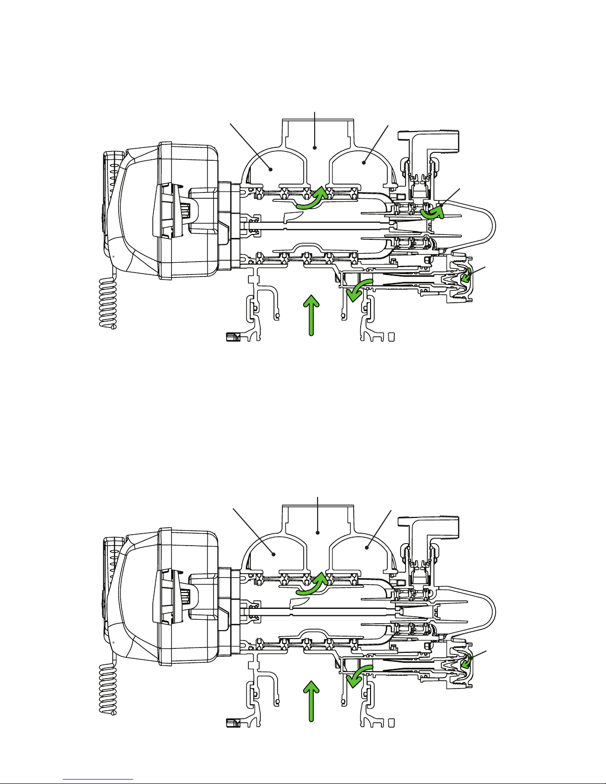
WS2H Control Valve Cycle Positions
SERVICE
BACKWASH
Treated Water Supply
Raw Water
Inlet
Raw/Hard Water is bypassed
during regeneration Backwash water
to drain
Raw Water
Inlet

WS2H and WS3 Drawings and Service Manual Page 11
DRAW
SLOW RINSE
Raw/Hard Water is bypassed
during regeneration Regenerant water
to drain
Raw Water
Inlet Regenerant
solution being
drawn in
Injector feed
water from Raw
Water Inlet
supply
Raw/Hard Water is bypassed
during regeneration Slow Rinse water
to drain
Raw Water
Inlet
Injector feed
water from
raw water inlet
supply

Page 12 WS2H and WS3 Drawings and Service Manual
RINSE
SOFT WATER REFILL
Rinse water
to drain
Raw Water
Inlet
Raw Water
Inlet
Raw/Hard Water is bypassed
during regeneration
Treated Water Supply
Refill port to refill
tube for treated water
Treated Water to
Regenerant Tank
Treated water
from Refill Tube

WS2H and WS3 Drawings and Service Manual Page 13
WS3 Control Valve Cycle Positions
SERVICE
BACKWASH
Treated Water Outlet
Raw Water
Inlet
Raw Water
Inlet
Raw/Hard Water is bypassed
during regeneration
Backwash Water
to Drain
Page 14 WS2H and WS3 Drawings and Service Manual
DRAW
SLOW RINSE
Raw Water
Inlet
Raw/Hard Water is bypassed
during regeneration
Backwash Water
to Drain
Regenerant
solution being
drawn in
Injector feed
water from Raw
Water Inlet
supply
Raw Water
Inlet
Raw/Hard Water is bypassed
during regeneration
Slow Rinse Water
to Drain
Injector feed
water from Raw
Water Inlet
supply

WS2H and WS3 Drawings and Service Manual Page 15
RINSE
SOFT WATER REFILL
Raw Water
Inlet
Raw/Hard Water is bypassed
during regeneration
Rinse Water to
Drain
Raw Water
Inlet
Treated Water Supply
Treated Water to
Regenerant Tank
Treated water
from Refill Tube
Refill port to refill
tube for treated water

Page 16 WS2H and WS3 Drawings and Service Manual
Front Cover and Drive Assembly
2
3
5
6
4
10
7
8
9
1
1a
Drawing No. Order No. Description Quantity
1 V3068 WS2H/3 POD FRNT-BK COVERS 1
1a V3082 WS2H/3 POD ASY COMPLETE W/BOARD* Optional
2 V3241-01 BOARD WS2H/3 PC BOARD DISPLAY 1
3 V3248 WS2H/3 CABLE DISPLAY POD 1
4 V3242-01BOARD WS2H/3 PC BOARD VALVE 1
5 V3224-01R WS2H/3 COVER ASY PLATINUM 1
6 V3107-01 WS1 MOTOR ASY 1
7 V3226-01 WS2H/3 DRIVE BRACKET ASY 1
8 V3110 WS1 DRIVE GEAR 12X36 3
9 V3109 WS1 DRIVE GEAR COVER 1
Not Shown
V3461 WS2H/3 AC ADAPTER (shipped less cord) 1
See Table 2
Software and
Power Supply
Compatibility
for option
selection
V3461EU WS2H/3 AC ADAPTER EU
V3461UK WS2H/3 AC ADAPTER UK
V3461-01 WS2H/3 AC ADAPTER 20VAC
V3461EU-01 WS2H/3 AC ADAPTER EU 20VAC
V3461UK-01 WS2H/3 AC ADAPTER UK 20VAC
10 V3243-01BOARD WS2H/3 PC BOARD SYSTEM Optional
Not Shown V3475-12 WS2H/3 SYS CONNECT CORD 12 FT RED Optional
Not Shown V3475-24 WS2H/3 SYS CONNECT CORD 24 FT BL Optional
Not Shown V3475-36 WS2H/3 SYS CONNECT CORD 36 FT YEL Optional
*Contains items 1,2 & 3 Pod Assembly, PC Board and Cable

Install D1300-01 upper diffuser (not shown) when using the 4” Quick Dissconnect (V3064)
1
2
3
4567
8
10
9
15
16
18
19
17
11 12
13
B or indent
indicates BSPT
N or no mark
indicates NPT
14
Typical meter retaining clip installation.
Ensure clip is fully engaged in groove
and tabs positioned in slot as shown.
WS2H and WS3 Drawings and Service Manual Page 17
WS2H Drive Cap Assembly, Downflow Piston, Regenerant Piston, Spacer Stack Assembly,
Drive Back Plate, Main Body and Meter
Drawing No. Order No. Description Quantity
1 V3275 WS2H/3 SCREW BTNSKT HD SS3/8-16X2-1/4
(7/32” hex allen wrench required) 4
2 V3291 WS2H/3 WASHER SS 3/8 4
3 V3225 WS2H/3 BACK PLATE 1
4 V3066 WS2H DRIVE ASY 1
5 V3289 O-RING 344 1
6 V3204-01 WS2H PISTON 1
7 V3238-01*** WS2H/3 BRINE PISTON 1
8 V3065 WS2H STACK ASY 1
Not Shown V3468 WS2H/3 PLUG 1/4 HEX NPT (included when ordering V3201-03) 2
V3465 WS2H/3 PLUG 1/4 HEX BSPT (included when ordering V3201BSPT-03)
9V3201-03 WS2H BODY W/V3468 PLUG 1
V3201BSPT-03 WS2H BSPT BODY W/V3465 PLUG
10 V3632* WS1.5/2/3 METER RETAINING CLIP 1
11 V3003-02 WS1.5/2H METER COMMERCIAL ASY 1
12 V3118-03 WS1.5/2 TURBINE ASY 1
13 V3105 O-RING 215 1
14 V3501 WS1.5/2 TURBINE CLIP 1
15 V3279 O-RING 346 1
16 V3280 O-RING 332 FOR VALVE BODIES WITH NPT THREADS 1
V3452 O-RING 230 FOR VALVE BODIES WITH BSPT THREADS
17 V3054** WS2H 4 IN BASE CLAMP ASY 1
18 V3276 WS2H/3 BOLT HEX SS 5/16-18X1-3/4 1
19 V3269 WS2H/3 NUT 5/16-18 SS HEX 1
Not Shown D1300-01 TOP BAFFLE DFSR CLACK 2/63MM 1
* In 2008 a modification was made to Meter Housings to use V3632 WS1.5/2/3 Meter Retaining Clip. Do not use V3632 on old style housings which have holes through the castings to
accept the U-shaped V3223 WS2 Meter Clip.
**V3054 WS2 4 IN BASE CLAMP ASY includes a V3276 WS2 BOLT HEX SS 5/16-18X1-3/4 and V3269 WS2 NUT 5/16-18 SS HEX.
***V3238-01 Brine Piston is used for Backwash Only valves.
THIS WATER METER SHOULD NOT BE USED AS THE PRIMARY MONITORING DEVICE FOR CRITICAL OR HEALTH EFFECT APPLICATIONS.
Service or replace the turbine by:
1. Turn the bypass for the system off and relieve the pressure on the system.
2. Press downward on the remote meter assembly to relieve tension on the retaining clip V3632 (or the U-shaped V3223 WS2 Meter Clip). Remove the clip and take
the meter assembly out of the housing.
3. Remove the bend from the two exposed tips of the retaining clip V3501 and remove clip.
4. Service or replace the V3118-03 WS15/2 Turbine Assembly and place it back in the turbine shaft.
5. Insert the V3501 WS15/2 Turbine Clip and re-bend the exposed ends of the clip. The V3118-03 turbine has a groove to line up with the V3501 WS15/2 Turbine Clip.
6. Insert meter assembly back into the meter housing.
7. Re-install the meter retaining clip V3632 as shown below (or the U-shaped V3223 WS2 Meter Clip).
8. Open the bypass for the system slowly to bring back into service and check to be sure you have no water leaks.

Install V3672 upper diffuser (not shown) when using the 6” Flange Base (V3090)
B Indicates BSPT
N Indicates NPT
1
2
3
4567
8
9
10
11
13
14
12
Page 18 WS2H and WS3 Drawings and Service Manual
WS3 Drive Cap Assembly, Downflow Piston, Regenerant Piston, Spacer Stack Assembly,
Drive Back Plate and Main Body
Drawing No. Order No. Description Quantity
1 V3275 WS2H/3 SCREW BTNSKT HD SS3/8-16X2
(7/32” hex allen wrench required) 4
2 V3291 WS2H/3 WASHER SS 3/8 4
3 V3225 WS2H/3 BACK PLATE 1
4 V3093 WS3 DRIVE ASY 1
5 V3289 O-RING 344 1
6 V3666-01 WS3 PISTON 1
7 V3238-01** WS2H/3 BRINE PISTON 1
8 V3092 WS3 STACK ASY 1
Not Shown V3468 WS2H/3 PLUG 1/4 HEX NPT (included when ordering V3667-03) 2
V3465 WS2H/3 PLUG 1/4 HEX BSPT (included when ordering V3667BSPT-03)
9V3667-03 WS3 BODY W/V3468 PLUG 1
V3667BSPT-03 WS3 BSPT BODY W/V3465 PLUG
10 V3763 O-RING 361 1
11 V3762 O-RING 341 FOR VALVE BODIES WITH NPT OR BSPT THREADS 1
12 V3091* WS3 BASE CLAMP ASY 1
13 V3276 WS2H/3 BOLT HEX SS 5/16-18X1-3/4 1
14 V3269 WS2H/3 NUT 5/16-18 SS HEX 1
Not Shown V3672 TOP BAFFLE DFSR CLACK 3/90MM 1
*V3091 WS3 BASE CLAMP ASY includes a V3276 WS2H/3 BOLT HEX SS 5/16-18X1-3/4 and V3269 WS2H/3 NUT 5/16-18 SS HEX.
**V3238-01 Brine Piston is used for Backwash Only valves.

The 22 gauge wire crimp terminals are Molex Series 41572 or 40445. The housing connector is Molex Series 2695 White Housing, P/N 22-01-3037.
The housing connector diagram shows the proper installation of the RED,
WHITE and BLACK wires for CLACK CORPORATION CONTROL VALVES.
When connecting to other manufacturers control valves please contact your
original equipment manufacturer for proper wiring instructions.
Wiring:
• The meter must be supplied with a DC voltage between 4 and 24 volts
• The RED wire is positive
• The BLACK wire is negative
• The WHITE wire is the meter output
Calibration:
• For WS2H valves select 8 pulses if valve software records in gallons and 2.1 if valve software
records in liters.
• The calibration factor for the WS3 Meter Assembly is 8 pulses per gallon when used on
applications other than WS2H valves.
• The meter flow range is 3.5-350 gpm + 5% (output signal 0.46 Hz to 46.6 Hz). NOTE: Not all flow
monitors will register accurately at either the low or high flow range of this meter. Contact your
flow monitor manufacturer for limitations.
• Pressure drop at 350 gpm is 7.3 PSI
Installation
Installation of the V3075 WS3 Meter NPT Assembly can be accomplished with 3” NPT pipe. For V3075BSPT WS3 Meter BSPT Assembly use 3”
BSPT pipe. It is recommended that the meter assembly be installed horizontally or in a downflow vertical position to reduce turbine bearing wear.
WHEN INSTALLING THE METER, MAKE SURE THE ARROW ON THE METER BODY IS GOING THE SAME DIRECTION AS
THE WATER FLOW. THE METER CAN BE INSTALLED IN HORIZONTAL OR “UPFLOW” VERTICAL APPLICATIONS.
THIS WATER METER SHOULD NOT BE USED AS THE PRIMARY MONITORING DEVICE FOR CRITICAL OR HEALTH EFFECT
APPLICATIONS.
OPERATING PRESSURES: 20 PSI MINIMUM / 125 PSI MAXIMUM
OPERATING TEMPERATURES: 40°F MINIMUM / 110°F MAXIMUM
CLACK
CORPORATION
VALVES ONLY
V3221 WIRE
HARNESS
RED
WHITE
BLACK
RED AND WHITE LEADS
NOT INSERTED IN HOUSING
BLACK
V3095 WS3 Meter NPT MxF Assembly and V3095BSPT-15 WS3 Meter BSPT MxF Assembly
V3095-15 WS3 Meter ASY NPT MxF 15FT and V3095BSPT-15 WS3 Meter ASY BSPT MxF 15FT
Typical meter retaining clip installation.
Ensure clip is fully engaged in groove
and tabs positioned in slot as shown.
Drawing No. Order No. Description V3095 V3095BSPT V3095-15 V3095BSPT-15
1
V4039 WS3 METER COMMERCIAL ASY 4 FT CORD
(includes V3118-03, V3105 & V3501) 11
V3221 WS REMOTE METER ASY 15 FT CORD
(includes V3118-03, V3105 & V3501) 11
2 V3118-03 WS15/2 TURBINE ASY 1 1 1 1
3 V3105 O-RING 215 1 1 1 1
4 V3501 WS15/2 TURBINE CLIP 1 1 1 1
5
V3844-01 WS3 METER NPT MxF HOUSING 1 1
V3844BSPT-01 WS3 METER BSPT MxF HOUSING 1 1
6 V3632 WS1.5/2/3 METER RETAINING CLIP 1 1 1 1
Not shown V3602 WS3 FLOW STRAIGHTENER
(located inside meter housing) 1111
1
5
B indicates BSPT
N indicates NPT
2
3
4
6
Service or replace the turbine by:
1. Turn the bypass for the system off and relieve the pressure on the system.
2. Press downward on the remote meter assembly to relieve tension on the retaining clip V3632.
Remove the clip and take the meter assembly out of the housing.
3. Remove the bend from the two exposed tips of the retaining clip V3501 and remove clip.
4. Service or replace the V3118-03 WS15/2 Turbine Assembly and place it back in the turbine shaft.
5. Insert the V3501 WS15/2 Turbine Clip and re-bend the exposed ends of the clip. The V3118-03
turbine has a groove to line up with the V3501 WS15/2 Turbine Clip.
6. Insert meter assembly back into the meter housing.
7. Re-install the meter retaining clip V3632 as shown above.
8. Open the bypass for the system slowly to bring back into service and check to be sure you have
no water leaks.
WS2H and WS3 Drawings and Service Manual Page 19

Page 20 WS2H and WS3 Drawings and Service Manual
WS2H and WS3 Brine Valve Body and Injector Components
Drawing No. Order No. Description Quantity
WS2H WS3
1 V3237-01 WS2H/3 SOFTFILL TUBE ASY 1 1
2a V3236-04*WS2H INJECTOR TUBE ASY FOR A THRU H 1
2b V3670-01** WS3 INJECTOR TUBE DOWNFLOW ASY 1
3 V3289 O-RING 344 1 1
4 V3067 WS2H/3 BRINE BODY ASY 1 1
5 V3477 WS2H/3 INJECTOR CAP 1 1
6 V3152 O-RING 135 1 1
7V3275 WS2H/3 SCREW BSHD SS 3/8-16X2-1/4
(7/32” hex allen wrench required) 44
8 V3291 WS2H/3 WASHER SS 3/8 4 4
9 V3162-022*** WS1 DLFC 022 FOR 3/4 1 1
10 V3231 WS2H/3 REFILL FLOW CNTRL RETAINER 1 1
11 V3277 O-RING 211 1 1
12 V3105 O-RING 215 1 1
13 V3150 WS1 SPLIT RING 1 1
14 V3151 WS1 NUT 1 QC 1 1
15 V3149 WS1 FTG 1 PVC MALE NPT ELBOW 1 1
Not Shown V3189 WS1 FTG 3/4&1 PVC SLVNT 90 Optional Optional
16****
V3010-2A WS2/2H/3 INJECTOR ASY A
V3010-2B WS2/2H/3 INJECTOR ASY B
V3010-2C WS2/2H/3 INJECTOR ASY C
V3010-2D WS2/2H/3 INJECTOR ASY D
V3010-2E WS2/2H/3 INJECTOR ASY E
V3010-2F WS2/2H/3 INJECTOR ASY F
V3010-2G WS2/2H/3 INJECTOR ASY G
V3010-2H WS2/2H/3 INJECTOR ASY H
Not Shown V3499***** WS2H/3 FITTING CAP 1 IN THREADED 1 1
Not Shown V3797****** WS1 FTG 1 PVC MALE BSPT ELBOW BSPT Only BSPT Only
*V3236-04 WS2H INJECTOR TUBE ASY A
thru H contains a V3285 O-RING 213 and a
V3286 O-RING 216.
**V3670-01 WS3 INJECTOR TUBE
DOWNFLOW ASY contains a V3285
O-RING 213, V3286 O-RING 216 and a
V3163 O-RING 019.
***Any V3162-XXX flow control may be
used. V3237-01 WS2H SOFTFILL TUBE
ASY contains a V3155 O-RING 112, V3287
O-RING 110 and a V3288 O-RING 206.
****V3010-2A through V3010-2G injectors
contain a V3283 O-RING 117 and a V3284
O-RING 114. V3010-2H injectors use a
V3283 O-RING 117 and D1263 O-RING
116.
Backwash Only Valves include a V3499 but
do not include the following parts: V3189,
V3162-022, V3231 and V3277.
***** Install V3499 on V3149 if valve is to
be set up as a backwash only valve.
****** BSPT valves also include a V3797
WS1 FTG 1 PVC MALE BSPT ELBOW
1
2a
2b
3
4
16
WATER
FLOW
6
15
14
13
12
11
10
9
8
7
Proper RFC orientation
directs refill water flow
towards the washer face
with radius and text.
5
***V3236-01. Could be used
“as is” with A-C injectors.
Diffuser is snipped off if using
D through G injectors. Order
V3236-04 if using H injector.
Backwash Only
V3499 Cap
installed from
factory.
Other manuals for WS2H
1
This manual suits for next models
1
Table of contents
Popular Controllers manuals by other brands

cashco
cashco D Installation, operation & maintenance manual

Scion-Tech
Scion-Tech SC08.CTL100H user manual

IMO Precision Controls
IMO Precision Controls K7 Series user manual

Honeywell
Honeywell HON R100NG Series User and maintenance manual

ABB
ABB UMC100-FBP Technical description

ABB
ABB Relion 620 Series manual


