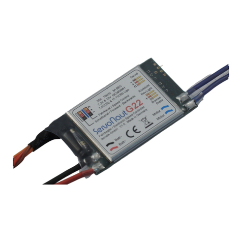
ProjectAir SC520 User manual

1
MPPT Solar Charge Controller
5 STAGE CHARGING 12/24/48V MULTI-CHEMISTRY
SC520
SC540
P/No. SC520, SC540
Pictured: SC520

2
1. Safety Tips
• Please ensure the instructions are read prior to any installation.
• Keep instructions in a safe place for future reference.
• Do not expose to rain, snow or liquids of any type, SC520 and SC540 are designed for indoor use only.
• Beware of any nearby electrical equipment that may interfere with installing this device.
DonotconnectanyACsourcestothecontrollerasitmaycauseare/explosionandwillpermanently
damage the device.
• Always check the battery polarities before making a connection. The positive terminal of a battery goes
into BAT+ and the negative into BAT-.
• The controller is not designed to run without a battery voltage reference. In the event of replacing
/servicingthebattery,alwaysdisconnectthesolarinputrst(orfullycoverthepanels),thenreplace/
service the battery.
• Solar panels can generate high voltages and currents, make sure your solar panels are completely
covered from sunlight during installation.
• Keep this product out of reach of children.
• Always install fusing or circuit breakers on the input positive and output positive circuits.
• Connecting wires to this device can generate sparks, please wear proper insulation gear
while installing this device.
• Thiscontrollerisanegativegrounded(positiveswitching)type.
• Always take the total length of wire into consideration and use the correct wire size, see below for a
table of recommended wire size for various current loads.
•Leadacidbatteriescanbedangerous.Ensurenosparksoramesarepresentwhenworkingnear
batteries.
Maximum
Cable
Distance
Solar Input Current
10A 20A 30A 40A
2m 12AWG
4mm2
10AWG
6mm2
10AWG
6mm2
8AWG
10mm2
Wire AWG
& Cross
Section
Area
3m 12AWG
4mm2
10AWG
6mm2
8AWG
10mm2
6AWG
16mm2
5m 10AWG
6mm2
8AWG
10mm2
6AWG
16mm2
6AWG
16mm2
7m 10AWG
6mm2
6AWG
16mm2
6AWG
16mm2—

3
2. Product Features
• 5 Stage charging ensures the battery is charged to the optimum level.
• AdvancedMPPTtechnologytoimprovechargingefciencyindifferentweather
and temperature conditions.
• Tempered glass screen with sturdy aluminium housing.
• Selectable battery chemistry types, including AGM, GEL, WET and Lithium.
• Auto recognition of 12V/24V/48V battery system voltage.
• Protects your battery from discharge at night. Under low light or no light conditions, the solar panel
voltage could be less than the battery voltage. The controller contains circuitry which prevents current
owingbackfromthebatteryandintothesolarpanel.
• Multi charging protections against reverse polarity, over-voltage and over-temperature.
• Withtheuseofabatterytemperaturesensor(optional),thecontrollerwillcompensatecharging
voltageswhenthebatterytemperaturebecomestoohigh(ForLeadacidonly).
• Supports remote display via Bluetooth for monitoring additional parameters, such as charging
watt-hours, charging current and solar input voltage.

4
3. Device Diagram
4. Wiring Instructions
# Description # Description
1 LCD Display Screen 8 RS485 Communication Port
2LEDIndicator(PV,CHARGE,FAULT) 9Solar Input Terminals
3 Cancel/Return Button 10 Battery Terminals
4 Increase/ Previous Button 11 External Temperature Sensor Port
5 Decrease/ Next Button 12 EPO Contacts Port
6 Enter/ Select Button 13 Output Dry Contacts Port
7InstallationMountingHoles
12
3 4 5 6
77
8910 11
12
13
#
Description
#
Description
1LCD Display Screen 8RS485 Communication Port
2LED Indicator (PV, CHARGE, FAULT) 9Solar Input Terminals
3Cancel/Return Button 10 Battery Terminals
4Increase/ Previous Button 11 External Temperature Sensor Port
5Decrease/ Next Button 12 EPO Contacts Port
6Enter/ Select Button 13 Output Dry Contacts Port
7Installation Mounting Holes
12
3 4 5 6
77
8910 11
12
13
#
Description
#
Description
1LCD Display Screen 8RS485 Communication Port
2LED Indicator (PV, CHARGE, FAULT) 9Solar Input Terminals
3Cancel/Return Button 10 Battery Terminals
4Increase/ Previous Button 11 External Temperature Sensor Port
5Decrease/ Next Button 12 EPO Contacts Port
6Enter/ Select Button 13 Output Dry Contacts Port
7Installation Mounting Holes
4. Insert the bare wire side of the cable to the
terminal, and tighten the screws.
5. Check the wiring condition and put the wiring
cover plate back.
3. Unscrew the terminals completely,
before inserting any wiring leads.
1 & 2: Remove the wiring cover plate,
and put it aside..

5
PV--PV+ BAT+BAT- TEMP
SENSOR
Solar Panel
Ba�ery
Fuse
5. Wiring Sequence
1. Connect the positive battery wire followed by the negative battery wire.
2. Connect the positive solar array input wire followed by the negative solar array input wire
(makesureyoursolarpanelsarefullycoveredtopreventelectricalshock).
3. Connecttheexternaltemperaturesensor(optional)toitsterminalshownabove,andplacethesensor
on the side of a battery.
The controller is not designed to run without a battery voltage reference. In the event of replacing/servicing
the battery, always disconnect the solar input or fully cover the panels, then remove/replace the battery.

6
6. Operation
6.1 Pre-operation Check
Please check the installation and wiring carefully before operation:
Step 1: Make sure the SC520/SC540 is installed correctly and steadily.
Step 2: Make sure the cable layout and distancing are meeting the requirements of all the
equipment in the system.
Step3:Makesurethegroundwireisproperlyconnectedrmlyandreliably.
Step4:MakesureBatteryandPVarraycircuitbreakers(orfuses)aredisconnected.
6.2 Power ON Test
Make sure the battery voltage and solar panel voltage are within the permissible range before turning
on the breaker:
Step 1: Reconnect circuit breaker or fuse for the battery.
Step 2: Reconnect circuit breaker or fuse for the PV array.
Step 3: Set the parameters according to the setup wizard.
Step 4: Observe the LED light to check if the SC520/SC540 is working normally.
6.3 Power OFF
TheSC520/SC540willstillcontainresidualpowerandheatafterpowerOFF.
Toavoidelectricshockorburnrisk,pleasecooldowntheSC520/SC540for5minutesafterpowerOFF.
Then uninstall the SC520/SC540 with protective gloves:
Step 1: Turn off the circuit breaker for the solar panel.
Step 2: Turn off the circuit breaker for the battery.
6.4 System Initial Setup
EntertheSetupWizardforinitialsetupwhentheSC520/SC540ispoweredonforthersttimeorfactory
settings are restored. You can also reset the Setup Wizard through the Parameter Set interface.
*if you don’t want to change the default values, simply press to prompt ,
thenpress toconrm.
Enter the
Setup Wizard?
Time Set
2019-03-10 13:26
Battery_Type
0- GEL/0PzV
Battery_AH
200AH
Conrm?

7
6.5 Charging Stages
TheSC520/SC540multi-stagedalgorithmisdesignedtochargethebatterywithhighefciency
and reliability.
SoftStart(Stage1)–Thecontrollerwilldeliver½ratedcurrentuntilthebatteryvoltageisover11.5VDCor
10-minutetime-out,thenturntotheBulk(Boost)Stage.
Bulk(Boost)Charge(Stage2A)–UtilisingMPPTtechnology,thecontrollerwilldelivermaximumrated
current until batteries rise to absorption level.
*EqualizationCharge(Stage2B)–OnlyapplicabletoFlooded,WETandAGMmode.Every30days,itwill
skip boost and automatically run equalization to rejuvenate the internal battery cells.
AbsorptionCharge(Stage3)–thecontrollerwilldeliverconstantvoltagebasedonthebatterychemistry
settinguntilthechargecurrentislessthan3A,thenthecontrollerwillturntooatchargemode.
FloatCharge(Stage4)–Onlyapplicabletonon-lithiumbatteries.Whenthebatteryisfullycharged,itwill
reducethevoltagetooatvoltagesettingasperchemistryselecttokeepthebatterytoppedup.
RecycleCharge(Stage5)–After10daysofFloatcharge,thecontrollerwillreturntobulkchargeand
charge the battery to set voltage point.
Battery Voltage
Charging Current

8
7. Menu Introduction
...
STARTUP STANDBY:
REAL-TIME
STATUS
1ST LEVEL
MENU:
PARAMETER
SETTING/
INFORMATION
QUERY
2ND LEVEL
MENU:
PARAMETER
SETTING/
INFORMATION
DISPLAY
3RD LEVEL
MENU:
FURTHER
SETTING
BOOT
ANIMATION
Power ON,
MCU
bkght on
PROJECTA
PRODUCT
CODE
SC520/SC540
10s,
10s
2019-03-02 13:26
Chr On
U_PV73.4V
P_OUTPUT 0.0W
U_BAT 13.2V
I_CHG 0.0W
Normal
Working State:
5s loopdisplay
(looping period
can be adjusted
in seg)
Alarm State:
When errors
happen with
SC520/540, the
alarm status will be
displayed instead
MPPT Err 13
OFF)
ERROR:
stops hing
MPPT Wrn 02
U_BAT_LV
WARNING:
Wrning,
hing
g Info U_PV 69.9V
t 800W
U_BAT 24.9V
I_CHG30W
T_inside 54
T_BAT_EXT N/A
>Ss Info E_Tod
E_Yesterd
E_Month
E_Yer
E_Tot
>Crrent Error 0 error
0 wrning
Re 2019-03-02 13:26
Chr On
2019-03-02 5:30
MPPT Err 09
……
Set e
Be
Set o
Set Log
>Reset d
Info >Mode
>So Ver
>User >Sn Set
& Tie Set
Ver
>Se ber
>Reset Devie
Log
o
>Reset
e d
s info
Yesterds info
Seet the Month nd e with
for spei ds s
Seet the Month with for
spei Months s
To Sr
MPPTErr 08
PSU_LV_HD
If fts orred, press to see the ft ode
MPPT Err 09
PSU_LV
Ft Dets
Reset Devie
r?
<ModeNer>
<SeNer>
Sore Ver
V……
Hrdwre Ver
V……
Please see secn 6.3
for detailed
instrucn for
parameter se
Set
>Ad Set
>EQ Set

9
BEGIN
Change the
parameters?
Press the , the corresponding bit flashes, press
the to change the value
Press the to confirm the value, then repeat the
same steps for other parts
Completed?
Press the , the cursor appears on the
rightmost bit of the parameter
Save?
Use the
Default Se�ng?
press to prompt ,
then press to confirm.
NO
NO
YES, Press
No
parameters
chan
ged, back to
the
original display
Successful
Se�ng?
Successful se�ng Prompt Successful se�ng Prompt
Next Se�ng
NO
YES
YES
7.1 Start-Up
After power on, the LCD display will light up the backlight, show a boot animation and then display the
following information in sequence.
7.2 Real-Time Working Status
After the initial startup, if the controller is working normally, the display will show the real-time
device working status.
*5s default display looping period, manually turning pages with will standby on the current page for 30s as default.
*Changing the Parameter Setting required the password, the initial password is “1000”. The password can be adjusted in Factory Set interface.
PROJECTA
PROJECTA
SC520
SC540
10s
10s
ForSC520:
ForSC540:

10
Interface Display Description Default
Setting Setting Range
>Para System SYS_Module_Addr Systen Module Parallal
Address 1 1~4
>Para_Mode
OutCtrl_CHG External Control
(Read Only) 0- Disable 0 - Disable
1 - Enable
RlyCtrl_Cong Output dry contact
conguration 0- Disable 0 - Disable
1 - Alarm Switch
Silent_Mode_EN Silent Mode 0-Disable 0-Disable
1-Enable
Force_Charger Forced Charge Mode 0-Disable
0- Disable
1- BAT_Level_12
2- BAT_Level_24
3- BAT_Level_48
EPO_DRY_IN_EN Remote Switch 0-Disable 0- Disable
1- Enable
>Para_Battery
>Basic Set Battery_Type
Battery Type
(Select 3,5,6 to unlock
EQ Setting)
GEL/OPzV
0- GEL/ OPzV
1- AGM
2- Lead-Carbon
3- Flooded
4- Customize
5- Traction
6- OPZS
7- BMS
Battery _AH Battery Capacity 200Ah 20~2000Ah
>Advanced Set
U_Absorp_CHG Absorption Charge
Voltage 14.1V
Refer to 9. Controller
Specication for setting
range
U_Float_CHG Float Charge Voltage 13.7V
Refer to 9. Controller
Specication for setting
range
BAT_OV_Warn Overvoltage Warning
12VDC: 14.9V
24VDC: 29.8V
48VDC: 59.6V
12VDC:
(U_AVE_CHG +0.2)~17.0V
24VDC:
(U_AVE_CHG +0.4)~34.0V
48VDC:
(U_AVE_CHG +0.8)~68.0V
CHG_MAX_Current
Maximum Charging
Current
(Reset this setting every
time the battery capacity
changed)
Rate_CHG_CUR 3~Rate_CHG_CUR
(Max=40A)
Min_Bulk_Time Minimum Bulk Charge
Time 120min 1~600min
Max_Absorp_Time Maximum Absorption
Charge Time 8h 1~240h
Auto_CHG_Cycle Equalization Cycle Time 240h 24~2400h
CHG_T_Compensate Charging Temperature
Compensation 0-Disable 0-Disable
1-Enable
CHG_TEMP_Coef
Charging Temperature
Compensation
Coefcient Setting
12VDC: -18mV
24VDC: -36mV
48VDC: -72mV
12VDC: -30~0mV/°C
24VDC: -60~0mV/°C
48VDC: -120~0mV/°C
BAT_OT_WARN_G
ate
Battery Setting Over
Temperature Warning 55°C 35~65°C

11
Interface Display Description Default Setting Setting Range
>Para_Battery
>EQ Set (Only for FLD,
Traction and OPZS
batteries)
EQ_Command Equalization Charge 0-OFF 0-OFF
1-ON
U_EQ_CHG Equalization Charge
Voltage
12VDC: 15.6V
24VDC: 31.2V
48VDC: 62.4V
12VDC: 15.5V~16.3V
24VDC: 31.0V~32.6V
48VDC: 62.0V~65.2V
EQ_Sustain_Time Equalization Charge
Time 30min 30~90min
>Change Password >Change Password Change Password for
Parameter Set Interface 1000
>Setup Wizard Refer to Section 6.4
> Reset Parameter Reset User_Para Restore Default Settings
7.4 User Control
TheSC520/SC540congurationcanbeadjustedaccordingtocustomerneeds,including
system date & time, backlight and automatic page turning time.
Interface Display Description Default Setting Setting Range
>Screen Set
Backlight_KeepOn Backlight Constant On 0-Disable 0-Disable
1-Enable
Page_Turn_Auto
Real-time Status
Automatic Page Turning
Time
5s 3~30s
>Data & Time System Time Setting
8 Alarm Code
The SC520/SC540 has two alarm levels:
• Warning: the SC520/SC540 is still charging normally, but with warning alarm.
Example:
•Fault:theSC520/SC540hasanerrorandchargingstops.
Example:
8.1 Alarm Code Chart
Alarm Level ID Display Description Quick Troubleshooting
Fault
01 V_bus_OV Solar input voltage has exceeded
the controller’s maximum rating
Lower the solar panel’s total
voltage connected to the
controller
02 U_BAT_OV
Battery output voltage has
exceeded the controller’s
maximum rating
*Check whether there is an
external voltage applied
to the battery
*Check the SC520/SC540 Battery
setting is consistent with the
battery conguration
03 U_BAT_OV_HD
MPPT WARN 02
U_BAT_LV
MPPT Err 09
PSU_LV

12
Alarm Level ID Display Description Quick Troubleshooting
Fault
04 Buck_Short Cut Battery short circuit Check and adjust the battery
wiring
05 I_Buck1_OC
The bulk stage charging current
has exceeded the controller’s
maximum rating
Lower the maximum charging current setting
in the parameter setting
>Para_Battery
>Advanced Set
>CHG_MAX_Current
07 T_Board_OT The controller has exceeded the
ambient temperature limit
Ensure the controller is placed
in a well-ventilated area
09 PSU_LV The solar panel’s power is too low Check the conguration of the
solar panels.
10 PSU_LV_HD
11 Sam_HD_Fault Sampling Failure
Please contact your dealer
12 EEPROM_Fail The read and write function of
the controller is abnormal
13 EPO(Remote OFF) The 2P phoenix terminal is not
connected to the controller EPO.
Insert the 2P phoenix terminal into the EPO
of the charger. If the fault alarm is still on,
please contact your dealer
Warning
01 U_BAT_OV The battery voltage has exceeded
the maximum rating
Adjust the battery parameter setting to be
consistent with the battery conguration
02 U_BAT_LV The battery voltage is too low
Check the battery conguration and wait for
the battery to be charged to normal voltage
range
03 Cur_Limit The charging current has
exceeded the maximum rating Check the battery parameter setting
04 BAT_UnConnect The connection between the
battery and the controller failed.
Check the wiring and the circuit
breaker between the battery and
the controller
06 T_BAT_OT
The surrounding temperature
around the temperature
sensor is too high
Check the sensor is not near a source of heat.
Battery may be faulty if it is too hot
08 TypeSet_Mismatch_Err
The controller model setting is
not consistent with the controller
conguration
Check and adjust the model setting
14 NTC_Board_Fault The NTC temperature sensor
board inside the charger is faulty. Please contact your dealer.
8.2 Battery Temperature Sensor
As an option, the unit provides a port to connect the external battery temperature sensor. If it is used, the
unit will optimise the charging performance based on the battery temperature.

13
Controller
Parameter Specications
Model No. SC520 SC540
System Wiring
Grounded Negative Grounded
Battery System
Voltage 12/24/48VDC
No-load Loss 1mA/12VDC, 3mA/24VDC. 5mA/48VDC
Max Solar Input
Voltage <100Voc <100Voc
Rated Solar Charge
Current 20A 40A
Max Solar Input Power
300W/12V
600W/24V
1200W/48V
600W/12V
1200W/12V
2400W/48V
Operating
Temperature -40°C~+70°C
Net Weight 1.4kg
Communication RS485, Bluetooth
Controller
Dimensions 205*160*68.5mm
Dry Contact 30VDC/2A
IP Rating IP31
Battery Voltages Battery Parameters
Battery Types CUSTOM GEL LFP (Default) AGM WET
Bulk Charge Voltage Default (LFP) 14.1V/28.2V/56.4V 14.2V/28.4V/56.8V 14.4V/28.8V/57.6V 14.7V/29.4V/58.8V
Bulk Charge
Time-out 12 hours (then transition to absorption stage)
Absorption Charge
Voltage Default (LFP) 14.1V/28.2V/56.4V 14.2V/28.4V/56.8V 14.4V/28.8V/57.6V 14.7V/29.4V/58.8V
Absorption Stage
Time-out 10 hours (then transistion to oat stage)
Float Charge Voltage Default (LFP) 13.5V/27.0V/54.0V 13.5V/27.0V/54.0V 13.5V/27.0V/54.0V 13.7V/27.4V/54.8V
Recycle Stage Return
Voltage Default (LFP) 12.8V/25.6V/51.2V 13.3V/26.6V/53.2V 12.8V/25.6V/51.2V 12.8V/25.6V/51.2V
Auto-Temperature
Compensation Default Setting: -3mV / °C / cell
Custom Mode Setting
Battery Voltage 12V 24V 48V
Customised Default Bulk Charge Voltage 14.2V 28.4V 54.0V
Customised Bulk Charge Voltage Setting Range 13.0~14.5V 26.0~29.0V 52.0~58.0V
Customised Default Float Charge Voltage 13.7V 27.4V 53.2V
Customised Float Charge Voltage Setting Range 13.0~14.0V 26.0~28.0V 52.0~56.0V

14
10. Controller Dimensions
SC520 & SC540
Product Dimensions: 205 x 160 x 68.5mm
Installation Area Dimensions: 160 x 150mm
InstallationHoleSize:5x5mm

15
11. Installation
Good ventilation can guarantee the normal operation of equipment. Please always guarantee there
is enough clearance around SC520/SC540 upon installation. Please refer to following image for
minimum clearance.
Pleasechooseaatandcleansurfaceforinstallation,markthepositionforthe4mountingpointanduse
the 4 x M5 mounting screw sets supplied. Please tighten the screws properly and make sure all 4 screws
are installed to avoid falling. Install the SC520/SC540 as close to the batteries as possible. This will reduce
the potential for voltage drop and ensure maximum performance of the equipment.

16
IS523
Issue 01.23
WARRANTY STATEMENT
Brown&WatsonInternationalPtyLtd(“BWI”)of1500FerntreeGullyRoad,Knoxeld,
Vic.,telephone(03)97306000,fax(03)97306050,warrantsthatallproductsdescribedin
its current catalogue will under normal use and service be free of failures in material and
workmanshipforaperiodofthree(3)yearsfromthedateoftheoriginalpurchasebythe
customer as marked on the invoice. This warranty does not cover ordinary wear and tear,
abuse, alteration of products or damage caused by the purchaser.
To make a warranty claim the consumer must deliver the product at their cost to the
original place of purchase or to any other place which may be nominated by either
BWI or the retailer from where the product was bought in order that the warranty
assessment may be performed. The consumer must also deliver the original invoice
evidencing the date and place of purchase together with an explanation in writing as
to the nature of the claim.
In the event that the claim is determined to be for a minor failure of the product then BWI
reserves the right to repair or replace it at its discretion. In the event that a major failure is
determined the consumer will be entitled to a replacement or a refund as well
as compensation for any other reasonably foreseeable loss or damage.
This warranty is in addition to any other rights or remedies that the consumer may have
underStateorFederallegislation.
IMPORTANT NOTE
Our goods come with guarantees that cannot be excluded under the Australian Consumer
Law. You are entitled to a replacement or refund for a major failure and compensation for
any other reasonably foreseeable loss or damage. You are also entitled to have the goods
repaired or replaced if the goods fail to be of acceptable quality and the failure does not
amount to a major failure.
Distributed by
AUSTRALIA
Brown & Watson International Pty. Ltd.
KnoxeldVictoria3180
Phone:(03)97306000
Fax:(03)97306050
NationalTollFree:1800113443
NEW ZEALAND OFFICE
Grifths Equipment Ltd.
19 Bell Avenue,
Mount Wellington,
Auckland 1060, New Zealand
Phone:(09)5254575
This manual suits for next models
1
Table of contents
