WaterGeneral RD-322 Supplement

INSTALLATION & SERVICE MANUAL
Reverse Osmosis + DI Water Systems
Model:
RD-322 6-Stage RO+DI system, 260 GPD, single output
Note:
System must be maintained and serviced using manufacturer’s original replacement filters and parts. Using
other brands of replacement filters may shorten the life of RO membrane and damage the auto-shut-off valve.
Made by: WaterGeneral Mfg. Co.
Made in U.S.A.
PRODUCT SPECIFICATION
System Requirements
•Working pressure: 50 to 80 psi feed water pressure required, if below 50 psi, a booster pump is
recommended. We have a RO system with booster pump assembly. If the input pressure is above 80
psi, you MUST put a pressure regulator to reduce the pressure below 80 psi.
•Working temperature: 100 ~ 40 deg. F ( 37 ~ 4 deg. C )
•pH range: 2-11
•If feed water has hardness level above 300 ppm, we recommend putting a water softener prior to the RO
system.
•If feed water has iron, rust problem, we recommend putting a iron filter prior to the RO system.
•If feed water has bacteria problem, we recommend putting an ultra violet sterilizing system prior to RO
system.
Filter Service Life
•1st Stage Sediment filter: Recommend changing every 6 ~12 months.
•2nd Stage Carbon block filter: Recommend changing every 6 ~12 months.
•3rd Stage Carbon block filter: Recommend changing every 6 ~12 months.
•4th & 5th Stage TFC membranes: Recommend changing every 2~3 years.
•6th Stage Inline DI filter (RD-322 only): Recommend changing when TDS reading is undesirable.
Warranty
•1 year Limited Warranty on parts, components. Filters are not under warranty. System must be
maintained and serviced using manufacturer’s original replacement filters and parts. Using 3-party
replacement filters may shorten the life of RO membrane and damage the auto-shut-off valve.
Purification Processes/ Filter specifications
Removes microbiological contaminants like Cysts (protozoan), inorganic/Radiological contaminants like
Barium, Cadmium, Copper, Chromium (hexvavalent), Chromim (trivalent), Fluoride, Lead, Radium
226/228, Selenium, etc.
Ammonia, Arsenic, chloramines, chlorine, copper, lead, nitrate, phosphate, silica, hardness, calcium,
magnesium, other dissolved solids.

2
Thank you for choosing Watergeneral Reverse Osmosis Water Systems. You now own a superb Reverse Osmosis (RO) +
Deionization (DI) system that effectively reduce most contaminants, organic and inorganic compound, unwanted taste and
odor from tap water. It is designed to transform your tap water into distill water.
Read carefully and follow the instruction in this manual before proceeding with actual installation. Failure to do so could
result in personal injury or damage to the equipment or other properties. Be sure to follow any special plumbing codes in
your area.
CHECK LIST:
1. Reverse Osmosis+DI Unit
2. for (RD-167) which includes water storage tank, 4 gallon outside volume (holds 3.2 gallons @60psi)
3. Installation kit consists tank ball valve, drain saddle valve, feed water adapter, feed water needle valve, faucet
assembly(for RD-167) , tubing, tube inserts
4. Installation manual
INSTALLATION KIT:
1. Drain saddle clamp
2. ¼” tubing
3. Bottom filter housing wrench
4. ½” feed water adapter
5. garden hose adapter, 3/4H x 1/4" tube
6. chrome ball valve for water supply
7. side-mount float valve
8. Ball valve, ON/OFF 1/4"
RECOMMENDED TOOLS LIST
Variable speed drill 1/8” 1/4”, 7/16”, 1/2”, and 5/8” drill bit
5/8, 9/16 open-end wrench, or adjustable wrench, pliers Phillips screwdriver
Utility knife, or scissor Teflon tape
OPERATING PARAMETER
•Working pressure: 40 to 80 psi feed water pressure required. If input pressure is below 40 psi, a booster pump or a
permeate pump is needed. We have a RO system with built-in permeate pumps, and we also carry booster pumps.
If the input water pressure is above 80 psi (you must use a pressure regulator to step down the pressure). We
also carry small pressure regulators just for the RO system.
•Working temperature: 100 ~ 40 deg. F ( 37 ~ 4 deg. C )
•If feed water has hardness level above 300 ppm, we recommend putting a water softener prior to the RO system.
•If feed water has iron, rust problem, we recommend putting an iron filter prior to the RO system.
•If feed water has bacteria problem, we recommend putting an ultra violet sterilizing system prior to RO system.
WARNING: Do not use this RO+DI system alone to treat water with bacteria problem or water source with unknown
quality.
WARNING: Do not connect HOT water source to this unit.
WARNING: Incorrect installation will VOID the warranty.
WARNING: Input pressure must not exceed 80 psi. Pressure regulator must be installed to reduce pressure.

3
About the system
Reverse Osmosis process is a separation process. Tap water enters the system, and it is separated at the 4th stage
membrane filter. Pure water would go to one side, and the other side carrying all the minerals is purged to the drain. The
ratio of purified water to drain water for single membrane is about 1:4 (depends on water pressure). That means for every
gallon of water you use, it will drain 3 gallons. The drain is required for the RO process to work. If the drain is
intentionally shut off, all the minerals will be accumulated inside the membrane, and it would permanently damaged the
membrane filter.
All Reverse Osmosis units require purging of water when it’s producing water.
Double membrane design:
The advantage of double membrane design is to double the capacity and halves the drain. A typical single membrane RO
drains about 4 gallons for every gallon of pure water. Double membrane RO only drains 2 gallons for every gallon of
pure water.
Production rate: The system requires higher operating pressure than typical single membrane. The system uses two 150
GPD (gallons per day) RO membranes in series. The actual production rate will depend on water input pressure,
temperature, and water chemistry. At optimal condition the membrane will make 280 GPD, but on average, it would
make about 220 gallons per day at 60psi and 240 GPD at 70psi.
Drain rate: The drain rate of the system is set at 1100 mL/min. using a flow restrictor. This drain rate is constant,
independent of input pressure.
How to attach tubing to the system
There are two types of fittings in the system. Compression and quick-connect
compression fitting connections: first, you
must unscrew the compression nut off the
fitting, then pass the tubing through the
compression nut about 1”, then screw on to
the fitting, then use a 5/8” wrench to tighten
the nut until the thread is not visible. Don’t
over-tighten it.
Quick-connect fitting:
To connect tubing- begin with fresh cut or new tubing, then push the
tubing all the way into the fitting. It has to go through the O-ring that’s
inside. Then it will seal itself.
To disconnect tubing- push the collet (the plastic ring near the opening)
with one hand and pull the tubing using the other hand.
Connect to garden hose or laundry room hose
1. You can connect the ¾” garden hose adapter directly to a hose valve or to a hose.
2. Make sure the black rubber gasket is seating at the bottom of the thread. Then screw on the adapter
directly to the hose or hose valve. Use pliers if necessary.
3. The other end of the adapter is a Quick-connect fitting ¼”. So just push in the ¼” tubing about ½”
into the fitting, then it will seal itself. (Note: to disconnect tubing, just push the plastic ring against
the fitting, then pull out the tubing)
4. Then for other tubing connection, please refer to the picture shown next page. The drain line can
just run to open drain or to the laundry room drain.
5. You can also use a hose Y-connector to connect to the hose valve to have two outlets, so one for
the system and one for your laundry room washer.

4
INSTALLATION QUICK VIEW
Easy-way Installation:
1. Use the garden hose
adapter to connect to the
water supply. Connect to
garden hose valve, garden
hose, or laundry room hose
valve (cold side)
2. Connect the drain line to a
open sink, laundry room
drain, floor drain. Or
connect the drain line to a
drain pipe using the drain
clamp.
3. Connect the pure water
output to a on/off ball
valve, or to a float valve
for your large container.

5
TROUBLE SHOOTING
1. the cone washer we provided is straight, not spiral). Use Teflon tape on threaded parts to prevent leaks. Then tighten the
connection.
2. For Solid Copper riser: Same procedure as flex tubing except you must cut a piece of the riser tube about 3/ 4” to 1” so the
adapter can fit between faucet and riser tube. Use Teflon tape to prevent leaks.
3. Install the angle needle valve to adapter if you have not done so in procedure #4.
4. For connecting red tubing to angle needle valve, refer to the photo below. Then push tubing through the brass nut, then the
sleeve, then put plastic insert inside the tubing, then push sleeve against the insert, then screw on the brass nut. Don’t over
tighten it. But it has to be tight.
1. feed water adapter ½” connect to
base of kitchen faucet
1. buy a ½ pipe to ½” pipe hose
2. ½ to ½” nipple fitting.
3. adapter.
4. your existing faucet pipe
•Many times, it is easier to use the existing
cone washer than using the new one.
•If there is not enough space under the sink
base, or it’s difficult to get to, you can
disconnect the riser from the cold-water valve
side. If the fitting size does not match, buy
size-changing fittings, or buy a new flex riser
with matching sizes.
•Many times, it is easier to buy an additional
stainless steel braded flex riser and a ½”
nipple to put in between the bottom of the
faucet male thread and the feed water adapter
(Don’t buy the spiral type) so you can easily
put the feed water adapter between two risers.
This is the EASIEST way. Spend additional
$5 on the riser may save you a lot of time.
Feed water adapter with Ball valve
1. put Teflon tape on the thread, put only 3 turns
2. push tubing through the nut,
3. push tubing all the way into the connection,
4. screw on the nut tight using a wrench
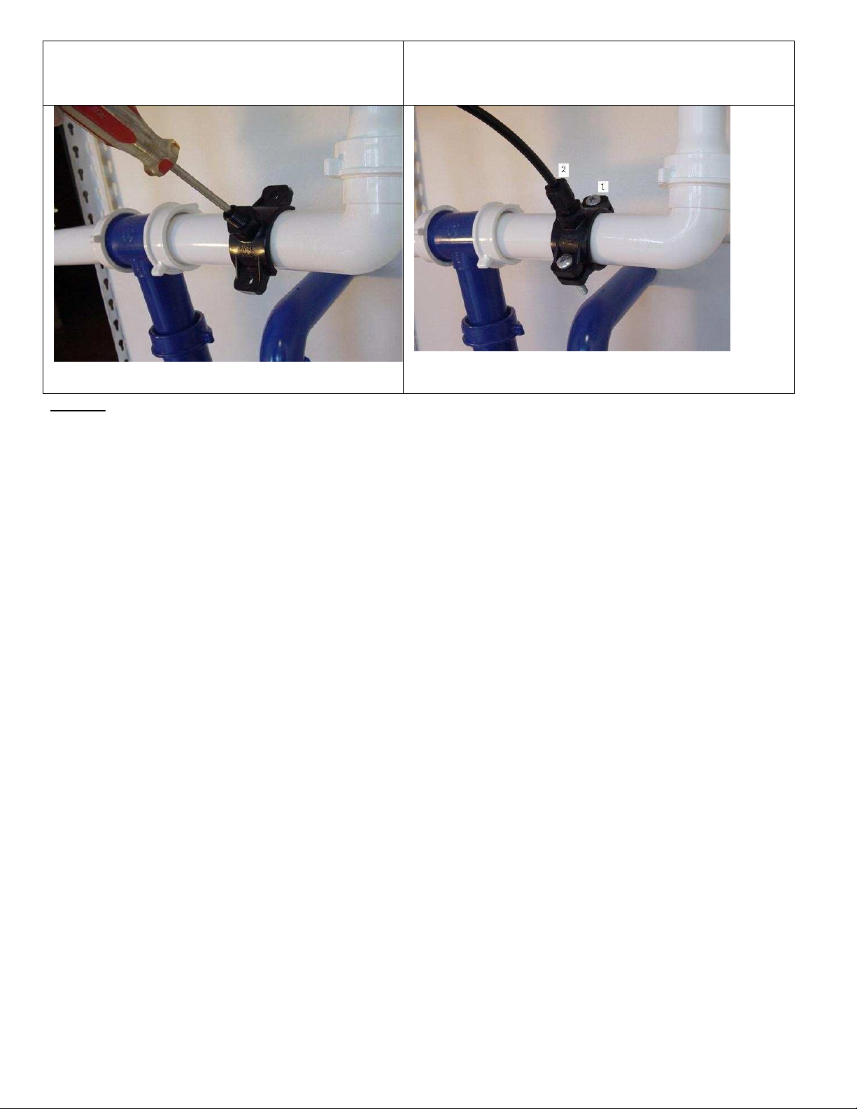
STEP 4: MOUNTING THE DRAIN SADDLE VALVE (don’t put in shaded area)
Position the drain
saddle in desired location, mark spot. You need to consider
available space for drain tubing
6
The drain saddle valve should fit most standard drain pipe. It
should be installed above the trap and on the horizontal pipe
(1) or vertical pipe (2).
DON’T put on position (3), (4), or blue section
Drill 1/ 4” hole into the drainpipe above the water line of the pipe.
Clean the surface of the pipe.
Pear off the sticky foam pad, then align the center hole around the
drilled pipe hole. Then tape it.
Align the drilled hole in the drain pipe with the drain saddle
using a drill bit or narrow screwdriver
put the complementary piece and clamp them together with the
two bolts. (1) Tighten the two bolts evenly. (2) Connect tubing
STEP 5: SYSTEM START-UP
1. Make sure all tubing are not kinked.
2. After the water supply tubing, drain tubing and pure water tubing are connected, turn cold water supply main
valve on slowly. Also turn input ball valve ON. Turn on pure water output. When the system is pressurized,
check for leaks. If a leak is found, tighten the connection.
3. Wait 5 minutes, the water should start dripping out of the pure water output, and then wait 10 more minutes to
allow water to flow through the system, and air inside the system can be purged.
4. Let pure water drain out for about 1 gallon before start using the water.
5. Job Well Done!
NOTE: Check for leaks daily for the first week after installation.

7
* For more detailed tech support notes & troubleshooting go to www.watergeneral.com
NOTE: Turn off the system before servicing.
Installation Troubleshooting
PROBLEM POSSIBLE CAUSE SOLUTION
No or low water production
1. Feed water valve is not turn on
2. Tubing is kinked 1. Turn on feed water valve
2. Straighten the tubing
Leak at filter housing 1. Housing is not tighten
2. Damaged or misaligned O-ring
3. Housing has cracks
1. Use filter housing wrench to tighten housing
2. realign or replace O-ring
3. Replace housing
Leak at fitting thread 1. Not properly tighten
2. Fitting has cracks 1. Use Teflon tape, re-tighten
2. Replaced it
Milky/Cloudy water 1. Air in system/filters 1. This is normal, continue use it for 2 weeks
Noise from drain
Saddle valve mounted too high 1. Lower the saddle valve
When system is making water, waste water to
drain is normal, when storage tank is full, drain
should stop
Troubleshooting
PROBLEM POSSIBLE CAUSE SOLUTION
Vibrating noise or very loud
high pitch noise 1. From the auto shut-off valve
2. auto-shut-off valve is hitting
against the steel plate
1. If the noise is unbearable, shut-off valve
should be replaced.
2. Use bubble wrap or paper to wrap
around the valve so it doesn’t hit the plate
Drain water never shut off
1. Auto shut-off valve is worn out
or becoming ineffective
2. Water supply pressure is 50 psi
or below
3. Cold water temperature
4. Filters are clogged up
1. Replace auto shut-off valve
2. Booster pump is needed for input water
pressure less than 50
3. the system makes water slower at cold
temperature
4. Replace filters
Low water production 1. Clogged filters
2. Kinked tubing
3. Clog flow restrictor
1. Replace filters
2. Straighten the tubing
3. Replace flow restrictor
Note: Clogged filters: How do you know if the filters are clogged up? For the pre-filters, sediment filters and carbon
filters; check the pressure difference before and after the filters. If there is significant difference in pressure that means
the filter is clogged. Turn OFF tank valve and cold water main valve then open the RO faucet to depressurize the system,
then disconnect the tubing after the bottom three pre-filters, then turn ON the cold water main valve. If you get very
strong water pressure, (as strong as water going into the system) then the bottom 3 pre-filters are not clogged. If the water
pressure is much smaller, unlike a burst of water pressure, then the bottom 3 pre-filters need to be replaced. Note:
Checking a clogged membrane uses different method. Use a water quality meter TDS meter to check the condition and
performance of the RO membrane (4th stage filter)
Note: Clogged flow restrictor: When you disconnect the black tubing going into the saddle valve, and the RO system is
in the processing of making water (by turning on the RO faucet), there should be a small steady flow of drain water. If
you do not get any drain water, the flow restrictor may be clogged, then you need to replace a new flow restrictor ASAP,
and discontinue using the system.
NOTE: If after few days of running the system, the problem comes back, then you may need to replace a new tank.

8
Changing Filters Procedures
•Shut off the system by turning off the water supply, and turn off the tank valve, open
the spigot to depressurize
•Prepare a towel under the unit for water spills
•Use a filter wrench (part no. 566) or use hands to open the filter housing, unscrew it
from right to left. To open is clockwise looking from the top.
•Throw away the used filter, and clean the inside of the housing by rinsing or
scrubbing it with dish soap.
•Check condition of the O-ring. It should be replaced every 3 years to prevent leak
•Place the new filter inside the filter housing. For carbon filters, the rubber gaskets
should be on both ends.
•Put some Vaseline or silicon-based O-ring lubricant on the side of the housing thread
and the O-rings (optional procedure)
•Use a filter wrench or both hands to screw the housing back by turning it from left to
right (Don’t lay down the unit when turning it, the unit should be standing upright to
prevent the o-ring or filters from misalignment)
•Repeat the above steps for other filters
Changing Membrane Procedure
•Lift the membrane housing from the U-clips, and remove the tubing from the membrane fitting (the inlet side of the membrane
housing, or the side with the membrane housing cap). Unscrew the membrane housing cap off (counter-clockwise)
•Use pliers to pull the membrane out of the membrane housing, and discard the used membrane.
•Put some Vaseline or lubricant on the small black O-rings. Insert the new membrane into the membrane housing (THE SIDE WITH
DOUBLE BLACK O-RINGS SHOULD GO IN FIRST) Push the membrane all the way in (some force is required to make sure the
membrane is all the way in). Put some Vaseline or silicon based lubricant to the side of the housing threads.
•Screw the membrane-housing cap back (clockwise). Make sure O-ring is in place. Connect the tubing to its elbow fittings.
•Turn on the water supply and tank valve to restart the system. Check for leaks, if there is a leak, tighten the cap
•Wait 2 to 3 hours for the tank to be filled then you must drain the first tank of water by opening up the spigot to flush the system.
LIMITED ONE-YEAR WARRANTY
1. What your warranty covers:
WaterGeneral Reverse Osmosis+DI Systems are warranted to the original owner to be free of defects in material and
workmanship from the date of manufacture for two years as follows:
a. Manufacturer will, within one year of purchase, replace the defected parts (excluding filters) at no charge.
b. The replaceable filters are not warranted since the service life of replaceable filter varies with local water conditions
and thus not warranted.
2. Conditions of Warranty:
a. System must be maintained and serviced with the manufacturer original replacement parts and filters. The
performance of your drinking water system is directly related to the conditions of the water been treated and the
particular application in which it is used. Therefore, manufacturer’s liability is limited to the cost of repair of the
RO+DI system. The manufacturer is not liable for incidental or consequential damages of any kind. Systems
must be installed and operated in accordance with manufacture’s recommended procedures and guidelines.
3. What WaterGeneral Reverse Osmosis+DI Systems will not do:
a. Warranty is void if product failure or damage results from freezing, neglect, misapplication, fouling with sediment
or scale or failure to operate the system in accordance with the instructions contained in this manual.
b. The following operating conditions must also be followed for this warranty to be valid
•The hardness of the water cannot exceed 7 grains per gallon or 120 ppm.
•No iron can be present in feed water. Or iron should be removed from feed water.
•The pH of the water must not be lower than 3 or higher than 11
•Feed water Total Dissolved solids TDS should not exceed 1000 ppm

9
•Feed water temperature between 90 F and 45 F or (32C and 5 C)
4. Obtaining Warranty Service:
For Warranty service, obtain a Return Merchandise Authorization (RMA #) number from the manufacture or distributor.
You can also contact our technical support department to obtain the RMA # or visit our web site at
http://www.WaterGeneral.com or email your request to tech@WaterGeneral.com
5. Limitations and exclusions:
Manufacturer will not be responsible for any implied warranties, including those of merchantability and fitness for a
particular purpose. Manufacturer assumes no liability whatsoever for any incidental and consequential damages, including
loss of revenue, loss of time, travel expenses, inconvenience, and any damage caused by the equipment and its failure to
function properly.
SERVICE RECORD:
DATE OF PURCHASE:
DATE OF INSTALLATION/SERVICE:
Service Date Date Date Date Date
1st stage sediment
2nd stage carbon
3rd stage carbon
4th stage membrane
5th stage DI filter (clear)
6th stage inline carbon
This manual suits for next models
1
Table of contents
Other WaterGeneral Water System manuals

Popular Water System manuals by other brands


Miele professional
Miele professional UG 70-60/80 operating instructions

Pentek
Pentek UVS-110 Installation and operating instructions

Xylem
Xylem FLOJET 5000 Series manual

Everpure
Everpure Single Head EV9272-19 Specification sheet

Everpure
Everpure Quad-XC Cartridge EV9628-09 Specification sheet

AmeriWater
AmeriWater SILEX 00M20821 Operation & maintenance manual


