16
The ideal environment for algal growth is when there
are periods of zero chlorine. Algae blooms can take
less than a day to turn a pool green.
At the first sign of adversity, the algae population goes
into a reproduction phase to produce spores. The size
of these spores is less than 0.2 microns. D.E. filters
are able to filter 5+ microns and sand filters are only
able to filter 20+ microns.
11. ALGAE
A common problem for any type of pool is algae growth. There are 24,000 known types of algae, all
distinguishable by being single-celled organisms capable of photosynthesis (they produce their own
food), mitosis (all cells can divide) and meiosis (reproduction is possible by combining with other algal
cells).
Algae will die from doses of chlorine as low as 0.05 ppm concentration, but spores can resist chlorine
levels up to 10 ppm. Domestic salt chlorinators cannot achieve such a level.
Spores, however, cannot tolerate copper salts as copper attaches to the shell or endospore
preventing germination. Hence, the most effective algaecides contain copper salts.
For a few black algal spots, suspending 50 grams (1.7 ounces) of stabilised chlorine in a weighted nylon
bag over the trouble spots may remove them.
For a more serious algae problem, it is advisable to follow the procedure below:
1. Lower pH below 7, generally by the addition of up to 2 litres (4 pt) of pool acid, as this is an
essential part of reducing algae resistance.
2. About 4 hours later, add a copper treatment to attain a 1 ppm copper level in the pool. One
economical method is to mix about 1 heaped tablespoon of copper sulphate (approximately 70 grams or
3 ounces) dissolved in 10 litres (approximately 3 gal) of water spread around the pool. But the use of
any commercial copper-based algaecide will do.
Note: Do not swim in the pool for at least 24 hours, as the copper treatment may discolour
hair and clothing.
3. After about 12 hours, a stainless steel brush and a garden hose fitted with a brass jet gurney
(available from hardware stores) can be used to remove algae from the pool walls.
TO LOWER TOTAL ALKALINITY
USING LIQUID POOL ACID
(HYDROCHLORIC ACID)
50,000
395mL
580mL
1.22L
1.60L
2.00L
2.40L
2.82L
3.20L
3.60L
4.05L
75,000
554mL
1.20L
1.85L
2.40L
3.05L
3.65L
4.25L
4.85L
5.45L
6.10L
100,000
790mL
1.60L
2.45L
3.20L
4.00L
4.80L
5.65L
6.40L
7.20L
8.10L
Table A
POOL VOLUME IN LITRES
TO RAISE TOTAL ALKALINITY
USING SODIUM BICARBONATE
INCREASE
ppm
10
20
30
40
50
60
70
80
90
100
50,000
893gm
1.70Kg
2.60Kg
3.40Kg
4.30Kg
5.20Kg
6.00Kg
6.80Kg
7.80Kg
9.00Kg
75,000
1.34Kg
2.60Kg
3.90Kg
5.20Kg
6.50Kg
7.80Kg
9.10Kg
10.40Kg
11.70Kg
13.40Kg
100,000
1.79Kg
3.40Kg
5.20Kg
6.80Kg
8.60Kg
10.40Kg
12.00Kg
13.60Kg
15.60Kg
18.00Kg
Table B
POOL VOLUME IN LITRES
LOWER
ppm
10
20
30
40
50
60
70
80
90
100
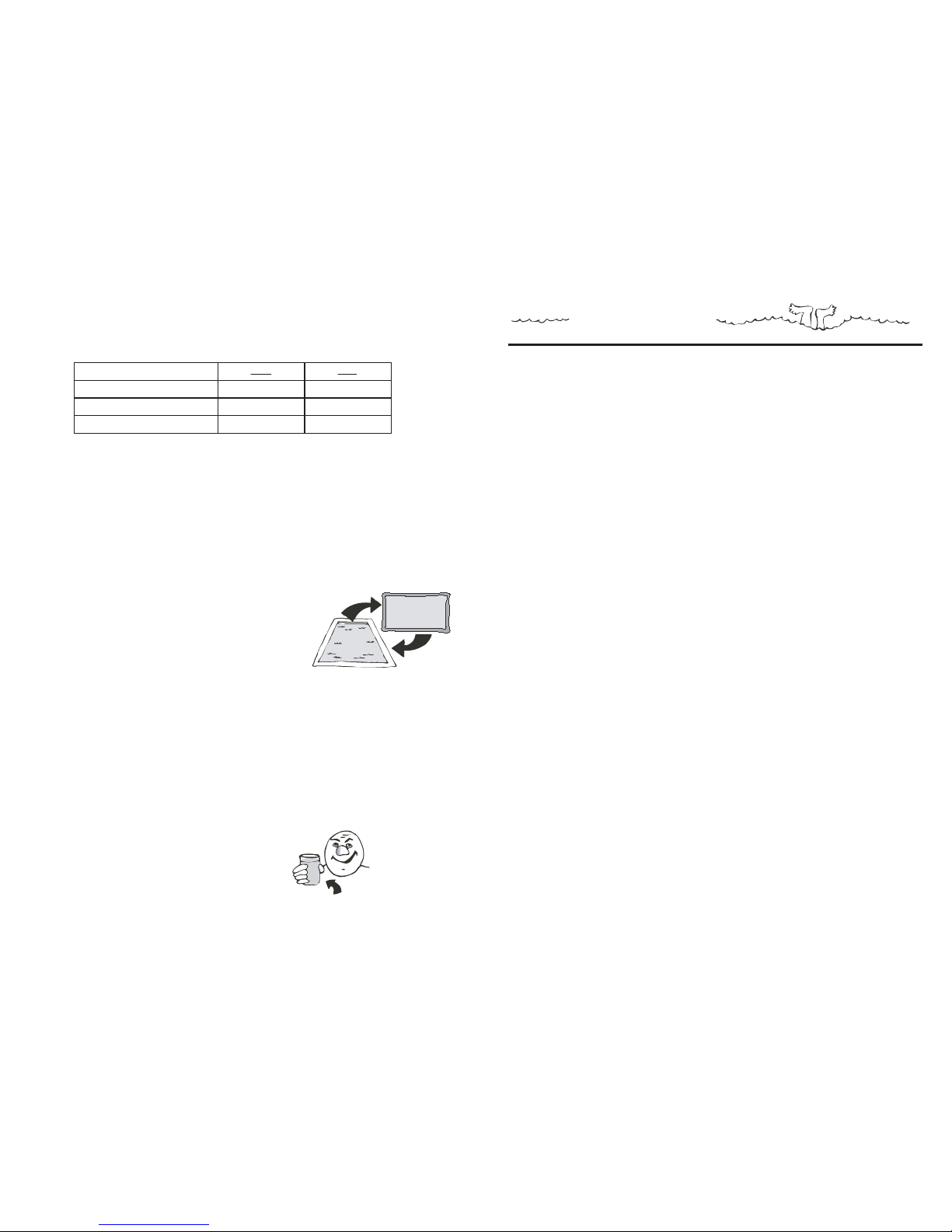
U.S.
Measurement
Conversions:
To convert from
Litres to Gallons:
x 0.2642
To convert
from Kilograms
to Pounds:
x 2.205
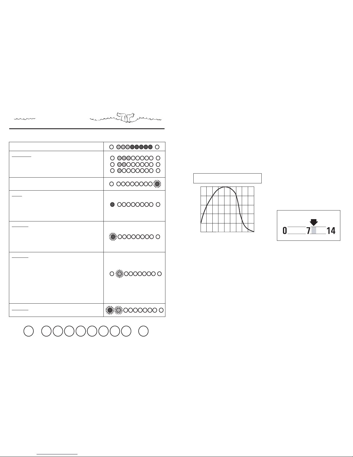
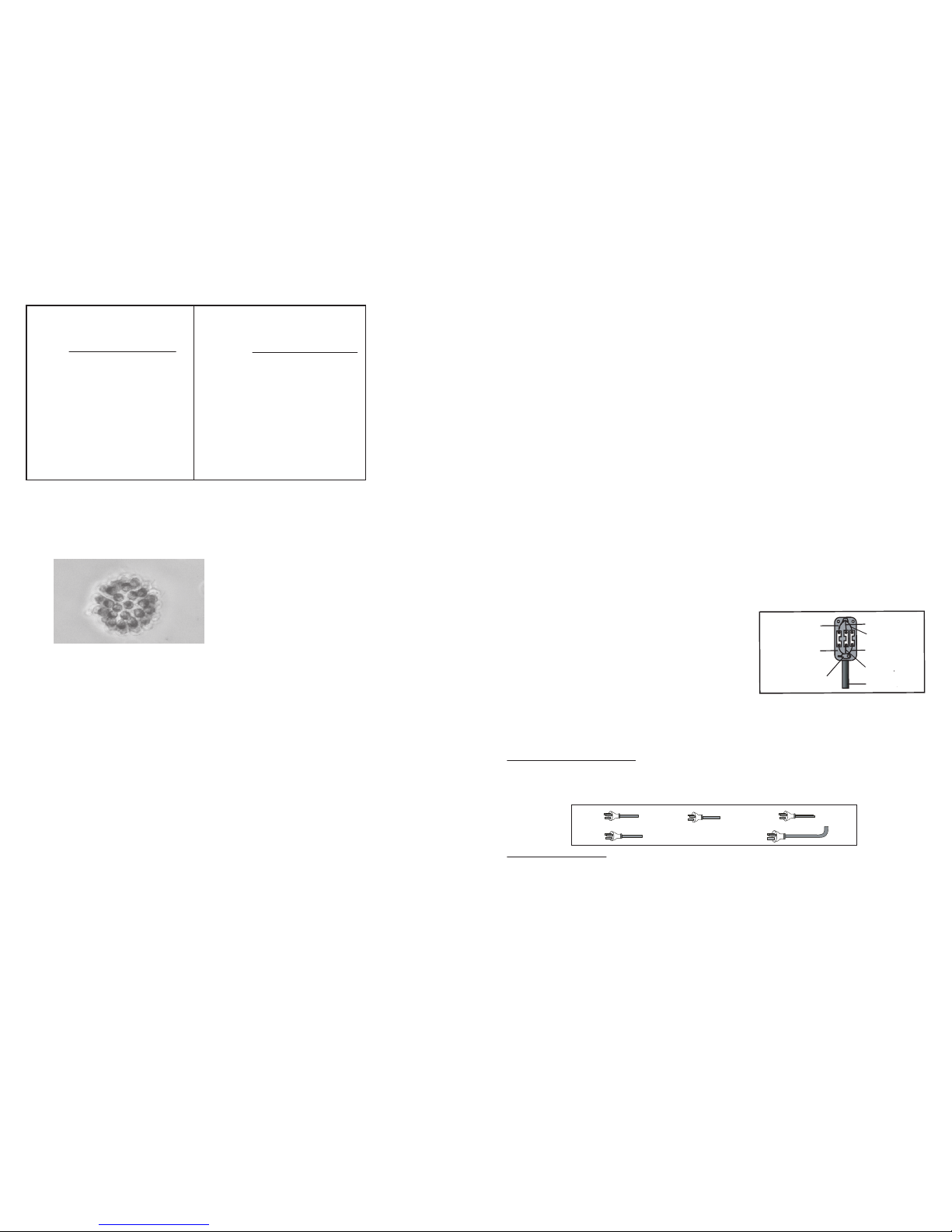
A microscopic view of algae
Copyright © Watermaid Pty Ltd 5
(iii) MOUNT THE WATERMAID® POWER SUPPLY
The WATERMAID® Power Supply MUST be installed AT LEAST 3M (10 ft) from the inside wall of the
pool. Ideally it should be enclosed within a splash-proof housing (e.g. filter box) and mounted in a
position that complies with local regulations.
1. Locate a suitable position for the WATERMAID® Power Supply which allows for box dimensions of 240
mm wide x 320 mm high x 130 mm deep (9.4 x 12.6 x 5.1 ins. respectively). [Leave a gap of at least
20 mm (0.8 ins.) at the top of the WATERMAID® Power Supply to any structure or fitting above].
2. For mounting onto brick work:
a) Drill two 8 mm (0.3 in) diameter holes, 30 mm (1.2 in) deep, that are 156 mm (6.1 in) apart and
level.
b) Insert two 8 mm (0.3 in) diameter wall plugs into the holes drilled.
c) Place the screws (provided) into the holes of the bracket (provided) and tighten.
3. For mounting onto timber:
a) Drill two 4 mm (0.2 in) diameter holes into the timber, 30mm (1.2 in) deep, that are 156 mm (6.1
in) apart and level.
b) Place the screws (provided) into the holes of the bracket (provided) and tighten.
4. Lift the WATERMAID® Power Supply onto the bracket ensuring that it is secure on the wall.
N.B: The appliance must be installed such that the supply plug is accessible.
(iv) INSTALL THE WATERMAID® CELL
Before installing the Cell, unplug the pump and WATERMAID® Power Supply. This is advisable so that
the filter will not start inadvertently if a time clock already exists. Also, close off any valves if the filter
and pump are below pool surface level or if there are no valves, block off the inlet and outlet with
rubber stoppers. The WATERMAID® Cell should then be installed as per the model-relevant installation
diagram given on page 6, 7 or 8.
(v) ATTACH THE CELL TO POWER SUPPLY
If the wires are connected incorrectly, the unit may appear to work for a brief period but may damage
the Cell and Power Supply if left uncorrected.
(vi) CONNECT TO THE POWER OUTLET
Australian and European models: [refer to diagram below]
1. Insert the pump plug into the socket at the base of the WATERMAID® Power Supply.
2. For a time clock Power Supply, insert the WATERMAID® plug into the electrical power outlet.
3. For a non time clock Power Supply, insert the WATERMAID® plug into an external time clock and plug
the time clock into the electrical power outlet.
US and Canadian models:
1. For 110VAC models, insert the WATERMAID® Power Supply's plug into the electrical power outlet.
The outlet must be wired by a qualified electrician so that no power is available to the unit if the pump
is off.
2. For 220VAC models, the WATERMAID® Power Supply’s power cord should be hard wired by a
qualified technician to run in conjunction with the pump.
If the Cell and Power Supply are not already connected,
use a screwdriver to connect the Cell wires to the wires
contained in the black junction box at the base of the
WATERMAID® Power Supply as follows:
Red or Brown - TO - Red or Brown
Black or Blue - TO - Black or Blue
White - TO - White
PUMP
TIME CLOCK POWER SUPPLY
STANDARD
POWER SUPPLY
EXTERNAL
TIME CLOCK
Cell cord
White wire
Black/Blue wire
White wire
Holding
Clamp
Red/Brown wire
Red/Brown wire Black/Blue wire
Copyright © Watermaid Pty Ltd
POWER
OUTLET