Waterous 70-35-GP User manual

12/7/2017
Operation Guide
Applies to Waterous Model
70-35-GP Rotary
Rev 5
Unit Serial Number ______________________
Waterous Company
125 Hardman Avenue South
South St. Paul, MN 55075 USA
651-450-5000
Fax: 651-450-5090
www.waterousco.com

Waterous 70-35-GP Rev 5
Page 2 of 24
Warnings, Cautions, and Notes
Warning
A warning alerts you to a procedure, practice or condition that may result in death or long
term injury to personnel or destruction of equipment.
Caution.
A caution alerts you to a procedure or condition that may result in serious
damage to equipment or its failure to operate as expected
Note: A note points out important information. Failure to read the note may not result in
physical harm to personnel or equipment. It may waste time and money.
Revision History
Revision
Date Issued
Comments
---
04/2005
Original Release
1
9/29/2006
Logo chg, reformatted, T/S guides added, added
Manual Auto-sync pic,
2
9/6/2007
Updated Service parts list
3
5/20/10
Updated per ECR 136
4
5/26/10
Compressor changed
Disclaimer: These instructions are guidelines only and in no way meant to be definitive. During installation, standard safety
precautions and equipment should be used where appropriate. Because the tools used and the skill/experience of
the installer can vary widely, it is impossible to anticipate allconditions under whichthis installationis made, or to
provide cautions for all possible hazards. Proper installation is the responsibility of the purchaser. All bolts,
setscrews, and belts must be checked prior to start-up AND after the initial operation. Damages due to poor
installation are the responsibility of the installer.
Waterous reserves the right to make modifications to the system without notice

Waterous 70-35-GP Rev 5
Page 3 of 24
Table of Contents
SECTION 1. OPERATING INSTRUCTIONS .....................................................................................4
A. Multiple Uses...............................................................................................................................4
B. Water Pumping Operations..........................................................................................................4
C. Foam Solution Operations............................................................................................................5
D. Compressed Air Foam Operations ...............................................................................................5
SECTION 2. SHUT-DOWN PROCEDURE........................................................................................7
SECTION 3. SERVICE AND MAINTENANCE...................................................................................8
A. Maintenance Schedule.................................................................................................................8
B. Maintenance Items.......................................................................................................................8
SECTION 4. CAFS NOZZLE / FLOW RATE / HOSE COMBINATIONS.............................................9
A. Nozzles........................................................................................................................................9
B. Foam Concentrate Ratios.............................................................................................................9
C. Hose............................................................................................................................................9
SECTION 5.SUGGESTED GUIDELINES FOR THE PRODUCTION OF MID-RANGE
COMPRESSED AIR FOAM.........................................................................................10
A. 1” Hose Diameter Jacketed........................................................................................................10
B. 1-1/2” Hose Diameter.................................................................................................................10
C. 1-3/4” Hose Diameter.................................................................................................................11
D. Master Stream ...........................................................................................................................12
SECTION 6. TROUBLESHOOTING - CAFS....................................................................................13
SECTION 7. TROUBLESHOOTING – PUMP..................................................................................17
SECTION 8. TROUBLESHOOTING – BASIC ENGINE ...................................................................21
SECTION 9. CONDITIONAL 5-YEAR WARRANTY POLICY...........................................................24
Figure(s)
Figure 1 Manual Auto-sync Controls.......................................................................................................4
Figure 2 Unit Dimensions and Controls.................................................................................................22
Figure 3 Basic CAFS Schematic...........................................................................................................23

Waterous 70-35-GP Rev 5
Page 4 of 24
SECTION 1. OPERATING INSTRUCTIONS
Check the following fluid levels daily or prior to starting unit:
•Engine oil
•Compressor oil
•Foam concentrate
•Onboard water supply
A. Multiple Uses
The Waterous portable compressed air foam unit can be operated in several pumping
modes: water only, foam solution without compressed air and compressed air foam.
NOTE: Monitor compressor instruments during any and all operations.
Figure 1Manual Auto-sync Controls
B. Water Pumping Operations
All unit operations begin with pumping water. These steps must be followed for operations
involving pumping water, foam solution or compressed air foam.
Connect the hose to the discharge port.
Prior to starting the engine, the Auto-Sync control should be in the UNLOAD, a position which
allows the air compressor to "free wheel" without pumping air.

Waterous 70-35-GP Rev 5
Page 5 of 24
•If pumping water from an onboard booster tank, fully open the tank to pump valve. If
pump from an overboard source, the tank to pump valve should be fully closed.
•If so equipped, turn on the main electrical power switch to the CAFS unit.
•To start the engine, open the throttle to approximately 1/4, close the choke if necessary,
move the ignition switch to the "ON" position, then to the start position to crank the
engine until it starts.
•Throttle-up to desired pressure. If pump pressure is absent, it will be necessary to prime
the pump utilizing the Waterous Manual Primer.
•To prime,
a) Open the1/4 turn Priming valve.
b) Pump primer until water comes out of the outlet hose
c) When the water discharge pressure gauge rises, the pump is primed.
d) After prime is achieved, close the Primer valve.
•Open thedischarge valve and throttle-up to desired pressure.
CAUTION:
Running the unit for extended periods with a dry fire pump can cause damage to
the pump.
C. Foam Solution Operations
Follow the instructions above for water pumping operations.
a) Attach the foam concentrate supply line to the FPS and foam pail, then open the
concentrate metering valve in the supply line.
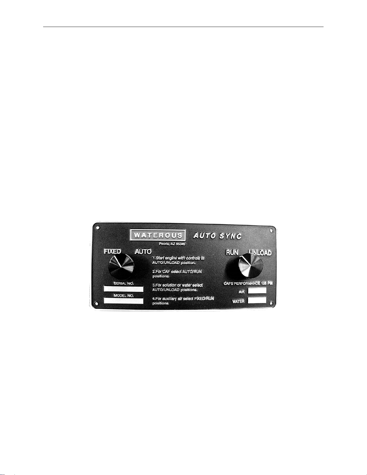
b) Set the pump to the desired pressure (approximately 125psi).
c) Water and foam concentrate will now exit the FPS into the hose line. Foam
concentrate will be less than 1.0% under normal operating conditions.
d) If the foam produced is too dry, slowly close the metering valve towards 0 (0 equals
fully closed and 5 equals fully open).
e) Following any use of the FPS with foam concentrate, and prior to shut down for any
extended period, the foam concentrate metering valve should be closed, and clean
water should be allowed to flow through the FPS to clean itself. The check valve in
the foam concentrate supply line should be periodically removed and rinsed to insure
proper foam concentrate flow.
D. Compressed Air Foam Operations
Follow the instructions above for foam solution operations. Safe operations dictate the
presence of foam concentrate in the water stream prior to the injection of compressed air. If
foam concentrate is not present, a condition known as "slug flow" will occur. This is where
unmixed water and air is discharged through a nozzle in an erratic manner.

Waterous 70-35-GP Rev 5
Page 6 of 24
Discharge pressures for compressed air foam operations typically range between 80 and 100
PSI in a flow state. Set water discharge pressure at the desired level.
NOTE: Compressed air foam does not have the hydraulic characteristics of plain water or
foam solution. Therefore, standard pump hydraulics practices do not apply to CAFS
operations.
1. Move Auto-Sync control to the AUTO position. Air pressure as shown on the air pressure
gauge should rise to within plus or minus 5% of the water discharge pressure. The Auto
Sync system will balance the air and water pressures throughout a range of 40 PSI up to
120 PSI. Optimal compressed air foam system performance occurs at discharge flow
pressures of 80-100 PSI.
2. Open the discharge gate valve approximately 1/4 to 1/2 open. The foam expansion ratio
is set by controlling the amount of foam solution entering the discharge stream. High
solution flows restrict the amount of air admitted and result in lower expansion or "wet"
foam. To produce higher expansion or "drier" foam, simply gate back the amount of
solution admitted.
3. Fully open the air valve to admit compressed air into the discharge, then adjust the
solution flow to produce the desired foam consistency.
Foam is formed during the transition through the hose. To produce acceptable finished
foam, sufficient hose length must be provided on the discharge. Refer to Section on
“Suggested Guidelines for the Production of Mid-Range Compressed Air Foam” for
minimum hose lengths for CAFS operations.
WARNING
Nozzle reaction force is significantly increased at the time the nozzle valve is opened in
compressed air foam operations. OPEN CAFS NOZZLES SLOWLY!

Waterous 70-35-GP Rev 5
Page 7 of 24
SECTION 2. SHUT-DOWN PROCEDURE
1. Close air valve(s)
2. Turn off Foam proportioner by moving the selector handle to zero
3. Flow clear water through dischargehose(s) until no bubbles are present
4. Close discharge valve
5. Move Auto Sync control to UNLOAD
6. Shut engine down
WARNINGS:
•Compressed air can be dangerous. Read and understand the operating
instructions for the Waterous compressed air foam unit and individual
components prior to operating.
•DO NOT use the compressed air foam unit as an air source for SCBA or any
breathing air supply.
•Discharge outlets that are capped, hose lines that are valved and charged may
contain compressed air. Relieve all pressure BEFORE attempting to remove
any caps, fittings, nozzles, or to perform maintenance to prevent serious
personal injury.
•Nozzle reaction force is significantly increased at the time the nozzle valve is
opened in compressed air foam operations. OPEN CAFS NOZZLES SLOWLY!
•Operating the compressed air foam unit with water and compressed air
pumped through a discharge without foam concentrate will create a potentially
dangerous condition known as "slug flow"; where unmixed pockets of water
and air are passed through the nozzle, causing erratic nozzle reaction.
•For compressed air foam operations, use only fire hose that is rated at 200 PSI
or higher working pressure.
•The unit operator should have a thorough understanding of "Boyle's Law" (The
law of compressed gases) prior to operating the compressed air foam unit.
•It is recommended that the operator wear/use full safety equipment (i.e. gloves,
eye protection) on the fire grounds and when operating this system.

Waterous 70-35-GP Rev 5
Page 8 of 24
SECTION 3. SERVICE AND MAINTENANCE
Refer to the included manuals for service and maintenance information on the following individual
components:
•Engine
•Air Compressor
•Foam Proportioner
A. Maintenance Schedule
Check oil level
and for oil leaks
Change Oil
Filter
Daily or After Each Use
X
Annually
X
X
Every 24 Months
X
X
B. Maintenance Items
COMPRESSOR
Part#
AIR FILTER:
CO45002 (1)
2030040
COMPRESSOR OIL
ISO 68 Non-foaming
ENGINE
(refer to Engine Manual for Maintenance Schedule)
Part#
AIR PRE-FILTER:
692520 (4)
6030037
AIR FILTER:
692519 (4)
6030036
OIL FILTER:
492932 (4)
6030038
FUEL FILTER:
691035 (4)
6030039
SPARK PLUGS
491055 (4)
6030040
ENGINE OIL:
Refer to Engine Manual
BELTS
Part#
PUMP:
8MGT-1120-12 (3)
1030027
COMPRESSOR:
8MGT-896-12 (3)
1030024
(1) = Donaldson (2) = Mann & Hummel (3) = Gates
(4) = Briggs & Straton

Waterous 70-35-GP Rev 5
Page 9 of 24
SECTION 4. CAFS NOZZLE / FLOW RATE / HOSE
COMBINATIONS
A. Nozzles
Compressed air foam can be discharged through various types and sizes of nozzles. Fog
nozzles break-down the bubble structure of the foam, resulting in "wetter" or reduced
expansion foam. The preferred way to make foam is utilizing smooth bore nozzles with a
given hose diameter. Smaller tips will discharge "wetter" foam.
B. Foam Concentrate Ratios
Proportioner settings of 0.2% and 0.6% are typically adequate to produce compressed air
foam that is formed in a hose line and used on Class A combustibles. Higher settings will
result in”drier" appearing foam. Lower settingsmay result in "slug flow" or discharge pulsation
caused by insufficient foam concentrate in solution to form foam in the hose line.
C. Hose
Utilize fire hose that is rated by the hose manufacturer for use with CAFS. Since the foam is
formed during its transition through the hose line, it is important to utilize the minimum
recommended hose lengths, unless a static mixer is utilized. There is significantly less friction
and head loss with compressed air foam as compared to water or foam solution. Hence,
effective fire streams can be achieved with longer hose lays. Refer to the Suggested
Guidelines for the Production of Mid-Range Compressed Air Foam.
NOTE: Compressed air foam systems have the ability to produce foam of shaving cream
consistency. While this type of foam is highly stable and possesses a long drain time,
it is essential to ensure that the foam will release sufficient water to extinguish a fire
in a direct attack situation. This type of foam is typically suited for defensive
operations such as exposure protection, barriers or fuels pre-treatment.

Waterous 70-35-GP Rev 5
Page 10 of 24
SECTION 5. SUGGESTED GUIDELINES FOR THE
PRODUCTION OF MID-RANGE COMPRESSED AIR
FOAM
A. 1” Hose Diameter Jacketed
1 GPM to 1 CFM
½” Tip Solution Flow: 15 GPM (56.78 LPM)
Air Flow: 15 CFM (0.42 m3/min)
Disch. Pressure: 100-150 PSI (6.804 - 10.206 BAR) (689.5 - 1034.25 KPA)
Min/Max Hose Length: 35’ to over 400’ (10.668 – 121.92 meters)
2 GPM to 1 CFM
½” Tip Solution Flow: 30 GPM (113.56 LPM)
Air Flow 15 CFM (0.42 m3/min)
Disch. Pressure: 100-150 PSI (6.804 - 10.206 BAR) (689.5 - 1034.25 KPA)
Min/Max Hose Length: 35’ to over 400’ (10.668 – 121.92 meters)
1 GPM to 1 CFM
¾” Tip Solution Flow: 20 GPM (75.71 LPM)
Air Flow: 20 CFM (0.56m3/min)
Disch. Pressure: 100-150 PSI (6.804 - 10.206 BAR) (689.5 - 1034.25 KPA)
Min/Max Hose Length: 35’ to over 200’ (10.668 – 60.96 meters)
2 GPM to 1 CFM
¾” Tip Solution Flow: 40 GPM (151.41 LPM)
Air Flow: 20 CFM (0.56m3/min)
Disch. Pressure: 100-150 PSI (6.804 - 10.206 BAR) (689.5 - 1034.25 KPA)
Min/Max Hose Length: 35’ to over 200’ (10.668 – 60.96 meters)
B. 1-1/2” Hose Diameter
1 GPM to 1 CFM
1” Tip Solution Flow: 30-40 GPM (113.56 – 151.41 LPM)
Air Flow: 30-40CFM (0.84 – 1.12 m3/min)
Disch. Pressure: 100-150 PSI (6.804 - 10.206 BAR) (689.5 - 1034.25 KPA)
Min/Max Hose Length: 100’ to over 800’ (30.48 – 243.84 meters)

Waterous 70-35-GP Rev 5
Page 11 of 24
2 GPM to 1 CFM
1” Tip Solution Flow: 60-80 GPM (227.12 – 302.82 LPM)
Air Flow: 30-40CFM (0.84 – 1.12 m3/min)
Disch. Pressure: 100-150 PSI (6.804 - 10.206 BAR) (689.5 - 1034.25 KPA)
Min/Max Hose Length: 100’ to over 800’ (30.48 – 243.84 meters)
1 GPM to 1 CFM
1-3/8” Tip Solution Flow: 50-60 GPM(189.27 – 227.12 LPM)
Air Flow: 50-60 CFM (1.4 – 1.68 m3/min)
Disch. Pressure: 100-150 PSI (6.804 - 10.206 BAR) (689.5 - 1034.25 KPA)
Min/Max Hose Length: 100’ to over 800’ (30.48 – 243.84 meters)
2 GPM to 1 CFM
1-3/8” Tip Solution Flow: 90-120 GPM (340.68 – 454.24 LPM)
Air Flow: 50-60 CFM (1.4 – 1.68 m3/min)
Disch. Pressure: 100-150 PSI (6.804 - 10.206 BAR) (689.5 - 1034.25 KPA)
Min/Max Hose Length: 100’ to over 800’(30.48 – 243.84 meters)
C. 1-3/4” Hose Diameter
1 GPM to 1 CFM
1” Tip Solution Flow: 30-40 GPM (113.56 – 151.41 LPM)
Air Flow: 30-40 CFM (0.84 – 1.12 m3/min)
Disch. Pressure: 100-150 PSI (6.804 - 10.206 BAR) (689.5 - 1034.25 KPA)
Min/Max Hose Length: 100’ to over 1400’ (30.48 – 426.72 meters)
2 GPM to 1 CFM
1” Tip Solution Flow: 60-90 GPM (227.12 – 340.68 LPM)
Air Flow: 30-50 CFM (0.84 – 1.4 m3/min)
Disch. Pressure: 100-150 PSI (6.804 - 10.206 BAR) (689.5 - 1034.25 KPA)
Min/Max Hose length: 100’ to over 1400’ (30.48 – 426.72 meters)
1-3/8” Tip Solution Flow: 50-90 GPM(189.27 – 340.68 LPM)
Air Flow: 50-80 CFM (1.4 – 2.24 m3/min)
Disch. Pressure: 110-150 PSI (7.4844- 10.206 BAR) (758.45- 1034.25 KPA)
Min/Max Hose Length: 100’ to over 700’ (30.48 – 213.36 meters)
NOTE: With 1-3/4” hose lengths of 100’-250’ (30.48 – 76.2 meters), up to 90-120 GPM
(340.68 – 454.24 LPM) of water and 40-100 CFM (1.12 – 2.8 m3/min) of air may be
utilized as a highly effective initial attack flow.

Waterous 70-35-GP Rev 5
Page 12 of 24
D. Master Stream
1” Tip Solution Flow:
90-120 GPM (340.68 – 454.24 LPM)
Air Flow: 60-80 CFM (1.68 – 2.24 m3/min)
1-3/8” Tip Solution Flow:
100-150 GPM (378.53 – 567.80 LPM)
Air Flow: 70-100 CFM (1.96 – 2.8 m3/min)
1-1/2” Tip Solution Flow:
120-200 GPM (454.24 – 757.06 LPM)
Air Flow: 80-120 CFM (1.68 – 3.36 m3/min)
1-3/4” Tip Solution Flow:
180-250 GPM (681.35 – 946.33 LPM)
Air Flow: 120-150 CFM (3.36 – 4.2 m3/min)
2” Tip Solution Flow:
250-450 GPM (946.33 – 1703.39 LPM)
Air Flow: 200 CFM (5.6 m3/min)
Disch. Pressure: 120-150 PSI (8.1648 – 10.206 BAR) (827.4 – 1034.25 KPA)

Waterous 70-35-GP Rev 5
Page 13 of 24
SECTION 6. TROUBLESHOOTING – CAFS
The following instructions may refer to options or equipment that you may not have purchased with your
system.
Observed
Symptom Probable Cause Suggested Remedy
Lack of air pressure
from compressor
Lack of air supply to
clutch (for air-clutch
systems) Repair air leak or re-establish air supply
Compressor not
engaging No PTO engagement Confirm OK TO PUMP light is on, if not check wiring for damage or
disconnected wire, check PTO.
Compressor
engaging. No air
supply to
discharges or
insufficient air
supply.
Auto-Sync switches not
in correct position.
Confirm 40 PSI in UNLOAD position (200 CFM systems) and 50+ in run
position.
Smaller compressors have lower UNLOAD pressures.
Verify when in FIXED/RUN whether pressure reflects 145-150 PSI
(electric valves) Verify
there is power to the air
solenoid and check
operationof solenoid.
Air discharge solenoid not working.
Repair/replace solenoid
Air solenoid working - leak between solenoid and discharge. Repair leak.
Air check valve defective
Replace or correct installation.
Trim valve out of
adjustment Refer to trim valve instructions
Restricted minimum
pressure valve Clean rust or debris from valve
Air plumbed before
discharge valve seal Relocate to discharge side of discharge valve
Incorrect air line size Size according to discharge and replace line with correct size.
System functioning
correctly, pressure
gauge reading
obviously incorrect.
Gauge malfunction, air
line detached Check for air leaks, replace gauge
FIXED has
pressure but AUTO
has
no pressure
No water supply to
balance valve. Check line for proper installation, with no kinks or obstructions.
Refer to trim valve instructions.
Air discharge
pressure too high
Red hose circuit
(compressed air control)
has leak or is
disconnected.
Repair leak or attach hose

Waterous 70-35-GP Rev 5
Page 14 of 24
Observed
Symptom Probable Cause Suggested Remedy
System overheating
Inadequate water flow
through cooler Ensure adequate water flow through pump. Check Y strainer for
obstruction, clean and reinstall Drain and flush cooler water tubes
Adequate water flow
through cooler.
On-board tank used for cooling for a prolonged period - watertoo hot to
effectively cool the compressor. Locate source of lower temperature water.
Check oil level -
Adjust level to half of the sight glass on level surface.
Low compressor oil
level:
Check the hydraulic lines for kinks
Change oil filters
Temperature sending
unit and or gauge circuit
malfunction. Check wire connections at sending unit
High Oil
Consumption
Overfull compressor oil Adjust level to half of the sight glass on levelsurface.
Excess of 200 CFM air
flow (on 200 CFM
systems)
Back down RPM's and flow CAFS to relieve pressure, then recheck
Replace Air/Oil Separator Filter
Air/oil Separator Filter
torn or damaged (could
be caused by air flow of
higher than 200CFM)
System being operated at higher than capacity
"Excessive"
compressor bleed
down time on
shutoff
Systems vary in bleed
down time. If Auto-Sync is operating correctly, and compressor output is within spec,
do nothing.
Engine stalls upon
compressor
engagement
Engaging compressor
while under load Allow compressor to bleed downbefore re-engagement
Running system without
flowing air causes oilto
accumulate in
compressor acting like
hydraulic pump
Bleed down air, restart compressor, and move air
Underrated engine
horsepower Raise engine RPM
Auto-Sync in FIXED /
RUN setting Engage inAUTO/UNLOAD, then switch to FIXED/RUN
High oil level Check oil level, adjust level to
half of the sight glass withvehicle parked on
a level surface
Compressor locked up Repair/replace compressor

Waterous 70-35-GP Rev 5
Page 15 of 24
Observed
Symptom Probable Cause Suggested Remedy
Compressor locked
up
High oil level
(compressor is flooded) Check oil level, adjust levelto half of the sight glass withvehicle parked o
n
a level surface
Sump fire Check system and repair
Lowoil levelor no oil Check system and repair
Air flow meter stuck
at "0" CFM Magnet uncoupled in
meter Turn airflow on and off to re-couple
Air flow meter stuck
at high CFM Move large amounts of air out discharge and turn air flow on and off to re-
couple
Poorfoam (wet or
dry) or no foam
(assuming air
pressure to
discharges is OK)
Using wetting agent and
not foam concentrate. Use foam concentrate
Foam proportioning
control turned too low. Increase amount of concentrate delivered to manufacturer recommended
amount.
Foam proportioning
control OFF or turned
too low, foam tank
empty.
Make sure proportioner is turned on, foam supply valve is open, foam tank
has concentrate, Y strainer is clean, and supply line is connected to
injector.
Discharge hose
shaking (slug flow)
Foam proportioner ON,
setting correct, and tank
has foam concentrate,
but not providing foam
solution.
Refer to foam proportioner manufacturer's instructions for detailed
calibration and troubleshooting instructions
Foam in the water
system (when
proportioner turned
off)
Foam concentrate was
poured into the on-
board
water tank Flush tank and pump with clean water, refill
Foam manifold drain
lines not isolated from
water drain lines Isolate to separate drain valve
Cooler line plumbed
from foam manifold Relocate line to discharge side of pump
Foam manifold check
valve defective Rebuild/replace check valve
Water in
compressor oil/air
Leaking inside cooler
Freeze damage Isolate cooler and checkfor leaks, replace if needed, check drain
Defective air check
valves Replace or check
Missing air check valves
for discharges Install check valves

Waterous 70-35-GP Rev 5
Page 16 of 24
Observed
Symptom Probable Cause Suggested Remedy
Clutch smoking
Engaging in RUN
position Engage in AUTO/UNLOAD only
Slight air leak from
solenoid to clutch Repair air leak
HighRPM engagement Engage in lower RPM
Not allowing compressor
to bleed down before
engaging clutch again Allow for bleed down
Contaminated clutch
disc Cleanor replace
Safety pop off valve
opening at low
pressure
Auto-Sync system out of
balance Adjust the Auto-Sync system, making sure to not open the trim valve on
the compressor more than 3 turns.
Sump fire damaged pop
off valve Check system for other damage and replace valve
Safety pop off valve
repeatedly opening Trim valve or inlet
completely open Refer to trim valve instructions

Waterous 70-35-GP Rev 5
Page 17 of 24
SECTION 7. TROUBLESHOOTING – PUMP
The following instructions may refer to options or equipment that you may not have purchased with your
system.
Observed
Symptom Probable
Cause Suggested Remedy
Pump fails to prime or
loses prime
Air leaks
Clean and tighten all Intake connections. Make sure intake hoses and
gaskets are in good condition.
Use the following procedure to locate air leaks:
1. Connect Intake hose to pump and attach Intake cap to end of hose.
2. Close all pump openings.
3. Open priming valve and operate primer until vacuum gage Indicates 22
in. Hg/.735 atmospheres. (If primer fails to draw specified vacuum, it may
be defective, or leaks are too large for primer to handle.)
4. Close priming valve and shut off primer.If vacuum drops more than 10
in. Hg/.334 atmospheres In 5 minutes, serious air leaks are indicated.
With engine stopped, air leaks are frequently audible. If leaks cannot be
heard, apply engine oil to suspected points and watch for break infilm or
oil being drawn into pump.
1. Completely fill water tank (if so equipped).
2. Connect intake hose to hydrant or auxiliary pump.
3. Open one discharge valve and run in water until pump is completely
filled and all air is expelled.
4. Close discharge valve, apply pressure to system and watch for leaks
or overflowing water tank. A pressure of 100 psi is sufficient.
DO NOT EXCEED RECOMMENDED PRESSURE.
1. If pump has not been operated for several weeks, packing may be
dried out.
2. Close discharge and drain valves and capintake openings.
3. Operate primer to build up a strong vacuum In pump.
4. Run pump slowly and apply oil to Impeller shaft near packing gland.
5. Make sure packing is adjusted properly.
Dirt on Intake strainer
Remove all leaves, dirt and other foreign materialfrom Intake strainer.
When drafting from shallow water source with mud, sand or gravel bottom,
protect intake strainer In one of the following ways:
1 Suspend Intake strainer from a log or other floating object to keep It off
the bottom. Anchor float to prevent it from drifting Into shallow water.
2. Remove top from a clean barrel. Sink barrel so open end is below water
surface. Place Intake strainer Inside barrel.
3. Make an Intakebox, using fine meshscreen. Suspend intake strainer
Inside box.
No oil In priming tank With rotary primer, oilis required to maintaina tight rotor seal.
Check priming tank oil supply and replenish, if necessary.

Waterous 70-35-GP Rev 5
Page 18 of 24
Observed
Symptom Probable
Cause Suggested Remedy
Pump fails to prime or
loses prime (cont'd)
Defective priming valve A worn or damaged priming valve may leak and cause pump to lose prime.
Consult primer Instructions for priming valve repair.
Improper clearance in
rotary gear or vane
primer
After prolonged service, wear may increase primer clearance and reduce
efficiency.
Refer to primer Instructions for adjusting primer clearance.
Engine speed too low
Refer to Instructions supplied with primer for correct priming speeds. Speeds
much higher than those recommended do not accelerate priming, and
may actually damage priming pump.
Bypass line open
If a bypass line Is installed between the pump discharge and water tank to
prevent pump from overheating with all discharge valves closed, look
for a check valve In the line. If valve Is stuck open, clean it, replace it or
temporarily block off line until a now valve can be obtained.
Lift too high Refer to your pump specifications to determine its lift capabilities.
End of Intake hose not
submerged deep
enough
Although Intake hose might be immersed enough for priming, pumping
large volumes of water may produce whirlpools, which will allow air to
be drawn into intake hose.
Whenever possible, place end of Intake hose at least two feet below water
source.
High point In Intake line
If possible, avoid placing any part of Intake hose higher than pump inlet. If
high point cannot be prevented, close discharge valve as soon as
pressure drops, and prime again. This procedure will usually eliminate
air pockets in intake line, but it may have to be repeated several times.
Primer not operated long
enough Refer to Instructions supplied with primer for required priming time.
The
maximum time for priming should not exceed 45 seconds.
Insufficient capacity
A. Engine and
pump speed too
low at full throttle
(continued)
Insufficient engine power
Engine requires maintenance.
Check engine in accordance with manufacturer's instructions supplied with
truck.
Engine operated at high altitudes and/or high air temperatures. Engine
power decreases with an Increase In altitude or air temperature, except
for turbo charged engines.
Adjusting carburetor or changing carburetor jets (or Injector nozzles) may
Improve engine performance. Consult with engine manufacturer.
Discharge relief valve set
Improperly
If relief valve Is set to relieve below desired operating pressure, water will
bypass and reduce capacity. Adjust relief valve In accordance with
instructions supplied with valve.

Waterous 70-35-GP Rev 5
Page 19 of 24
Observed
Symptom Probable
Cause Suggested Remedy
Insufficient capacity
A. Engine and pump
speed too low at full
throttle
(continued)
Transfer valve set
Improperly
(Does not apply to single
stage pumps.)
Place transfer valve in VOLUME (parallel) position when pumping more than
two thirds rated capacity.
When shifting transfer valve, make sure It travels all the way Into new
position. Failure of transfer valve to move completely into newposition
will seriously impair pump efficiency.
Truck transmission Intoo
high a gear
Consult vehicle instructions for correct pump gear. Pump usually works best
with transmission in direct drive.
If truck Is equipped with an automatic transmission, be sure transmission Is
In pumping gear.
Insufficient capacity
B. Engine and pump
speed higher than
specified for desired
pressure and
volume
(continued)
Transfer valve set
Improperly
(Does not apply to single
stage pumps.)
Place transfer valve In VOLUME (parallel) position when pumping more than
two thirds rated capacity.
When shifting transfer valve, make sure it travels all the way Into new
position. Failure of transfer valve to move completely into new position
will seriously impair pump efficiency.
Pump Impeller(s) or wear
rings badly worn
Install undersize wear rings if Impeller to wear ring clearance is within limits
indicated in MAINTENANCE INSTRUCTIONS. If not, install new
impeller(s) and wear rings.
Intake strainer, Intake
screens or impeller
vanes fouled with
Remove intake strainer and hose, and clear away all debris.
Pressure backwash (preferably in parallel or "volume" position) will usually
clear impeller vanes when pump Is stopped.
Intake hose defective
On old intake hoses, the Inner liner sometimes becomes so rough it causes
enoughfriction loss to prevent pump fromdrawing capacity. Sometimes,
the liner will separate from the outer wall and collapse when drafting. It Is
usually impossible to detect liner collapse, even with a light. Try drafting
with a new intake hose; if pump then delivers capacity, It may be
assumed that previous hose was defective.
Intake hose too small When pumping at higher than normal lifts, or at high altitudes, use a larger
or additional Intake hoses.
Insufficient capacity
C. Engine speed
higher than
specified for desired
pressure and
volume
Truck transmission intoo
low a gear
Consult vehicle instructions for correct pumping gear.
Pump usually works best with transmission in direct drive.
(Check both engine and pump speed, if possible, to be sure transmission Is
in "direct".)

Waterous 70-35-GP Rev 5
Page 20 of 24
Observed
Symptom Probable
Cause Suggested Remedy
Insufficient pressure
Pump speed too low
In general, the above causes and remedies for low pump capacity will also
apply to low pump pressure.
Check pump speed with a tachometer.
If pump speed is too low, refer to engine manufacturer's instructions for
method of adjusting engine speed governor.
Pump capacity limits pump
pressure
Do not attempt to pump greater volume of water at the desired pressure
than the pump is designed to handle.
Exceeding pump capacity may cause a reduction In pressure.
Exceeding maximum recommended pump speed will produce cavitations,
and will seriously Impair pump efficiency.
Flap valve stuck open
When pump Is In PRESSURE (series), discharge will bypass to first stage
Intake. Operate pump at 75 psi/52 bar, and rapidly switch transfer valve
back and forthbetween positions.
If this falls, try to reach valve with a stickor wire and work it free.
Relief Valve
Malfunction
A. Pressure not
relieved when
discharge valves are
closed
Sticky pilot valve Disassemble and clean. Replace noticeably worn parts.
Plugged tube lines Disconnect lines and Inspect.
Relief Valve
Malfunction
B.Pressure will not
return to original
setting after
discharge valves are
reopened
Sticky pilot valve Disassemble and clean. Replace noticeably worn parts.
Sticky main valve Disassemble and clean. Replace noticeably worn parts.
Incorrect installation Check all lines to be sure installation instructions have been followed.
Relief Valve
Malfunction
C.Fluctuating pressure
Sticky pilot valve
Disassemble and clean. Replace noticeably worn parts.
Water surges
(relief valve)
Pressure fluctuation can result from a combination of intake and discharge
conditions Involving the pump, relief valve and engine.
When the elasticity of the intake and discharge system and the response
rate (reaction time) of the engine, pilot valve and relief valve are such
that the system never stabilizes, fluctuation results.
With the proper combination of circumstances, fluctuation can occur
regardless of the make or type of equipment involved.
Changing one or more of these factors enough to disrupt this timing should
eliminate fluctuation.
Relief Valve
Malfunction
D. Slow response
Plugged filter or line Clean lines and filter.
Table of contents
Other Waterous Air Compressor manuals