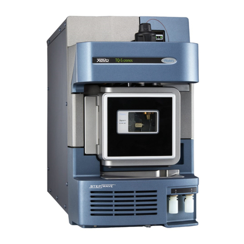
Waters Xevo TQ-S micro Operating manual

Waters Xevo TQ-S micro
Overview and Maintenance Guide
715004599/ Revision B
Copyright © Waters Corporation 2014 – 2016
All rights reserved

ii January 11, 2016, 715004599 Rev. B

January 11, 2016, 715004599 Rev. B iii
General Information
Copyright notice
© 2014 – 2016 WATERS CORPORATION. PRINTED IN THE UNITED STATES OF
AMERICA AND IN IRELAND. ALL RIGHTS RESERVED. THIS DOCUMENT OR
PARTS THEREOF MAY NOT BE REPRODUCED IN ANY FORM WITHOUT THE
WRITTEN PERMISSION OF THE PUBLISHER.
The information in this document is subject to change without notice and should not be
construed as a commitment by Waters Corporation. Waters Corporation assumes no
responsibility for any errors that may appear in this document. This document is believed
to be complete and accurate at the time of publication. In no event shall Waters
Corporation be liable for incidental or consequential damages in connection with, or
arising from, its use. For the most recent revision of this document, consult the Waters
Web site (waters.com).
Trademarks
ACQUITY, ACQUITY UltraPerformance LC, ACQUITY UPLC, Alliance, Connections
INSIGHT, ESCi, MassLynx, “THE SCIENCE OF WHAT’S POSSIBLE”, UPLC, Waters,
Waters Quality Parts, and Xevo are registered trademarks of Waters Corporation, and
iKey, IntelliStart, ionKey, ionKey/MS, IonSABRE, NanoFlow, RADAR, T-Wave, and
ZSpray are trademarks of Waters Corporation.
DART is a registered trademark of JEOL USA Inc.
GELoader is a registered trademark of New Brunswick Scientific, Co., Inc.
LDTD is a trademark of Phytronix Technologies Inc.
PEEK is a trademark of Victrex Corporation.
Phillips and Pozidriv are registered trademarks of Phillips Screw Company, Inc.
snoop and Swagelok are registered trademarks of Swagelok Company.
Spark Holland and Symbiosis are trademarks of Spark-Holland BV.
Viton is a registered trademark of DuPont.
Other registered trademarks or trademarks are the sole property of their owners.

iv January 11, 2016, 715004599 Rev. B
Customer comments
Waters’ Technical Communications organization invites you to report any errors that you
encounter in this document or to suggest ideas for otherwise improving it. Help us better
understand what you expect from our documentation so that we can continuously improve
its accuracy and usability.
We seriously consider every customer comment we receive. You can reach us at
tech_comm@waters.com.
Contacting Waters
Contact Waters®with enhancement requests or technical questions regarding the use,
transportation, removal, or disposal of any Waters product. You can reach us via the
Internet, telephone, or conventional mail.
Safety considerations
Some reagents and samples used with Waters instruments and devices can pose chemical,
biological, or radiological hazards (or any combination thereof). You must know the
potentially hazardous effects of all substances you work with. Always follow Good
Laboratory Practice, and consult your organization’s standard operating procedures.
Waters contact information:
Contacting medium Information
Internet The Waters Web site includes contact information for
Waters locations worldwide. Visit www.waters.com.
Telephone and fax From the USA or Canada, phone 800 252-4752, or
fax 508 872 1990.
For other locations worldwide, phone and fax
numbers appear in the Waters Web site.
Conventional mail Waters Corporation
34 Maple Street
Milford, MA 01757
USA

January 11, 2016, 715004599 Rev. B v
Safety hazard symbol notice
Documentation needs to be consulted in all cases where the symbol is used to find
out the nature of the potential hazard and any actions which have to be taken.
Considerations specific to the Xevo TQ-S micro
Power cord replacement hazard
Solvent leakage hazard
The source exhaust system is designed to be robust and leak-tight. Waters recommends
you perform a hazard analysis, assuming a maximum leak into the laboratory atmosphere
of 10% LC eluate.
Warning: To avoid electric shock, use the SVT-type power cord in the United
States and HAR-type (or better) in Europe. The main power cord must only be
replaced with one of adequate rating. For information regarding what cord to use in
other countries, contact your local Waters distributor.
Warning:
• To confirm the integrity of the source exhaust system, renew the source
O-rings at intervals not exceeding one year.
• To avoid chemical degradation of the source O-rings, which can
withstand exposure only to certain solvents (see page 258), determine
whether any solvents you use that are not listed are chemically
compatible with the composition of the O-rings.

vi January 11, 2016, 715004599 Rev. B
Spilled solvents hazard
Flammable solvents hazard
When using flammable solvents, ensure that a stream of nitrogen continuously flushes the
instrument’s source, and the nitrogen supply pressure remains above 400 kPa (4 bar,
58 psi). You must also install a gas-fail device that interrupts the solvent flowing from the
LC system in the event the supply of nitrogen fails.
Overload hazard
Prohibited: To avoid injury or equipment damage caused by spilled solvent, do
not place reservoir bottles on top of the instrument or on its front ledge.
Warning: To prevent ignition of flammable solvent vapors in the enclosed space
of a mass spectrometer’s ion source, ensure that nitrogen flows continuously
through the source. The nitrogen supply pressure must not fall below 400 kPa
(4 bar, 58 psi) during an analysis requiring the use of flammable solvents. Also a
gas-fail device must be installed, to interrupt the flow of LC solvent should the
nitrogen supply fail.
Warning: To prevent personal injury, ensure equipment placed on top of the Xevo
TQ-S micro does not exceed 15kg.

January 11, 2016, 715004599 Rev. B vii
Glass-breakage hazard
High temperature hazard
Xevo TQ-S micro high temperature hazard:
Warning: To avoid injuries from broken glass, falling objects, or
exposure to toxic or biohazardous substances, never place containers
on top of the instrument or on its front covers.
Warning: To avoid burn injuries, ensure the source heater is turned off and the ion
block is cool before performing maintenance on these components. The source ion
block, located behind the source enclosure assembly, can become hot.
Source enclosure assemblySource enclosure assembly

viii January 11, 2016, 715004599 Rev. B
Hazards associated with removing an instrument from service
When you remove the instrument from use to repair or dispose of it, you must
decontaminate all of its vacuum areas. These are the areas in which you can expect to
encounter the highest levels of contamination:
• Source interior
• Waste tubing
• Exhaust system
• Rotary pump oil (where applicable)
The need to decontaminate other vacuum areas of the instrument depends on the kinds of
samples the instrument analyzed and their levels of concentration. Do not dispose of the
instrument or return it to Waters for repair until the authority responsible for approving its
removal from the premises specifies the extent of decontamination required and the level
of residual contamination permissible. That authority must also prescribe the method of
decontamination to be used and the appropriate protection for personnel undertaking the
decontamination process.
You must handle items such as syringes, fused silica lines, and borosilicate tips used to
carry sample into the source area in accordance with laboratory procedures for
contaminated vessels and sharps. To avoid contamination by carcinogens, toxic
substances, or biohazards, you must wear chemical-resistant gloves when handling or
disposing of used oil.
Bottle placement prohibition
Warning: To avoid personal contamination with biohazards, toxic
materials, or corrosive materials, wear chemical-resistant gloves
during all phases of instrument decontamination.
Warning: To avoid puncture injuries, handle syringes, fused silica
lines, and borosilicate tips with extreme care.
Prohibited: To avoid injury from electric shock or fire, and to prevent damage to
the workstation and ancillary equipment, do not place objects filled with
liquid—such as solvent bottles—on these items, or expose them to dripping or
splashing liquids.

January 11, 2016, 715004599 Rev. B ix
FCC radiation emissions notice
Changes or modifications not expressly approved by the party responsible for compliance,
could void the users authority to operate the equipment. This device complies with Part 15
of the FCC Rules. Operation is subject to the following two conditions: (1) this device
may not cause harmful interference, and (2) this device must accept any interference
received, including interference that may cause undesired operation.
Electrical power safety notice
Do not position the instrument so that it is difficult to operate the disconnecting device.
Equipment misuse notice
If the equipment is used in a manner not specified by the manufacturer, the protection
provided by the equipment may be impaired.
Safety advisories
Consult Appendix A for a comprehensive list of warning advisories and notices.

x January 11, 2016, 715004599 Rev. B
Operating this instrument
When operating this instrument, follow standard quality-control (QC) procedures and the
guidelines presented in this section.
Applicable symbols
Symbol Definition
Manufacturer
Date of manufacture
Part number catalog number
Serial number
Supply ratings
Authorized representative of the European Community
Confirms that a manufactured product complies with all
applicable European Community directives
or
Australia EMC Compliant
Confirms that a manufactured product complies with all
applicable United States and Canadian safety requirements
5()

January 11, 2016, 715004599 Rev. B xi
Consult instructions for use
Electrical and electronic equipment with this symbol may
contain hazardous substances and should not be disposed
of as general waste.
For compliance with the Waste Electrical and Electronic
Equipment Directive (WEEE) 2012/19/EU, contact Waters
Corporation for the correct disposal and recycling
instructions.
Symbol Definition

xii January 11, 2016, 715004599 Rev. B
Audience and purpose
This guide is for operators of varying levels of experience. It gives an overview of the
instrument and explains how to prepare it for operation, switch between modes of
operation, and maintain it.
Intended use of the Xevo TQ-S micro
Waters designed the Xevo TQ-S micro for use as a research tool to accurately,
reproducibly, and robustly quantify target compounds present at the lowest possible levels
in highly complex sample matrices. The Xevo TQ-S micro is not intended for use in
diagnostic applications.
Calibrating
To calibrate LC systems, follow acceptable calibration methods using at least five
standards to generate a standard curve. The concentration range for standards should
include the entire range of QC samples, typical specimens, and atypical specimens.
When calibrating mass spectrometers, consult the instrument’s online Help system for
instructions.
Quality control
Routinely run three QC samples that represent subnormal, normal, and above-normal
levels of a compound. If sample trays are the same or very similar, vary the location of the
QC samples in the trays. Ensure that QC sample results fall within an acceptable range,
and evaluate precision from day to day and run to run. Data collected when QC samples
are out of range might not be valid. Do not report these data until you are certain that the
instrument performs satisfactorily.
When analyzing samples from a complex matrix such as soil, tissue, serum/plasma, whole
blood, and other sources, note that the matrix components can adversely affect LC/MS
results, enhancing or suppressing ionization. To minimize these matrix effects, adopt the
following measures:
• Prior to the instrumental analysis, use appropriate sample pretreatment such as
protein precipitation, liquid/liquid extraction (LLE), or solid phase extraction (SPE)
to remove matrix interferences.
• Whenever possible, verify method accuracy and precision using matrix-matched
calibrators and QC samples.

January 11, 2016, 715004599 Rev. B xiii
• Use one or more internal standard compounds, preferably isotopically labeled
analytes.
EMC considerations
Canada spectrum management emissions notice
This class A digital product apparatus complies with Canadian ICES-001.
Cet appareil numérique de la classe A est conforme à la norme NMB-001.
ISM Classification: ISM Group 1 Class A
This classification has been assigned in accordance with CISPR 11 Industrial Scientific
and Medical, (ISM) instrument requirements. Group 1 products apply to intentionally
generated and/or used conductively coupled radio-frequency energy that is necessary for
the internal functioning of the equipment. Class A products are suitable for use in all
establishments other than residential locations and those directly connected to a low
voltage power supply network supplying a building for domestic purposes.
There may be potential difficulties in ensuring electromagnetic compatibility in other
environments due to conducted as well as radiated disturbances.
Do not use the equipment in close proximity to sources of strong electromagnetic radiation
(for example, unshielded intentional RF sources), as these may interfere with the
equipment’s proper operation.
This equipment complies with the emission and immunity requirements described in the
relevant parts of IEC/EN 61326: Electrical equipment for measurement, control and
laboratory use — EMC requirements.

xiv January 11, 2016, 715004599 Rev. B
EC authorized representative
Waters Corporation
Stamford Avenue
Altrincham Road
Wilmslow
SK9 4AX
United Kingdom
Telephone: +44-161-946-2400
Fax: +44-161-946-2480
Contact: Quality manager

January 11, 2016, 715004599 Rev. B xv
Copyright notice ..................................................................................................................... iii
Trademarks ............................................................................................................................. iii
Customer comments .............................................................................................................. iv
Contacting Waters ................................................................................................................. iv
Safety considerations ............................................................................................................. iv
Safety hazard symbol notice............................................................................................... v
Considerations specific to the Xevo TQ-S micro............................................................... v
FCC radiation emissions notice......................................................................................... ix
Electrical power safety notice............................................................................................ ix
Equipment misuse notice................................................................................................... ix
Safety advisories................................................................................................................ ix
Operating this instrument ...................................................................................................... x
Applicable symbols ............................................................................................................ x
Audience and purpose....................................................................................................... xii
Intended use of the Xevo TQ-S micro.............................................................................. xii
Calibrating ........................................................................................................................ xii
Quality control.................................................................................................................. xii
EMC considerations ............................................................................................................. xiii
Canada spectrum management emissions notice............................................................. xiii
ISM Classification: ISM Group 1 Class A...................................................................... xiii
EC authorized representative ............................................................................................. xiv
1 Specifications and Operating Modes ....................................................................... 23
Uses and compatibility ......................................................................................................... 24
ACQUITY Xevo TQ-S micro UPLC/MS systems........................................................... 26
Software and data system ................................................................................................. 29
Ionization techniques and source probes ........................................................................... 31
Electrospray ionization (ESI) ........................................................................................... 31
Table of Contents

xvi January 11, 2016, 715004599 Rev. B
Combined ESI and APCI (ESCi)...................................................................................... 31
Atmospheric pressure chemical ionization (APCI).......................................................... 31
Dual-mode APPI/APCI source......................................................................................... 31
NanoFlow source.............................................................................................................. 32
Atmospheric solids analysis probe (ASAP) ..................................................................... 33
Atmospheric pressure gas chromatography (APGC) ....................................................... 33
ionKey source................................................................................................................... 33
IntelliStart Fluidics system .................................................................................................. 34
Functionality..................................................................................................................... 34
System operation .............................................................................................................. 35
Ion optics ............................................................................................................................... 36
MS operating modes ............................................................................................................ 36
MS/MS operating modes ..................................................................................................... 38
Product (daughter) ion mode............................................................................................ 39
Precursor (parent) ion mode ............................................................................................. 40
Multiple reaction monitoring mode.................................................................................. 40
Constant neutral loss mode............................................................................................... 42
Sample inlet .......................................................................................................................... 43
Leak sensors ......................................................................................................................... 43
Vacuum system ..................................................................................................................... 43
Rear panel connections ........................................................................................................ 44
2 Preparing for Operation ........................................................................................... 45
Starting the mass spectrometer ........................................................................................... 46
Verifying the instrument’s state of readiness.................................................................... 49
Monitoring the instrument LEDs...................................................................................... 49
Tuning and calibration information.................................................................................. 49
Running the instrument at different flow rates................................................................. 50
Preparing the IntelliStart Fluidics system ......................................................................... 51
Installing the reservoir bottles .......................................................................................... 51
Purging the infusion pump................................................................................................ 53

January 11, 2016, 715004599 Rev. B xvii
Rebooting the instrument .................................................................................................... 53
Leaving the mass spectrometer ready for operation ........................................................ 54
Emergency shutdown of the mass spectrometer............................................................... 54
3 Changing the Mode of Operation ............................................................................ 55
ESI mode ............................................................................................................................... 56
Installing the ESI probe.................................................................................................... 56
Removing the ESI probe................................................................................................... 59
ESCi mode ............................................................................................................................ 60
Optimizing the ESI probe for ESCi operation.................................................................. 60
APCI mode ........................................................................................................................... 60
Installing the IonSABRE II probe .................................................................................... 61
Removing the IonSABRE II probe................................................................................... 64
Combined APPI/APCI source ............................................................................................. 65
APPI operation.................................................................................................................. 65
APCI operation................................................................................................................. 66
Dual-mode operation ........................................................................................................ 67
The combined APPI/APCI source components................................................................ 68
Installing the combined APPI/APCI source ..................................................................... 70
Removing the IonSABRE II probe and APPI/APCI source enclosure ............................ 71
NanoFlow source .................................................................................................................. 72
Installing the NanoFlow source........................................................................................ 73
Fitting a borosilicate glass capillary (nanovial)................................................................ 76
Positioning the borosilicate glass capillary tip ................................................................. 79
ionKey source ....................................................................................................................... 80
Installing the ionKey source............................................................................................. 80
Installing ionKey source software.................................................................................... 85
Installing the camera in the ionKey source....................................................................... 86
Removing the ionKey source............................................................................................ 86

xviii January 11, 2016, 715004599 Rev. B
4 Maintenance Procedures .......................................................................................... 89
Maintenance schedule .......................................................................................................... 91
Spare parts ............................................................................................................................ 93
Troubleshooting with Connections INSIGHT ................................................................... 94
Safety and handling ............................................................................................................. 95
Preparing the instrument for operations on or inside its source ..................................... 97
Removing and refitting the source enclosure .................................................................... 98
Removing the source enclosure from the instrument ....................................................... 98
Fitting the source enclosure to the instrument................................................................ 100
Installing and removing the corona pin ........................................................................... 101
Installing the corona pin in the source............................................................................ 101
Removing the corona pin from the source...................................................................... 103
Operating the source isolation valve ................................................................................ 104
Removing O-rings and seals .............................................................................................. 107
Cleaning the instrument case ............................................................................................ 108
Emptying the exhaust trap bottle ..................................................................................... 108
Gas ballasting the roughing pump .................................................................................... 110
Checking the roughing pump oil level ............................................................................... 112
Adding oil to the roughing pump ....................................................................................... 113
Cleaning the source components ....................................................................................... 114
Cleaning the sampling cone assembly ............................................................................... 115
Removing the sampling cone assembly from the source................................................. 115
Disassembling the sampling cone assembly.................................................................... 117
Cleaning the sample cone and cone gas nozzle.............................................................. 120
Assembling the sampling cone assembly ....................................................................... 122
Fitting the sampling cone assembly to the source .......................................................... 123
Cleaning the ion block assembly ....................................................................................... 125
Removing the ion block assembly from the source assembly........................................ 125

January 11, 2016, 715004599 Rev. B xix
Disassembling the source ion block assembly................................................................ 127
Cleaning the ion block components................................................................................ 132
Assembling the source ion block assembly.................................................................... 133
Fitting the ion block assembly to the source assembly................................................... 135
Cleaning the ion guide assembly ....................................................................................... 135
Removing the pumping block assembly and ion guide assembly from the instrument . 136
Removing the ion guide assembly and differential aperture from the pumping block
assembly................................................................................................................... 137
Removing the differential aperture support and the differential aperture from the ion guide
assembly................................................................................................................... 138
Cleaning the differential aperture ................................................................................... 140
Cleaning the ion guide assembly.................................................................................... 141
Fitting the differential aperture and the differential aperture support onto the ion guide
assembly................................................................................................................... 143
Fitting the ion guide assembly and differential aperture onto the pumping block assembly .
144
Fitting the pumping block assembly and ion guide assembly onto the instrument........ 145
Replacing the ESI probe tip and gasket ........................................................................... 146
Replacing the probe tip and gasket................................................................................. 146
Replacing the ESI probe capillary.................................................................................. 150
Cleaning the IonSABRE II probe tip ............................................................................... 166
Replacing the IonSABRE II probe sample capillary ...................................................... 167
Removing the existing capillary..................................................................................... 167
Installing the new capillary............................................................................................. 169
Cleaning or replacing the corona pin ............................................................................... 172
Replacing the IonSABRE II probe heater ....................................................................... 174
Removing the IonSABRE II probe heater...................................................................... 174
Fitting the new IonSABRE II probe heater .................................................................... 176
Replacing the ion block source heater .............................................................................. 177
Replacing the source assembly seals ................................................................................. 180
Removing the probe adjuster assembly probe and source enclosure seals..................... 181
Fitting the new source enclosure and probe adjuster assembly seals............................. 183

xx January 11, 2016, 715004599 Rev. B
Replacing the air filter ....................................................................................................... 184
Replacing the roughing pump oil ..................................................................................... 187
Replacing the roughing pump’s oil demister element .................................................... 190
APPI/APCI source—changing the UV lamp bulb .......................................................... 195
APPI/APCI source—cleaning the lamp window ............................................................. 196
APPI/APCI source—replacing the APPI lamp drive seals ............................................ 198
Removing the APPI lamp drive assembly seals............................................................. 198
Fitting the new APPI lamp drive assembly O-rings....................................................... 204
Replacing the fluidic lines of the ionKey source .............................................................. 206
Removing a fluidic line .................................................................................................. 207
Installing a fluidic line.................................................................................................... 210
Cleaning the ionKey source and connectors ..................................................................... 211
Replacing the instrument’s fuses ...................................................................................... 214
A Safety Advisories .................................................................................................... 215
Warning symbols ................................................................................................................ 216
Specific warnings............................................................................................................ 217
Notices ................................................................................................................................. 220
Prohibition symbol ............................................................................................................. 220
Warnings that apply to all Waters instruments and devices .......................................... 221
Warnings that address the replacing of fuses .................................................................. 226
Electrical and handling symbols ....................................................................................... 227
Electrical symbols........................................................................................................... 227
Handling symbols........................................................................................................... 228
B External Connections ............................................................................................. 231
External wiring and vacuum connections ........................................................................ 232
Connecting the oil-filled roughing pump ......................................................................... 233
Connecting electric cables to the oil-filled roughing pump............................................ 237
Table of contents
Other Waters Measuring Instrument manuals
