WaterSentinel WSUV Series User manual

Installation, Operation and Maintenance Manual for
Model WSUV Series UltraViolet Modules
Please read complete manual prior to proceeding with the installation of the modules.
Failure to follow instructions and/or operating parameters as specified in the
manual by the manufacturer may lead to the product's failure.
This system requires a GFCI electrical outlet at point of installation.
www.tstwater.com 866-218-8473
42188 Rio Nedo
Temecula, CA 92590

WSUV-4 WSUV-6 WSUV-8
Temperature Range: 40-100°F (4.4-37.8°C)
Pressure Range: 20-125 psi (1.4-8.62 bar)
Flow Rate: 0.5 gpm (1.9 Lpm) 1.0 gpm (3.8 Lpm 2.0 gpm (7.6 Lpm)
UV Bulb Life: 12 Months
Dimensions:
2” x 10” (51 mm x 254 mm) 2” x 13” (51 mm x 330 mm) 2” x 16” (51 mm x 406 mm)
Ballast: 120 Volts 60Hz 8W
Thank you for your purchase of a state of the art
WaterSentinel®water treatment UV Module!
• UV Ballast: One ballast model powers all (WSUV-4, WSUV-6 and WSUV-8)
WaterSentinel brand UV models for use with North American outlets (120V AC, 60Hz).
• UV Lamp: Assembled with high quality components, the UV Lamp is designed to
deliver 12 months of uninterrupted service.
• UV Quartz Tube: Made of high-quality quartz to ensure full UV Lamp exposure.
• UV Body: Designed with Glow End Cap to allow for easy monitoring and
troubleshooting.
• One built-in flow restrictor
• Necessary installation/mounting hardware
The WSUV Water Treatment Modules Feature:
This WaterSentinel brand Ultra Violet module has been designed with high quality and
simplicity in mind. The easy to use quick connect fittings allow for easy connection and
disconnection during maintenance. Hassle-free, disposable design, provide a cost effective
and simple maintenance alternative to costly UV modules in the marketplace today.
Safety First!
Checklist:
❏Do not use with water that is microbiologically unsafe or of unknown quality without
adequate disinfection before and/or after the system.
❏Use GFCI electrical outlet
❏Clean up any water spills and dry hands before handling any electrical components.
❏Do not use extension cords
❏Confirm power source is designed to fit with ballast rating 120V AC, 60 Hz.
❏Protect the UV Module from freezing
❏UV Module is intended for installation on the cold water supply line only.
❏Installation must comply with State and Local plumbing regulations
❏Designed to provide up to 12 Months / 9,000 hours of life
Specifications:
www.tstwater.com 866-218-84732

Module Installation
1. Locate and turn off the cold water supply valve that feeds the water to the filtration system.
2. Open the handle on the filtration system faucet to drain and depressurize the system.
3. Choose the mounting clips to be used for the UV.
a) Single-sided clips: Attach to the top of system bracket
b) Double-sided clips: Attach to the top of RO membrane housing
4. Locate the 1/4” tube where the UV Module will be installed / spliced-in and cut tube
square taking the location of the inlet and outlet connection of the UV Module into
consideration. (Additional ¼” tubing is included in the kit)
NOTE: The UV Module is typically installed on the tube connected to the water filter dispenser faucet.
5. Connect the Inlet tube to the UV Cap (Wire connector end) by pushing the tube firmly into
the elbow fitting.
6. Connect the Outlet tube to the UV Body by pushing the tube firmly into the elbow fitting.
7. Secure the UV module in the filter clips provided.
8. Close the handle to your filtration system faucet and turn on the cold water supply angle
valve to your filtration system.
9. Inspect for leaks and repair as needed (check tube for clean and square cute).
10. Clean up any water that may be left in the installation area.
11. Plug the Ballast connector into the UV Module connector.
12. Ensure there is no water present in the area before attempting to plug the ballast into a
GFCI electrical outlet. Confirm the status of the lamp by checking for blue “Glow” from the
UV Module cap. If lamp does not turn on, check the electrical outlet.
13. Inspect for leaks over the next 24 hours.
Using QuickConnect fittings
www.tstwater.com 866-218-84733
CONNECTION SIZE LOCATION ON UV MODULE
Inlet 1/4” QC UV Cap (Wire connector end)
Outlet 1/4” QC UV Body
To make connection
Push the tube all way to the tube stop. The
collet has stainless steel teeth which hold
the tube firmly in position while the o-ring
provides a leak-proof seal. Pull lightly on
the tube to check that it is secure.
To Disconnect
Push in the collet against the face of the
quick connect fitting. With the collet held in
this position, the tube can be removed.
Before re-connecting, make sure the tube is
free of burrs and sharp edges, trim if needed.

Maintenance
The UV Module should be replaced every 9,000 hours or 12 months.
1. Locate and turn off the cold water supply valve that feeds the water to the filtration system.
2. Unplug the ballast from electrical outlet and disconnect at connector from the UV Module.
3. Open the handle on your filtration system faucet to drain and depressurize the system.
4. Disconnect the inlet and outlet tubes from the UV module and remove the elbow fittings.
(See “Using Quick Connect Fittings” on Page 3 for instructions on how to disconnect the
inlet and outlet tubes.)
5. Remove old UV Module from holding clips.
6. Attach elbow fittings to new UV module by pushing them firmly into the 1/4” openings at
each end of module.
7. Connect the Inlet tube to the UV Cap (Wire connector end) by pushing the tube firmly into
the elbow fitting.
8. Connect the Outlet tube to the UV Body by pushing the tube firmly into the elbow fitting.
9. Secure the UV module in the filter clips.
10. Close the handle on your filtration system faucet and turn on the cold water supply angle
valve to the filtration system.
11. Inspect for leaks and repair as needed.
12. Clean up any water in the installation area.
13. Plug the Ballast connector into the UV Module connector.
14. Ensure there is no water present in the area before attempting to plug the ballast into a
GFCI electrical outlet. Confirm the status of the lamp by checking for blue “Glow” from the
UV Module cap. If lamp does not turn on, check the electrical outlet.
15. Inspect for leaks over the next 24 hours.
www.tstwater.com 866-218-84734

WSUV-4 WSUV-6 WSUV-8
Temperature Range: 40-100°F (4.4-37.8°C)
Pressure Range: 20-125 psi (1.4-8.62 bar)
Maximum Flow Rate: 0.5 gpm (1.9 Lpm) 1.0 gpm (3.8 Lpm 2.0 gpm (7.6 Lpm)
Rated Capacity: 12 Months
Performance Data Sheet
TST Water, LLC
42188 Rio Nedo
Temecula, CA 92590
WSUV-4, WSUV-6, WSUV-8
GENERAL USE CONDITIONS:
System to be used with municipal or well water sources treated and tested on regular basis to
ensure bacteriological safe quality. DO NOT use with water that is microbiologically unsafe or
unknown quality without adequate disinfection before and/or after the system.
RECOMMENDED REPLACEMENT
PARTS AND CHANGE INTERVALS:
NOTE: Depending on incoming feed water conditions replacement time may vary.
DESCRIPTION PART NUMBER CHANGE TIME FRAME
WSUV-4 103017 12 Months or 9,000 Hours
WSUV-6 103028 12 Months or 9,000 Hours
WSUV-8 103029 12 Months or 9,000 Hours
www.tstwater.com 866-218-84735

Limited Warranty
Unless otherwise provided in a warranty for the specific product purchased, Seller hereby
warrants that all goods purchased hereunder shall be free from material defects in material and
workmanship for a period of one (1) year from the date of shipment to Buyer. The foregoing
warranty shall not be valid if the product or component parts have been subjected to abuse,
misuse, accident, alteration, neglect, unauthorized repair or installation. The foregoing warranty
is also contingent upon the proper use of the product and expires immediately upon the
modification or enhancement of the product by anyone without the express written consent of
the Seller.
Upon discovery of any defect in material or workmanship within one year from the date of
shipment, Buyer shall notify Seller within five (5) days of Buyer's discovery of such defect. If such
goods are proven to be materially defective to Seller's, and only Seller's, reasonable satisfaction,
then such defective goods shall be repaired or replaced at Seller's sole option. In the event the
goods cannot be repaired or replaced, Seller shall issue a credit to Buyer for the purchase price
of the defective goods.
Such repair, replacement, or issuance of credit shall constitute a fulfillment of all liabilities with
respect to such goods. The warranty for all goods sold by Seller but manufactured by others
shall be the warranty provided by such manufacturer for such goods. Seller shall take all
commercially reasonable efforts (other than the payment of money) to provide the
manufacturer's warranty to Buyer.
THIS LIMITED WARRANTY IS THE EXCLUSIVE WARRANTY PROVIDED BY SELLER. SELLER
MAKES NO OTHER WARRANTY, EXPRESS OR IMPLIED, AND THERE IS EXPRESSLY
EXCLUDED ALL WARRANTIES OF MERCHANTABILITY AND FITNESS FOR A PARTICULAR
PURPOSE. BUYER'S SOLE REMEDY SHALL BE REPAIR OR REPLACEMENT OF DEFECTIVE
PRODUCTS, OR, IF THE PRODUCT CANNOT BE REPAIRED OR REPLACED, TO RECEIVE
CREDIT FOR THE PURCHASE PRICE OF THE DEFECTIVE PRODUCT. Seller is not liable for
damage to goods, property or persons arising out of the improper installation of such goods;
modification, repair or tampering of such goods by anyone other than Seller; misuse of the
goods; or utilization of the goods under conditions exceeding specifications for such goods.
www.tstwater.com 866-218-84736
This manual suits for next models
3
Table of contents
Popular Water Filtration System manuals by other brands

Clean Water Systems
Clean Water Systems Pro-OX 5700-E Installation & start?up guide
THERMEx
THERMEx PLASMEXFILTER manual
MANN+HUMMEL
MANN+HUMMEL ProVent 400 Series operating instructions

Aozora
Aozora AZ-805 instruction manual
SMC Networks
SMC Networks FGD series operating manual
Maico
Maico ZF ECD Mounting instructions

Waterite
Waterite TriPlex DuPlex FS-BB Series Installation and owner's manual
Pentair
Pentair CLEAN AND CLEAR RP Installation and user guide
HAEGER
HAEGER WJ WHI 001A User instructions
GE
GE Smart Water PNRV18ZBB01 owner's manual
Watts
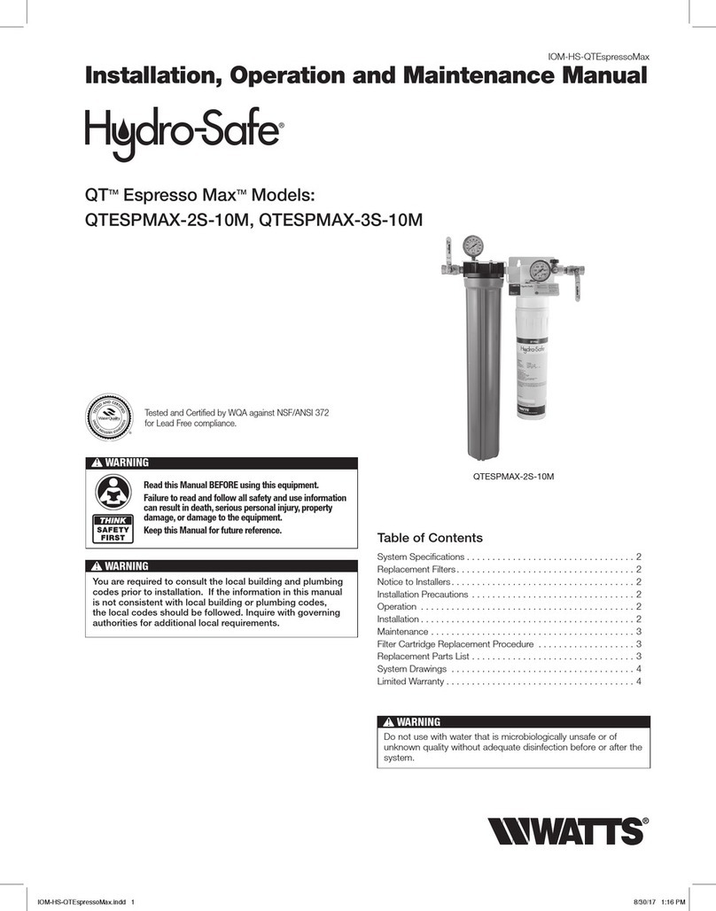
Watts Hydro-Safe QTESPMAX-2S-10M Installation, operation and maintenance manual

Pentair
Pentair EVERPURE MRS-350BL quick start guide
